On-Line Operation
UMSITRPDS3-1
November
2010
6-2
6.1.2 Numeric Display
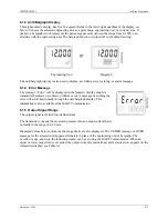
The 5-digit numeric display can be configured to show one of the following.
•
Transmitter current output (4-20 mA or %, selection shown in the unit/bargraph display)
•
Pressure value, in percent, relative to the set range
•
Measured value in a selectable engineering unit (shown on the unit/bargraph display)
Sign for the Measured Value
When the measured value is a negative number, the minus sign is lighted.
Status Arrows
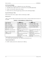
Table 6-1 shows the modes in which the status arrows are active, as well as the meaning of each arrow for
each mode.
TABLE 6-1 Operating Mode and Status Arrows
Operating Mode
1
Status
(
(Display)
Status
'
(Display)
Mode 2 (set zero
2
)
Upper current limit exceeded
Lower current limit exceeded
Mode 3 (set full scale
3
)
Upper current limit exceeded
Lower current limit exceeded
Mode 4 (set damping)
Upper damping value exceeded
Lower damping value exceeded
Mode 5 (set zero blind
2
)
Upper sensor limit exceeded
Lower sensor limit exceeded
Mode 6 (set full scale blind
3
)
Upper sensor limit exceeded
Lower sensor limit exceeded.
Mode 7 (set zero position
correction)
Maximum span exceeded by more
than 5%
-----
Mode 12 (set root switch point)
Square root switch point exceeded
by more than 15%
Dropped 5% below the square root
switch point
Magnetic Pushbutton Operation
(Mode 2, 3, 5, or 6)
Span to be set exceeds the maximum
span
Span to be set is less than the
minimum span
Normal Operation
Output current exceeds the upper
saturation limit or
Input pressure exceeds the upper
sensor limit
Output current is below the lower
saturation limit or
Input pressure is below the lower
sensor limit
1
Operating Mode selected by pressing the M pushbutton.
2
p
min
= minimum operating input pressure;
3
p
max
= maximum operating input pressure
Communication Indicator
)
= HART communication is active when the circle is flashing.
Summary of Contents for 7MF4033 series
Page 48: ...Model 275 Universal Hart Communicator UMSITRPDS3 1 November 2010 2 26 ...
Page 86: ...Installation UMSITRPDS3 1 November 2010 4 34 ...
Page 152: ...Calibration and Maintenance UMSITRPSD3 1 November 2010 7 20 ...
Page 158: ...Circuit Description UMSITRPDS3 1 November 2010 8 6 ...
Page 197: ......
Page 198: ......
Page 200: ...Model Designations and Specifications UMSITRPDS3 1 November 2010 9 42 ...
Page 204: ...Glossary UMSITRPDS3 1 November 2010 10 4 ...
Page 208: ...Appendix A Online Configuration Map UMSITRPDS3 1 11 4 November 2010 ...
Page 216: ...Appendix C Elevation and Suppression Correction UMSITRPDS3 1 13 4 November 2010 ...


