Siemens 6ES7148-6JG00-0BB0 Manual Download Page 36


Communication module CM 8x IO-Link + DI 4x24VDC M12-L (6ES7148-6JG00-0BB0 
Equipment Manual, 09/2020, A5E49284833-AA 

35


Technical specifications 


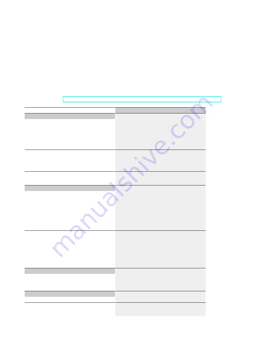
Technical specifications of the CM 8xIO-Link + DI 4x24VDC M12-L communication module 

The following table shows the technical specifications as of 09/2020. You can find a data 

sheet including daily updated technical specifications on the Internet 

(

https://support.industry.siemens.com/cs/de/en/pv/6ES7148-6JG00-0BB0/td?dl=de

)


Article number


6ES7148-6JG00-0BB0


General information


HW functional status 

FS01 

Firmware version 

V1.0.x 


FW update possible 

Yes 

Vendor identification (VendorID) 

002AH 

Device identifier (DeviceID) 

0306H 

Product function


I&M data 

Yes; I&M0 to I&M3 


Prioritized startup 

Yes 

Engineering with


PROFINET from GSD version/GSD revision 

GSDML V2.3.x 

Supply voltage


Load voltage 1L+


Rated value (DC) 

24 V 


permissible range, lower limit (DC) 

20.4 V 


permissible range, upper limit (DC) 

28.8 V 


Reverse polarity protection 

Yes; Against destruction; encoder power supply 

outputs applied with reversed polarity 

Load voltage 2L+


Rated value (DC) 

24 V 


permissible range, lower limit (DC) 

20.4 V 


permissible range, upper limit (DC) 

28.8 V 


Reverse polarity protection 

Yes; against destruction 

Input current


Current consumption (rated value) 

70 mA; without load 

from load voltage 1L+ (unswitched voltage) 

12 A; Maximum value 

from load voltage 2L+, max. 

12 A; Maximum value 

Encoder supply


Number of outputs 

24 V encoder supply


Short-circuit protection 

Yes; per channel, electronic 

Summary of Contents for 6ES7148-6JG00-0BB0

Page 1: ......

Page 2: ...I 4x24VDC M12 L 6ES7148 6JG00 0BB0 Equipment Manual 09 2020 A5E49284833 AA Preface ET 200eco PN M12 L Documentation Guide 1 Product overview 2 Wiring 3 Parameters address space 4 Interrupts diagnostics alarms 5 Technical specifications 6 Dimension drawing A ...

Page 3: ...by personnel qualified for the specific task in accordance with the relevant documentation in particular its warning notices and safety instructions Qualified personnel are those who based on their training and experience are capable of identifying risks and avoiding potential hazards when working with these products systems Proper use of Siemens products Note the following WARNING Siemens product...

Page 4: ...elate in general to the distributed I O devices ET 200eco PN M12 L are described in this system manual The information provided in this equipment manual and in the system manual and the function manuals supports you in commissioning the ET 200eco PN M12 L distributed I O devices Conventions Also observe notes labeled as follows Note A note contains important information On the product described in...

Page 5: ...ww siemens com industrialsecurity Siemens products and solutions undergo continuous development to make them more secure Siemens strongly recommends that product updates are applied as soon as they are available and that the latest product versions are used Use of product versions that are no longer supported and failure to apply the latest updates may increase customers exposure to cyber threats ...

Page 6: ...nctions 14 2 4 Reset communication module to factory settings 16 3 Wiring 17 3 1 Terminal and block diagram 17 3 2 Pin assignment 18 4 Parameters address space 21 4 1 Parameters 21 4 2 Explanation of the parameters 23 4 3 Address space 25 5 Interrupts diagnostics alarms 27 5 1 Status and error displays 27 5 2 Interrupts 31 5 3 Alarms 32 5 3 1 Diagnostics alarms 32 5 3 2 Maintenance events 34 5 3 3...

Page 7: ...TIC ET 200eco PN M12 L distributed I O system The STEP 7 online help supports you in the configuration and programming Device information Product manuals contain a compact description of the module specific information such as properties interfaces wiring diagrams display and operator control elements and technical specifications General information The function manuals contain detailed descriptio...

Page 8: ...My ww en Application examples The application examples support you with various tools and examples for solving your automation tasks Solutions are shown in interplay with multiple components in the system separated from the focus on individual products You will find the application examples on the Internet https support industry siemens com sc ww en sc 2054 TIA Selection Tool With the TIA Selectio...

Page 9: ...e PG PC time converted to UTC time to the module Program download to CPU RUN STOP mode switchover CPU localization by means of LED flashing Reading out of CPU error information Reading the CPU diagnostics buffer Reset to factory settings Firmware update of the CPU and connected modules You can find the SIMATIC Automation Tool on the Internet https support industry siemens com cs ww en view 9816130...

Page 10: ...timally and to plan reserves This helps to prevent problems in commissioning or failures during productive operation even in advance of a planned operation This increases the availability of the production plant and helps improve operational safety The advantages at a glance Network optimization thanks to port specific calculation of the network load Increased production availability thanks to onl...

Page 11: ...I 4x24VDC M12 L 6ES7148 6JG00 0BB0 10 Equipment Manual 09 2020 A5E49284833 AA Product overview 2 2 1 Properties Article number 6ES7148 6JG00 0BB0 View of the module Figure 2 1 View of the CM 8xIO Link DI 4x24VDC M12 L communication module ...

Page 12: ...32 bytes of output data per port Max 265 bytes of input data and 256 bytes of output data per module Automatic backup of device parameters during replacement of the IO Link device only for V1 1 devices Configurable diagnostics can be set for each channel Hardware interrupts Dimensions 45 x 200 mm The module supports the following functions Firmware update Identification and maintenance data I M IO...

Page 13: ...The following component can be ordered as spare part Identification labels The following components can be ordered as accessories Mounting rail Connectors and cables M12 sealing cap See also You can find additional information on the accessories in the ET 200eco PN M12 L distributed I O system http support automation siemens com WW view en 109774008 system manual ...

Page 14: ...ts for connecting PROFINET RN NS RUN network status LED ER MS ERROR module status LED MT IO MAINT IO status LED PWR LED display for load voltage 2L P1 LK LINK port status LED P2 LK LINK port status LED IO L1 to IO L8 LED indicators for channel status IO Link DI0 to DI3 LED indicators for channel status digital input X10 to X13 Sockets for IO Link port Class A and DI X14 to X17 Sockets for IO Link ...

Page 15: ..._LINK_MASTER_8 function block As a result the IO Link ports and the IO Link master are configured with the values stored in the master backup A typical application is the restoration of parameters after replacement of the IO Link master Port Qualifier Information PQI Each port has Port Qualifier Information PQI This PQI provides information on the device status of the port and IO Link The PQI is t...

Page 16: ...ve cleared the Port configuration without S7 PCT PDCT check box in the configuration of all IO Link master submodules in STEP 7 default Procedure You configure the IO Link master with the Port Configuration Tool S7 PCT PDCT V3 5 SP2 or higher Reference For more information on the IO Link system please see the IO Link system http support automation siemens com WW view en 65949252 function manual ...

Page 17: ...ory Reset PROFINET factory reset You can find additional information on the PROFINET factory reset in the ET 200eco PN M12 L distributed I O system http support automation siemens com WW view en 109774008 system manual SIMATIC S7 PCT Factory Reset You trigger the reset to the factory settings in SIMATIC S7 PCT tool A reset is performed completely by IO Link application and affects IO Link related ...

Page 18: ... switched Internal supply voltage 2L Load voltage 2L switched IO Link device class A and 1x switch 2M Ground 2M switched 2x switch 1US 24 V encoder supply Load and 1x switch C Qn IO Link Port n IO Link Device Class B P1 LK P2 LK LED LINK Port 1 Port 2 green X10 to X13 IO Link Port Class A DI RN NS RUN network status LED green X14 to X17 IO Link Port Class B ER MS ERROR module status LED red X80 In...

Page 19: ...nnector The following table shows the pin assignment of the PROFINET connector Table 3 1 Pin assignment of the PROFINET connectors port 1 and 2 Pin Assignment of the core color of the PROFINET cable Assignment Front view of the connect ors Assignment X1 P1 R 1 Yellow TXP 2 White RXP 3 Orange TXN 4 Blue RXN Thread Functional earth FE Assignment X1 P2 R 1 Yellow RXP 2 White TXP 3 Orange RXN 4 Blue T...

Page 20: ... Connector X17 3 Ground 1M non switched 4 IO Link port 1 Connector X10 IO Link port 2 Connector X11 IO Link port 3 Connector X12 IO Link port 4 Connector X13 IO Link port 5 Connector X14 IO Link port 6 Connector X15 IO Link port 7 Connector X16 IO Link port 8 Connector X17 5 Not used Ground 2M switched Note Port Class B The pin assignment of the IO Link interface of the sockets X14 to X 17 corresp...

Page 21: ...of the connector X80 connector POWER input 1 Brown Supply voltage 1L Non switched 2 White Ground 2M switched 3 Blue Ground 1M non switched 4 Black Load voltage 2L switched Pin assignment of the socket for loop through of the supply voltage M12 L coded The table below shows the pin assignment of the M12 L coded socket for loop through of the supply voltage Table 3 4 Pin assignment of the supply vol...

Page 22: ... Default Scope with configu ration software e g STEP 7 TIA Portal Diagnostics Diagnostics Missing 2L Disable Enable Disable Channel Diagnostics undervoltage 1L Disable Enable Disable Channel Diagnostics Port Disable Enable Disable Channel Hardware interrupt device notification Disable Enable Disable Channel Port configuration Port configuration without S7 PCT Disable Enable Disable Channel Operati...

Page 23: ... with configu ration software e g STEP 7 TIA Portal Inspection Level Data Stor age Same type V1 0 without Back up Restore Type compatible V1 1 without Backup Restore Type compatible V1 1 with Back up Restore Type compatible V1 1 with Re store Type compatible V1 1 with Back up Restore Channel Port cycle time As short as possible Channel Only effective if you use the IO Link manual port mode ...

Page 24: ... interrupt device notification Enable of the hardware interrupt for the selected IO Link port The possible hardware interrupts are dependent on the IO Link device used Additional information on the hardware interrupts can be found in the description of the IO Link device used Note Configuration as digital input or digital output Note that you cannot enable any port parameters or diagnostics alarms...

Page 25: ...diately ready for operation IO Link manual The connected IO Link device is not started automatically You must store the Vendor ID and Device ID of the connected IO Link device in STEP 7 Inspection Level Data Storage You can select the inspection level for data storage Identical type V1 0 without Backup Restore Type compatible V1 1 without Backup Restore Type compatible V1 1 with Backup Restore Typ...

Page 26: ...h IO Link port are defined by configuring a corresponding submodule as a digital input by configuring a digital input submodule as a digital output by configuring a digital output submodule as IO Link device by configuring an IO Link submodule Port disabled in STEP 7 V5 5 and higher and with GSD By deleting the submodule in STEP 7 TIA Portal By deactivating the port enable Die IO Link ports are pr...

Page 27: ...s detected 1 Device parameter update detected Bit3 SubstDev 0 No backup device detected identical serial number 1 Backup device detected different serial number Bit4 PortActive 0 Port disabled 1 Port enabled Bit5 DevCom 0 IO Link device is not available 1 IO Link device is in the Preoperate or Operate state Bit6 DevErr 0 No error 1 An error or warning has occurred Bit7 PQ 0 The data of the IO Link...

Page 28: ...ys The following figure shows the LED display of the CM 8xIO Link DI 4x24VDC M12 L communication module RN NS RUN network status ER MS ERROR module status MT IO MAINT IO status PWR POWER LED P1 LK PROFINET port status P2 LK PROFINET port status LED displays IO L1 to IO L8 for channel status channel fault green red LED displays DI0 to DI3 for channel status green Figure 5 1 LED displays ...

Page 29: ...ee LEDs light up simul taneously for approximately 2 s while Reset to factory settings is running Flashes off Off Module is disabled Activate the ET 200eco PN with the configuration soft ware or via the user pro gram Module is not configured Configure the ET 200eco PN via the configuration soft ware Module starts up Parameters are assigned to module Loading firmware when the firmware update is per...

Page 30: ...is missing or too low On green Load voltage 2L present LEDs P1 LK and P2 LK The following table describes the behavior of LEDs that indicate the connection status with a PROFINET IO controller or a PROFINET switch Table 5 3 Status displays of the LEDs P1 LK and P2 LK LEDs Meaning Remedy P1 LK P2 LK off There is no Ethernet connection between the communications interface of your IO device and a com...

Page 31: ... Off Process value 0 On green Process value 1 Channel status channel error LEDs IO Link The LEDs of IO Link port class A and port class B have the same behavior LEDs Meaning Channel status error off Input or output value is 0 or port is disabled On red IO Link communication established active device or channel fault Flashes At startup or permanently if no functional IO Link device was found On gre...

Page 32: ...standard of the extended channel diagnostics USI 0x8002 The CPU interrupts user program execution and processes the diagnostics interrupt OB OB 82 You can determine the error events channel diagnostics with the RALRM instruction Hardware interrupts All IO Link events of the type Notification generated by the IO Link device are mapped to the hardware interrupts of the assigned submodule The coding ...

Page 33: ...FINET channel diagnostics CET ECET from the IO Link events of an IO Link device according to the following mapping regulations In the IO Link Device Diagnostics Page 1 CET 0x9500H the IO Link event codes in the range 0x0000 0x7FFFH are displayed directly ECETH IO Link Event CodeH In the IO Link Device Diagnostics Page 2 CET 0x9501H the IO Link event codes in the range 0x8000 0xFFFFH are displayed ...

Page 34: ...up Check parameter assignment 0x1802H 6146D Wrong device Ven dorID Check device 0x1803H 6147D Wrong device De viceID Check device 0x1804H 6148D Short circuit to C Q Check port connection 0x1805H 6149D IO Link PHY over temperature 0x1806H 6150D Short circuit to L Check port connection 0x1808H 6152D Event overflow on the device 0x1809H 6153D Backup failed Memory outside the range 2k 0x180AH 6154D Ba...

Page 35: ... network component must be checked or replaced Example of displaying the IO Link event codes An IO Link device generates EventCode 0x8CA0H type Warning The channel diagnostics results from the event code PROFINET channel diagnostics type Maintenance CET 0x9501H ECET 0x0CA0H Maintenance IO Link Device Diagnostics Page 2 Ambient light interference generated from the IO Link event code 0x8CA0H 5 3 3 ...

Page 36: ...er DeviceID 0306H Product function I M data Yes I M0 to I M3 Prioritized startup Yes Engineering with PROFINET from GSD version GSD revision GSDML V2 3 x Supply voltage Load voltage 1L Rated value DC 24 V permissible range lower limit DC 20 4 V permissible range upper limit DC 28 8 V Reverse polarity protection Yes Against destruction encoder power supply outputs applied with reversed polarity Loa...

Page 37: ... 61131 type 3 Yes Number of simultaneously controllable inputs all mounting positions up to 60 C max 4 Input voltage Type of input voltage DC Rated value DC 24 V for signal 0 3 to 5V for signal 1 11 to 30V Input current for signal 1 typ 2 5 mA Input delay for rated value of input voltage for standard inputs at 0 to 1 max typically 3 ms at 1 to 0 max typically 3 ms Cable length unshielded max 30 m ...

Page 38: ... of IO Link devices Port type A Yes via 3 core cable Port type B Yes additional device supply max 2 A per port max 6 A per module Interfaces Number of PROFINET interfaces 1 1 Interface Interface type PROFINET with 100 Mbit s full duplex 100BASE TX Interface types Number of ports 2 integrated switch Yes M12 port Yes 2x M12 4 pin D coded Protocols PROFINET IO Device Yes Open IE communication Yes Int...

Page 39: ...hort circuit encoder supply Yes Per channel Diagnostics indication LED RUN LED Yes green LED ERROR LED Yes red LED MAINT LED Yes Yellow LED Channel status display Yes green LED for channel diagnostics Yes red LED For load voltage monitoring Yes green LED Connection display LINK TX RX Yes green LED only link Potential separation between the load voltages Yes between Ethernet and electronics Yes Pot...

Page 40: ...additional restrictions see manual for details Connection method Design of electrical connection for the inputs and outputs M12 5 pin A coded Design of electrical connection for supply volt age M12 4 pin L coded Dimensions Width 45 mm Height 200 mm Depth 48 mm Weights Weight approx 780 g Power reduction derating to total current of outputs per module The following derating curves show the load cap...

Page 41: ... M12 L 6ES7148 6JG00 0BB0 40 Equipment Manual 09 2020 A5E49284833 AA Dimension drawing A The following figure shows the dimension drawing of the CM 8xIO Link DI 4x24VDC M12 L communication module in front and side view Figure A 1 Dimension drawing ...

Reviews: