background image

Infrastructure and Mobility, Traffic Solutions

Sopers Lane, Poole, Dorset

BH17 7ER

Version

7

Page 12 of 76

Status

ISSUED

Last Editor

Ore Oluwatudimu

TS008468

Date

31/01/2017

Document
Name

UPS Solution General Handbook

Doc. No.

667/HB/47750/000

Copyright

 Siemens plc 2017  All Rights Reserved

3  Modular Overview

This section details the five key building blocks of the UPS Solution; the stool, cabinet
outer case and three equipment housing modules.

3.1  UPS Cabinet Modules

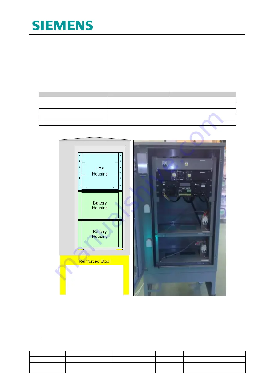
Table 3-1 and Figure 3-1 show the modules involved in making up the UPS cabinet.

UPS Solution Modules

Quantity

Refer to

Reinforced Stool

1

Section 3.3.1

Vented Cabinet Outer Case

1

Section 3.3.2

Battery Housing

2 (maximum)

2

Section 3.3.3

UPS Housing

1

Section 3.3.4

DC Housing

0

N/A

Table 3-1: UPS Cabinet Module Quantities

Figure 3-1: UPS Cabinet Modules

2

 The UPS Cabinet can be fitted with just one Battery Housing module in cases where

reduced battery support is required.

Summary of Contents for 667/HB/47750/000

Page 1: ...hecked and Released Company Dept Siemens Traffic Solutions Engineering Siemens Traffic Solutions Engineering Name Ore Oluwatudimu David Martin Function Product Development Engineer Hardware Engineering Manager Signature Date COPYRIGHT STATEMENT The information contained herein is the property of Siemens plc and is supplied without liability for errors or omissions No part may be reproduced or used...

Page 2: ...ipment 3 The equipment must be correctly connected to the specified incoming power supply 4 Mains voltages may be present within traffic system Before any maintenance work within the system is carried out any mains supply to it must be isolated or switched off 5 Mains voltages may still be present within traffic equipment even when the site mains supply has been isolated or switched off The UPS So...

Page 3: ...t sparks or open flames Protect battery containers from physical damage to avoid leaks or spills Place cardboard or other insulating material between layers of stacked batteries to avoid damage and short circuits Do not allow conductive material to touch the battery terminals A dangerous short circuit may occur and cause battery failure fire arcing flash burns etc Keep away from combustible materi...

Page 4: ...on and commissioning are described in this handbook In addition there are a series of documents which have more specific detail but are supplied by the OEM Original Equipment Manufacturer These documents are listed in section 1 2 below Spares and Maintenance The UPS system elements are designed for return to base repair with the exception of battery replacement Modifications There are no approved ...

Page 5: ...using Module 14 3 3 4 UPS Housing Module 15 3 3 5 DC Housing Module 16 4 Hardware Overview 17 4 1 Alpha FXM UPS unit 17 4 2 Universal Automatic Transfer Switch 18 4 3 Lead Crystal Batteries 19 5 Sizing the UPS Solution 20 5 1 Key Considerations 20 5 2 Sizing Example 21 5 2 1 Which UPS Unit Should be Installed 21 5 2 2 How Many Battery Packs are Required 21 6 Internal Cabling Scheme 23 6 1 UPS Cabi...

Page 6: ...YPASS 43 11 4 Powering and Commissioning the Controller 43 11 5 Starting Up the UPS Solution 43 11 6 Testing the UPS Battery Support Function 44 12 UPS System Operation 45 12 1 Operating Modes 45 12 2 Active Fault Monitoring 45 12 2 1 Fault Alarm Relay Contacts 45 12 2 2 Fault Monitoring using Siemens RMS and UTMC Systems 47 12 3 Communicating with the UPS Solution 48 12 3 1 Three Button Interface...

Page 7: ...re 5 1 Battery Hold up times at 20 C and 0 C 20 Figure 5 2 Sizing Example Battery Pack Selection 22 Figure 6 1 UPS Cabinet Internal Wiring Diagram 23 Figure 6 2 Battery Expansion Cabinet Internal Wiring Diagram 24 Figure 7 1 Mains Power Supply Chain 25 Figure 9 1 Reinforced Stool and CET plate 29 Figure 9 2 Stool Installation Diagram 30 Figure 9 3 Reinforced Stool LEFT HAND SIDE VIEW 31 Figure 9 4...

Page 8: ...rnet Cable Specification 26 Table 7 3 Battery Expansion Cable Specification 26 Table 9 1 Installation Steps for the UPS and Battery Expansion Cabinets 28 Table 9 2 RJ45 Interface Cable Connection 37 Table 12 1 Key UPS Solution Operating Modes 45 Table 12 2 Default Fault Contact Settings 46 Table 12 3 RMS Bit Labelling and Description 47 Table 12 4 RS232 Interface Connection Information 48 Table 12...

Page 9: ... 667 HB 47764 000 Lead Crystal Battery User Manual Betta Batteries 667 US 47764 000 Lead Crystal Battery Material Safety Data Sheet Betta Batteries 667 HE 45950 000 ST950 ELV Installation Commissioning and Maintenance Handbook Dave Martin 667 HE 46950 000 ST950 LV Installation Commissioning and Maintenance Handbook Dave Martin 667 HB 45040 000 Isolators and Feeder Pillars General Handbook Peter Li...

Page 10: ...Siemens traffic controller cabinet outer case to reduce its visual impact When installed the controller and UPS solution cabinets appear identical Two cabinet variants are available as described below UPS Cabinet Houses the UPS system equipment and up to two 48V 55Ah battery banks Battery Expansion Cabinet Houses up to three 48V 55Ah battery banks only The Battery Expansion cabinet can be installe...

Page 11: ...nnect Feeder Pillar 2 5 Electrical Information Parameter Value Input Voltage 230Vac 150Vac 328Vac without switching to battery support Frequency 50Hz 60Hz Auto detect 5 Current at max battery charging current FXM1100 8A at 230Vac FXM2000 15A at 230Vac Mains Input Circuit Breaker Rating 20A at 230Vac Output Voltage 230Vac Frequency 50Hz 60Hz Auto detect 5 Maximum Power 1 FXM1100 1100 W VA FXM2000 2...

Page 12: ...olution the stool cabinet outer case and three equipment housing modules 3 1 UPS Cabinet Modules Table 3 1 and Figure 3 1 show the modules involved in making up the UPS cabinet UPS Solution Modules Quantity Refer to Reinforced Stool 1 Section 3 3 1 Vented Cabinet Outer Case 1 Section 3 3 2 Battery Housing 2 maximum 2 Section 3 3 3 UPS Housing 1 Section 3 3 4 DC Housing 0 N A Table 3 1 UPS Cabinet ...

Page 13: ...ow the modules involved in making up the Battery Expansion Cabinet UPS Solution Modules Quantity Refer to Reinforced Stool 1 Section 3 3 1 Vented Cabinet Outer Case 1 Section 3 3 2 Battery Housing 3 maximum 3 Section 3 3 3 UPS Housing 0 N A DC Housing 1 Section 3 3 5 Table 3 2 Battery Expansion Cabinet Module Quantities Figure 3 2 Battery Expansion Cabinet Modules Cabinet removed 3 The Battery Exp...

Page 14: ...xpansion Cabinet Plastic ventilation devices have been added to the ST950 outer case to provide the additional airflow required by UPS system equipment The vents are fitted behind the cabinet s front door and are invisible when the door is closed 3 3 3 Battery Housing Module UPS Cabinet and Battery Expansion Cabinet The Battery Housing module is the main building block of the internal mounting fra...

Page 15: ...at the end of installation 3 3 4 UPS Housing Module UPS Cabinet ONLY The UPS Housing contains the key system hardware and is the main control and connectivity hub for the entire UPS solution It contains the UPS unit and UATS as described in sections 4 1 and 4 2 as well as a UPS Connection Panel that provides termination for internal and external cabling related to the entire UPS Solution including...

Page 16: ...ghts Reserved 3 3 5 DC Housing Module Battery Expansion Cabinet ONLY The DC Housing provides a Connection Panel similar to that found within the UPS Housing This DC Connection Panel allows for the termination of internal and external cabling related to the Battery Expansion Cabinet only A 63A double pole MCB can be used to isolate the Battery Expansion Cabinet from the rest of the UPS Solution Fig...

Page 17: ... depending on the power requirements of the traffic intersection to be supported FXM1100 Intersections up to 1kW FXM2000 Intersections up to 2kW Key information for each type of unit is listed here For more detailed information please see APPENDIX C Hardware Datasheets or consult the FXM Series UPS Operating Manual 667 HB 47760 000 Parameter FXM1100 FXM2000 Nominal Voltage 230VAC Nominal Frequency...

Page 18: ...been designed to work alongside the Alpha FXM UPS series and includes an automatic transfer facility that constantly monitors the output of the UPS unit and will switch the system to bypass if a fault is detected Figure 4 2 Universal Automatic Transfer Switch Key information on the UATS is listed below For further information on the unit please see APPENDIX C Hardware Datasheets or consult the UAT...

Page 19: ...hese batteries creating a 48V 55Ah pack Lead Crystal batteries have a greatly extended operating temperature range and a longer life expectancy when compared to their Lead Acid equivalents For more detailed information please see APPENDIX C Hardware Datasheets or consult the Lead Crystal Battery User Manual 667 HB 47764 000 Figure 4 3 6CNFT 55 Lead Crystal Battery with Key Electrical Information W...

Page 20: ...o Alpha FXM UPS units is to be installed The required battery support hold up time determines the number of battery packs that will need to be installed within the UPS Solution Extended hold up periods will require the installation of a Battery Expansion Cabinet alongside the UPS Cabinet Where cost or space is critical a compromise between the junction power requirements and required hold up time ...

Page 21: ...tion 12 5 for more information on temperature de rating 5 2 Sizing Example The following subsections give an example of sizing a UPS solution for a traffic intersection in the UK with the following requirements Required Junction Power 900W Desired Hold up Time 3 5 hours WARNING For the majority of UK installations it is reasonable to assume a worst case cabinet temperature range of 0 C to 65 C The...

Page 22: ...dimu TS008468 Date 31 01 2017 Document Name UPS Solution General Handbook Doc No 667 HB 47750 000 Copyright Siemens plc 2017 All Rights Reserved Figure 5 2 Sizing Example Battery Pack Selection NOTE Any solution requiring 3 or more battery packs to achieve its desired hold up time will require the installation of a Battery Expansion Cabinet ...

Page 23: ...attery Expansion cabinets 6 1 UPS Cabinet Internal Wiring BATTERY HOUSING 1 BATTERY HOUSING 2 MCB C1 C6 Faults Alarms 54VDC BUS Battery Mains IN Mains OUT MCB MCB Alpha FXM Series UPS Unit Mains I P CB Battery CB UATS UPS ON OFF UPS BYPASS Mains O P Fault Contacts Mains Supply Controller Supply UPS Connection Panel DIN Rail Terminal Block Switch or Circuit Breaker UPS HOUSING Controller I O Card B...

Page 24: ...r connectivity not shown in Figure 6 1 some of which must be fitted for proper system operation See section 8 for details 6 2 Battery Expansion Cabinet Internal Wiring Figure 6 2 Battery Expansion Cabinet Internal Wiring Diagram As stated in section 3 3 5 the DC Housing comes prewired with all interconnecting wiring looms and the DC Connection Panel provides a termination point for all of these as...

Page 25: ...dictated in the following document 667 HB 45040 000 Isolators and Feeder Pillars General Handbook The UPS cabinet can be installed in any location between the feeder pillar and controller cabinet as long as the total cable length does not exceed the values specified in the above document WARNING The same cable is to be used throughout the mains power supply chain from feeder pillar to controller 7...

Page 26: ...le 998 4 70468 006 Armoured 1 1 13mm 12core PVC cable 998 4 70468 008 Armoured 1 1 13mm 16core PVC cable 998 4 70468 050 Armoured 1 1 13mm 20core PVC cable Table 7 1 Alarm Contact Cable Specification 7 4 Ethernet Cable When the FXM Series UPS unit s LAN interface feature is to be used CAT5e cable is to be ducted into the controller cabinet and connected to an IP enabled Ethernet connection Use the...

Page 27: ...roper installation of the battery temperature sensor see section 9 12 See section 12 5 2 for more information on temperature compensated battery charging 8 2 RS232 Interface Alpha FXM UPS units are fitted with a female 9 way D type connecter for RS232 connectivity to a computer or laptop Status information and configuration settings are made available via this interface and can be used to interrog...

Page 28: ...fer to 1 Prepare and install the Reinforced Stool Section 9 2 2 Pull and gland ducted cables Section 9 3 3 Fit the Vented Cabinet Outer Case and seal the base Section 9 4 4 Fit and connect the Battery Housing module s Section 9 5 5 Mount and connect the UPS housing module N A Section 9 6 6 N A Mount and connect the DC Housing module Section 9 7 7 Terminate External cables into the UPS Connection p...

Page 29: ... Civils Contractor as to the correct orientation of all cabinet stools ensuring all cabinets on site will face the right way The reinforced stool is based on a normal controller cabinet stool and the installation process is much the same WARNING Although similar the normal ST800 ST900 or ST950 cabinet stool must not be used when installing the UPS Solution as it is not capable of supporting the to...

Page 30: ... Pull and gland ducted cables Section 9 3 NOTE It is recommended that the Ethernet cable if fitted is pulled through all conduits prior to attaching the RJ45 termination jack This ensures the termination is not compromised in any way during the pulling procedure See section 9 10 for termination details NOTE Sharp bends in all cables are to be avoided A minimum bend radius of 4x the cable diameter ...

Page 31: ...ery Expansion Cable terminate the Green Yellow core to the main earth stud on the CET plate 9 4 Fitting the Vented Cabinet Outer Case and Sealing the Base Step No UPS Cabinet Battery Expansion Cabinet Refer to 3 Fit the Vented Cabinet Outer Case and seal the base Section 9 4 The Vented Cabinet Outer Case is simply a modified ST900 style controller cabinet and is fitted to the stool in exactly the ...

Page 32: ...e fitted within the Battery Housing module during installation Figure 9 4 Battery Housing Modules stacked on the Reinforced Stool Cabinet removed NOTE Secure external cables from the CET plate to the cable management holes in the left hand side of the Battery Housing modules as each module is installed Fitting the first Battery Housing Module 1 Pass the first battery housing through the front door...

Page 33: ... the cabinet outer case and place on top of the previously installed battery housing 2 Using the back and side stops slide the Battery Housing into place aligning the countersunk holes on the bottom surface with the threaded holes in the top of the Battery Housing module below Secure using the fixings provided Figure 9 5 Battery Housing module mount 3 Pass the loose earth wire from the right side ...

Page 34: ...and remove the FXM UPS unit This can then be replaced once the housing module is securely installed Figure 9 7 UPS Housing mounted on Battery Housing within Cabinet 1 Pass the UPS housing module through the front door aperture of the cabinet outer case and place on top of the previously installed Battery Housing module 2 Using the side stops slide the UPS Housing module into place aligning the hol...

Page 35: ...termination point for all batteries fitted within a Battery Expansion Cabinet 1 Pass the DC Housing module through the front door aperture of the cabinet outer case and place on top of the previously installed Battery Housing module 2 Using the side stops slide the DC Housing module into place aligning the holes in the bottom flange with the threaded holes in the top of the Battery Housing module ...

Page 36: ...nsion Cabinet Refer to 7 Terminate External cables into the UPS Connection panel N A Section 9 8 WARNING Ensure all power sources are switched off and safely isolated before installation commences All switches and MCBs should be in the OFF or BYPASS position 1 Remove the blanking plate from the top of the UPS housing revealing the UPS Connection Panel 2 The DIN rail mounted terminal blocks on the ...

Page 37: ...clearly labelled Terminate the Battery cable from the UPS cabinet to the TBs marked UPS DC 3 Replace the blanking plate See section 7 for further details on external cable specification details 9 10 Terminating and Connecting the Ethernet Cable Step No UPS Cabinet Battery Expansion Cabinet Refer to 9 Terminate and connect the Ethernet Cable N A Section 9 10 If the FXM UPS unit s LAN Interface feat...

Page 38: ... All switches and MCBs should be in the OFF or BYPASS position Each Battery Housing module takes four 12V LC batteries forming a 48V battery pack These will be referred to as Battery 1 2 3 and 4 from left to right respectively Repeat the following steps for each Battery Housing module within UPS cabinet AND Battery Expansion cabinet 1 Lower the battery retention bar of the Battery Housing module S...

Page 39: ...sion Cabinet Refer to 11 Connect the Batt Temp sensor N A Section 9 12 This sensor allows the FXM UPS unit to temperature compensate its battery charging characteristics and is a vital part of the system installation The sensor is to be fitted as follows to the battery pack housed directly below the UPS unit Figure 9 11 Battery Temperature Sensor 1 Ensure the temperature sensor connector is secure...

Page 40: ...ch on off separate system elements These switches are used during commissioning start up and maintenance of the UPS Solution and are referred to throughout the rest of this handbook by the names listed here 10 1 Housing Module MCBs Mains Input MCB UPS Connection Panel UPS Housing UPS cabinet Battery Expansion MCB DC Connection Panel DC Housing Battery Expansion cabinet Battery Housing Isolation MC...

Page 41: ... Oluwatudimu TS008468 Date 31 01 2017 Document Name UPS Solution General Handbook Doc No 667 HB 47750 000 Copyright Siemens plc 2017 All Rights Reserved 10 3 FXM UPS Unit The UPS Unit is mounted within the UPS Housing module at the top of the UPS Cabinet Battery Breaker Input Circuit Breaker Figure 10 2 Alpha FXM UPS Circuit Breakers ...

Page 42: ...the UPS solution must be fitted with a 300mA RCD See section 7 2 for more details 11 1 Electrical Safety Testing Upon completion of UPS Solution installation the following Electrical Safety Tests are to be carried out before the solution is powered or switched on Tests required are set out in the TS Traffic Installation Testing Document 667 HE 20664 000 2 1 Test Gear Requirement 2 2 Core to Core T...

Page 43: ...tion Panel and the Manual Bypass Switch SW1 on the UATS are in the ON and BYPASS position respectively no matter the state of other isolation switches within the solution 11 4 Powering and Commissioning the Controller 1 Ensure the UPS Solution is in BYPASS as per section 11 3 2 Commission the traffic intersection controller in accordance with its related Installation Commissioning and Maintenance ...

Page 44: ...0 N The UPS Solution is now switched on and supporting the traffic Intersection Mains power from the site supply feeder pillar is now fed through the UPS unit before being passed on to the controller 11 6 Testing the UPS Battery Support Function NOTE Enter all results into APPENDIX D UPS Commissioning Certificate 1 Switch the Mains Input MCB on the UPS Housing to OFF 2 Ensure the UPS unit now disp...

Page 45: ...DOWN Mains power from the site supply feeder pillar is unavailable and the batteries have been discharged to the UPS unit s over discharge threshold The UPS Solution switches off Power is no longer supplied to the traffic controller load When mains power is restored at the site supply feeder pillar the UPS solution will automatically switch to RETRAN mode Table 12 1 Key UPS Solution Operating Mode...

Page 46: ...2 47Vdc 40 SOC C4 Timer Dry Contact The UPS Solution has been running on battery backup for a user defined length of time 5 minutes C5 Alarm Dry Contact General Fault on UPS Unit5 N A C6 DO NOT USE See warning below UPS On 48Vdc at 500mA from battery packs The UPS is providing a mains output independent of the power source N A Table 12 2 Default Fault Contact Settings WARNING C6 is factory configu...

Page 47: ...load Avoids nuisance reports when short mains breaks occur UPS ALRM C5 UPS Alarm Urgent There is a fault with the UPS Site visit or remote investigation required Table 12 3 RMS Bit Labelling and Description Example Scenario The LOWB1 C2 contact can be used in two ways The first is as an indication to the controller that the UPS has been running on battery power for some time allowing special condi...

Page 48: ...abled unless the UPS unit has a fault these menus display and fault or alarm flags that are currently active Event Status Menu Allows the user to scroll through the last 25 items listed in the UPS unit s 100 event log For details on all the options available within these menus please refer to the Alpha FXM UPS Operating Manual 667 HB 47760 000 Access to many more system settings can only be achiev...

Page 49: ...erface does not auto refresh and Factory configured unit specification information The Maintenance submenu allows the user to adjust a limited number of UPS settings including changing the connection password and switching systems timers on or off NOTE The connection password applies to all UPS communication interfaces described in section 12 3 Special command prompts can be entered directly into ...

Page 50: ... type the Alpha FXM UPS unit s IP address into a web browser Individual unit s IP addresses can be configured to match networking required The default IP address and password for all UPS units are shown in Table 12 5 Connection Parameters Default Settings IP Address 192 168 0 90 Password 1111 Table 12 5 LAN Interface Connection Information NOTE The connection password applies to all UPS communicat...

Page 51: ... LAN Interface Screenshot Relay Contact Configuration NOTE A similar though slightly restricted GUI can be used with the UPS Solution via the use of the Alpha UPS Monitor software package available for free download from the Alpha Technologies website 7 In depth information on the use of the Alpha UPS Monitor Software and the LAN interface GUI is available within the Alpha FXM UPS Operating Manual...

Page 52: ...e Absorption Used to complete the final stage of battery recharge The charger is now in constant voltage mode and holds the battery voltage at 54Vdc The battery pack is allowed to draw current based on its capacity and chemistry The current drawn continues to decreases as the battery charges Float Used to maintain fully charged batteries As the battery pack nears full charge the current drawn drop...

Page 53: ...0 UPS units offer a maximum power output of 1100VA and 2000VA respectively See section 4 1 In high ambient temperatures the maximum power available decreases as the FXM UPS units reach the limits of their operating range The FXM1100 UPS unit is de rated by 1 25 for every degree above 55 C The FXM2000 UPS unit is de rated by 1 0 for every degree above 50 C Table 12 6 below gives specific figures sh...

Page 54: ...s the available capacity of each battery pack is reduced as battery chemistry becomes increasingly inert This becomes very apparent and extremely low ambient temperatures APPENDIX A Estimated Hold Up Times shows battery hold up runtime charts such as in section 5 adjusted for ambient cabinet temperatures of 20 C 0 C and 25 C 12 6 Generators 12 6 1 The Generator Connect Feeder Pillar As stated in s...

Page 55: ...on 11 2 for more details of the installation TT Earth Electrode test WARNING If there is ANY DOUBT WHATSOEVER about the TT earth provided by the installation e g the TT earth electrode test results are not available then additional reference earthing may be required as described below Additional reference earthing is not required if all three of the following statements are true for the site The c...

Page 56: ...h to OFF 6 Start the Generator and allow at least 10 seconds for its output to settle 7 Switch the changeover switch to GEN 8 Feed the connecting cable through the cable entry slot in the pillar door then close and lock the Generator Connect Feeder Pillar NOTE The UPS solution should now be in LINE mode using the generator power in the place of the mains supply See section 12 1 for more informatio...

Page 57: ...odic inspection Note any faults or alarms flagged by the Alpha FXM UPS unit Clear faults and alarms wherever possible in accordance with UPS Operating Manual 667 HB 47760 000 Report ALL faults and alarms to Line Manager Switch off the mains supply to the UPS by switching CB1 on the UATS to OFF see section 10 2 at the beginning of normal junction periodic inspection Observe the battery voltage via ...

Page 58: ...are set back to the ON Position 13 2 Maintenance Bypass Switching The Maintenance Bypass feature allows maintenance personnel to connect the controller load directly to the mains supply from the site feeder pillar via the Alpha UATS bypassing the FXM UPS unit and its connected battery packs See section 10 for isolation switch information Flip SW1 on the UATS from UPS to BYPASS to instantly set the...

Page 59: ...or isolation switch information 1 Switch the UATS to BYPASS 2 Switch all Breakers on the Battery Shelves Battery Housing Assemblies in both cabinets UPS and Battery Expansion Cabinets to the OFF position 3 Switch the Battery Breaker on the Front left of the FXM UPS unit to the OFF position 4 Switch the UPS Supply Breaker CB1 on the front of the UATS to the OFF position 5 Switch OFF the Input Circu...

Page 60: ...f the FXM unit 6 Unplug the 48V Battery Connector from the front left of the FXM unit to disconnect the battery circuits completely 7 Remove the covers from the Mains Input and output cables on the front right of the FXM unit 8 Using a Multi Meter set to AC check it s working using the mains supply in the UPS Connection Panel check that both the input and output cable looms are no longer energised...

Page 61: ...es in both cabinets UPS and Battery Expansion Cabinets to the OFF position 2 Switch the Battery Breaker on the Front left of the Alpha FXM UPS unit to the OFF position 3 Unplug the 48V Battery Connector from the front left of the FXM unit to disconnect the battery circuits completely Removing the Battery Pack 1 Remove the Brown cable form the ve right hand side of the Battery Pack insulate the rin...

Page 62: ...ar 5 Connect the positive ring tag from the housing MCB to the positive terminal of Battery 4 brown cable 6 Replace the battery retention bar After Replacing the Battery Pack 1 Plug the 48V Battery Connector back into the FXM Unit 2 Switch all Breakers on the Battery Shelves Battery Housing Assemblies in both cabinets UPS and Battery Expansion Cabinets to the ON position 3 Switch the Battery Break...

Page 63: ...both sides of the UATS Shelf 3 Remove the four cable looms from the UATS ensuring that you know where they came from 4 Replace the UATS Shelf 5 Wire the Cable looms into the replacement UATS and replace all of the covers 6 Switch the UPS back on and check that it s working properly 13 5 Second Line Maintenance It is recommended that undamaged parts are reused where possible All other parts must be...

Page 64: ...s will either be sent to the OEM or Registered Distributor for repair replacement disposal All Traffic Solutions Siemens depots operates an Environmental Management System EMS In accordance with its Environmental Policy Siemens applies the Waste Hierarchy when managing waste segregating waste into a number of waste streams to optimise the re use recycling carried out by the approved waste contract...

Page 65: ...2000VA option 667 6 47782 000 DC Housing Assembly 15 3 Outer Case and Stool Part Number Description 667 6 47784 000 Vented Cabinet Outer Case Grey 667 6 47784 500 Vented Cabinet Outer Case Black 667 6 47785 000 Reinforced Cabinet Stool Grey 667 6 47785 500 Reinforced Cabinet Stool Black 15 4 Connection Panel and MCB Spares Part Number Description 667 7 47762 000 20A Mains MCB 667 7 47762 002 63A B...

Page 66: ... Page 66 of 76 Status ISSUED Last Editor Ore Oluwatudimu TS008468 Date 31 01 2017 Document Name UPS Solution General Handbook Doc No 667 HB 47750 000 Copyright Siemens plc 2017 All Rights Reserved APPENDIX A Estimated Hold Up Times Figure A 0 1 Estimates of UPS Solution Performance at 20 C ...

Page 67: ...BH17 7ER Version 7 Page 67 of 76 Status ISSUED Last Editor Ore Oluwatudimu TS008468 Date 31 01 2017 Document Name UPS Solution General Handbook Doc No 667 HB 47750 000 Copyright Siemens plc 2017 All Rights Reserved Figure A 0 2 Estimates of UPS Solution Performance at 0 C ...

Page 68: ...BH17 7ER Version 7 Page 68 of 76 Status ISSUED Last Editor Ore Oluwatudimu TS008468 Date 31 01 2017 Document Name UPS Solution General Handbook Doc No 667 HB 47750 000 Copyright Siemens plc 2017 All Rights Reserved Figure A 0 3 Estimates of UPS Solution Performance at 25 C ...

Page 69: ...ckfeed A relay inside the UPS unit has failed causing a backfeed risk Bad_Battery Battery pack voltage is extremely low Temp_Hi The UPS Unit is operating above its internal temperature range Alarms Overload The UPS unit is overloaded Switch off excess loads Temp_Hi The ambient battery temperature is too high Temp_Lo The ambient battery temperature is too low User_Input The user input contact User ...

Page 70: ... BH17 7ER Version 7 Page 70 of 76 Status ISSUED Last Editor Ore Oluwatudimu TS008468 Date 31 01 2017 Document Name UPS Solution General Handbook Doc No 667 HB 47750 000 Copyright Siemens plc 2017 All Rights Reserved APPENDIX C Hardware Datasheets Alpha FXM Series UPS Unit ...

Page 71: ...ons Sopers Lane Poole Dorset BH17 7ER Version 7 Page 71 of 76 Status ISSUED Last Editor Ore Oluwatudimu TS008468 Date 31 01 2017 Document Name UPS Solution General Handbook Doc No 667 HB 47750 000 Copyright Siemens plc 2017 All Rights Reserved ...

Page 72: ...orset BH17 7ER Version 7 Page 72 of 76 Status ISSUED Last Editor Ore Oluwatudimu TS008468 Date 31 01 2017 Document Name UPS Solution General Handbook Doc No 667 HB 47750 000 Copyright Siemens plc 2017 All Rights Reserved Alpha Universal Automatic Transfer Switch UATS ...

Page 73: ...ons Sopers Lane Poole Dorset BH17 7ER Version 7 Page 73 of 76 Status ISSUED Last Editor Ore Oluwatudimu TS008468 Date 31 01 2017 Document Name UPS Solution General Handbook Doc No 667 HB 47750 000 Copyright Siemens plc 2017 All Rights Reserved ...

Page 74: ...ER Version 7 Page 74 of 76 Status ISSUED Last Editor Ore Oluwatudimu TS008468 Date 31 01 2017 Document Name UPS Solution General Handbook Doc No 667 HB 47750 000 Copyright Siemens plc 2017 All Rights Reserved Betta Batteries 6CNFT 55 12V 55Ah Front Terminal Lead Crystal Battery ...

Page 75: ...ons Sopers Lane Poole Dorset BH17 7ER Version 7 Page 75 of 76 Status ISSUED Last Editor Ore Oluwatudimu TS008468 Date 31 01 2017 Document Name UPS Solution General Handbook Doc No 667 HB 47750 000 Copyright Siemens plc 2017 All Rights Reserved ...

Page 76: ...troller 3 TT Earth Electrode below 100ohms See section 11 2 a Record Value Here _________________ Ω 4 Traffic Controller commissioned correctly See section 11 4 5 UPS Solution start up See section 11 5 a Display reads STANDBY when Battery Breaker switched ON b Display reads LINE when UPS Supply Breaker and Input Circuit Breaker switched ON c Traffic signals remain lit as normal when Manual Bypass ...

Reviews: