Document No. 563-202
Installation Instructions
March 12, 2008
Siemens Building Technologies, Inc.
Page 3 of 4
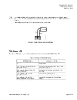
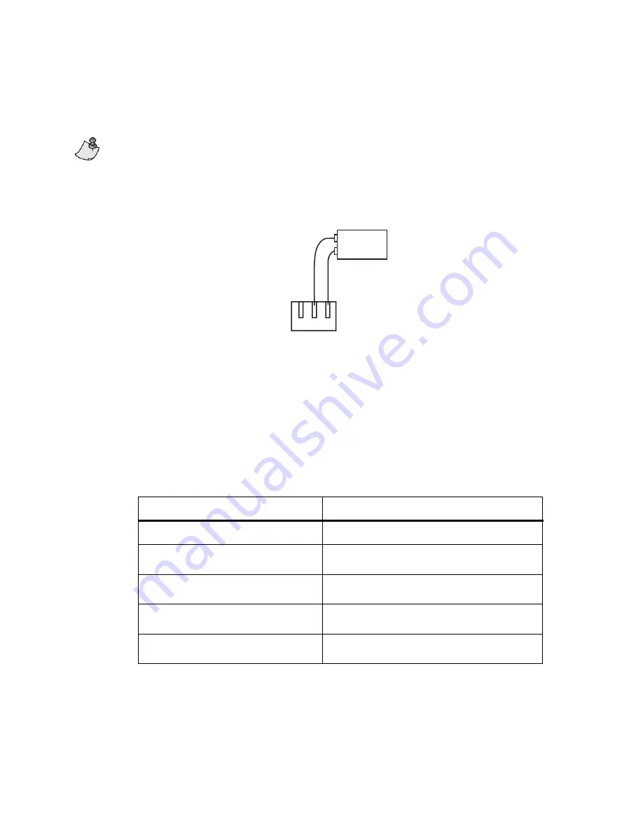
To temporarily power aTLX, such as for a site survey, you can use a common 9V battery. Use a
battery snap connector, available from a retail electronics store, and connect the battery as shown in
Figure 3.
The battery will power the TLX for approximately four to six hours.
WLAN0094R1
E
Red
Black
9 VDC
+
-
H N
Figure 3. Battery Snap Connector Wiring.
TLX Status LED
The Status LED indicates the current operation mode and communication status of the TLX.
Table 1. Status LED Blink Patterns.
LED Blink Pattern
Indicates the TLX is:
OFF Not
powered.
Green—quickly blinking ON and OFF
(every 0.25 second)
Powered; communicating with at least one node
(FPX, FLNX, WRTS).
Green—slowly blinking ON and OFF
(every 1.0 second)
Powered; but not currently communicating with
any nodes.
Yellow—blinking ON and OFF
(every 0.75 second)
Powered; running Energy Scan.
Yellow—blinking ON and OFF
(every 1.0 second) or ON steadily
Powered; but nonoperational. Contact Field
Support.

