


Transfer Control Device
Instructions
Order No.: 3ZX1012-0WX36-7JA1
English
3WX3666-7JA00
5
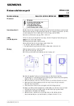
Warning Note
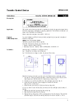
Application
The transfer control device can be used to implement automatic changeover between the nor-
mal mains supply and an emergency supply (e.g. generator). The transfer control device is an
accessory for the 3WN6 circuit-breakers.
Normal supply and emergency supply: 380 V / 400 V AC.
Standard
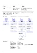
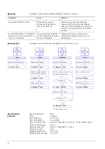
3WN6 Configuration
Two circuit-breakers with the following standard configuration are required to implement
automatic changeover:
3WN6
@
@
@
-
@
@
@
5 8 - 1 K A
@
.
The blank spaces
@
can be filled as required.
For further information on these circuit-breakers, see
• Manual, Order No. E20001-P285-A571
• Operating Instructions, Order No. 3ZX1812-0WN60-0AN1 / 9239 9757 174
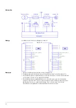
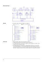
Installation
Wall mounting or installation in switchgear cubicle.
Fig. I: Dimensions for drilling, outer dimensions
Fig. II: Installation in switchgear cubicle, side view and front view
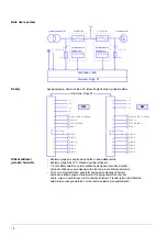
Note the following points when you choose to install the device in a switchgear cubicle:
1. You require, a mounting plate for example, to which the transfer control device can be
fixed.Dimensions: 320 mm x 400 mm, drilled holes as shown in Fig. I.
2. Provide a cut-out of 216 mm x 322 mm in the switchgear cubicle door (Fig. II).
3. Attach the mounting plate in the switchgear cubicle behind the door.
Spacing: 150 +/- 2 mm, Fig. II.
4. Screw the transfer control unit firmly onto the mounting plate.
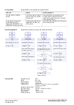
It is also possible to mount the transfer control device in the switchgear cubicle without a
housing:
1. Remove the hinge pin by dismantling the locking ring.
2. Separate the front panel from the housing.
3. Remove the mounting plate with the switching devices from the housing. The maximum
permitted length of the cable connecting the lamps and control switches is 100 cm.
WARNING:
HAZARDOUS VOLTAGE
CAN CAUSE ELECTRICAL SHOCK
AND BURNS.
DISCONNECT POWER BEFORE PROCEEDING
WITH ANY WORK ON THIS EQUIPMENT.
284
34
0
150
±
2
I
II
40
0
320
216
32
2
6
10


