background image

Operation

3ZX1012-0RB22-1AA1

15

English

4

Operation

4.1

Setting current and tripping category

The setting value of the motor current Ie is adjusted using two 

rotary buttons. One rotary button is used to set the maximum 

current I

MAX

 and the trip class (CLASS, 

Fig. IVa

), the other 

one sets the motor current between 10 and 100% of the 

selected maximum current I

MAX

 (

Fig. IVb

). For tripping 

characteristics, see 

Fig. IX

.

In case of > 40% asymmetry (acc. to NEMA) and phase 

failure, a tripping operation is executed acc. to 

Fig. X

. The 

characteristic curves are valid for cold starting. For starting 

with pre-loading, tripping times t

A

 are reduced.

Note

Motor, lines and contactor must be designed for the respective trip 
class (CLASS).

7

Prior to initial commissioning, check the CLASS 
setting! 

7

Using the rotary button for the trip classes
(CLASS), select the appropriate tripping
characteristic (see 

Fig. IV, IX and X

). 

Note

Using the sealable covering 3RB2984-2, you can protect the 
rotary buttons and the function expansion module against 
inadvertent operation. To do this, attach the cover (see graphic 
section 

Fig. III

). 

Summary of Contents for 3RB22

Page 1: ...o di sovraccarica Relé de sobrecarga electrónico Betriebsanleitung Operating Instructions Instructions de service Instructivo Istruzioni operative Instruções de Serviço Bestell Nr Order No N de réf Referencia N di ordinazione N º de Referência 3ZX1012 0RB22 1AA1 08 2006 GWA 4NEB 969 1645 10 DS 03 Last update 24 August 2006 PTB 05 ATEX 3022 II 2 GD ...

Page 2: ... 1x 1x 3RB2987 2B 0 1 m 3RB2987 2D 0 5 m 3RB2283 4AA1 mono 3RB2383 4AA1 bistable 3RB2283 4AC1 mono 3RB2383 4AC1 bistable Option Opción Opzione Opçaõ 3RB2985 2AA0 MODUL ANALOG BASIC 1 3RB2985 2AA1 MODUL ANALOG BASIC 1 GF 3RB2985 2AB1 MODUL ANALOG BASIC 2 GF 3RB2985 2CA1 MODUL BASIC 1 GF 3RB2985 2CB1 MODUL BASIC 2 GF 3ZX1012 0RB22 1AA1 ...

Page 3: ...I 86 5 36 5 45 7 2 80 91 5 118 5x37 138 5x37 2 9 7 2 87 98 5 6 a b c d 102 3RB2 83 4AA1 3RB2 83 4AC1 a 65 b 36 c 95 99 d 106 110 3ZX1012 0RB22 1AA1 ...

Page 4: ...C1 5 6 mm PZ2 0 8 1 2 Nm 7 to 10 3 lb in 1 x 0 5 4 0 mm 2 x 0 5 2 5 mm 2 x 0 25 1 5 mm 1 x 0 5 2 5 mm 2 x 0 5 1 5 mm 2 x 0 25 1 5 mm 2 x 0 25 1 5 mm AWG 2 x 20 to 14 2 x 24 to 16 10 10 10 d b a 1 U 0 V 2 a b c d 3ZX1012 0RB22 1AA1 ...

Page 5: ...3RP1903 A C D Coded Codé Cifrado Codificato Codificado A C D Kodiert III 4 4 3RB2984 2 2 3 1 5 2 3 5 4 10 10 1 DIN ISO 2380 1A 0 5 x 3 3mm 3ZX1012 0RB22 1AA1 ...

Page 6: ... 15 xIM A X 1 0 0 A 20 10 5 30 20 10 5 30 20 10 5 30 10 5 30 20 10 0 0 A A 0 1 1 A OVERLOAD RESET MAN AUTO READY GND FAULT THERMISTOR TEST RESET ANALOGI I G N DF A ULT05 0 6 G N DF A ULT95 9 6 OL Warn05 06 OL Trip 95 96 98 08 07 97 Y1 T1 96 06 05 95 I T2 I SIRIUS 3RB2283 4AA1 A124 240VA2 G JJMMTT Exx Y2 IV 3RB2985 2CB1 3RB2985 2CA1 3RB2985 2AA0 3RB2985 2AB1 3RB2985 2AA1 1 2 3 4 5 6 IVa IVb 100A CL...

Page 7: ...V 3ZX1012 0RB22 1AA1 ...

Page 8: ...L1 3RB29 6 2 H2 L2 L3 T1 T2 T3 M 1 L N 3RB22 3RB23 L1 VI M 1 VII Imotor NO1 NC1 0 5 s ttrip 1 s 10 x Ie 8 0 3 1 2 3 4 5 6 7 9 I trip_GF 0 3 0 6 0 9 1 2 x Ie Tripping area 1 3RB2985 2CA1 2AA1 NC 95 96 NO 97 98 3RB2985 2CB1 2AB1 NC 05 06 NO 07 08 3ZX1012 0RB22 1AA1 ...

Page 9: ... K1E ON S1 K1E PE U V W A1 A2 96 05 95 K2 F2 T1 T2 A2 A1 READY GND FAULT THER MISTOR OVER LOAD RESET AUTO MAN Ground Fault CLASS 5 10 20 30 K1 F6 OFF S2 Y1 Y2 REMOTE RESET I I 4 20 mA K1E 98 07 06 97 08 3RB29 6 3RB22 23 3RB2985 6A gL gG 3RB2987 2 VIII 3ZX1012 0RB22 1AA1 ...

Page 10: ...10 20 50 1 2 5 8 0 7 1 2 5 10 20 50 100 120 s min 10 5 CLASS CLASS 30 20 x Ie 1 2 5 10 20 50 1 2 5 8 0 7 1 2 5 10 20 50 100 120 s min 10 5 CLASS CLASS 30 20 X 3 Phasen 3 phase 2 Phasen 2 phase t A 3ZX1012 0RB22 1AA1 x Ie ...

Page 11: ...vergleicht den durch das Stromerfassungsmodul flie ßenden aktuellen Motorstrom mit dem Einstellwert verarbeitet die Werte in einem Mikrocontroller und löst im Bedarfsfall aus Thermistor schutz Kaltleitertemperaturfühler Thermistoren in der Motorwicklung erfassen die Temperatur des Motors Wird die durch die Thermis toren bestimmte Temperatur überschritten löst das Relais aus Die Thermistoren werden...

Page 12: ... mit Einstecklaschen als Zubehör 3RP1903 Bild III 3 Anschluss Der Motorstrom wird mit dem Stromerfassungsmodul 3RB29 ermit telt Der Anschluss der Motorzuleitungen ist in der Betriebsanlei tung 3ZX1012 0RB00 1AA1 beschrieben Das elektronische Überlas trelais wird durch ein Flachbandkabel 3RB2987 mit dem Strom erfassungsmodul verbunden Bild VIII Anschlussquerschnitte und drehmomente siehe Tabelle Bi...

Page 13: ...rfolgt eine Auslösung nach Bild X Die Kennlinien gelten für einen Kaltstart Bei einem Start mit Vorbelastung reduzieren sich die Auslösezeiten tA Hinweis Motor Leitungen und Schütz müssen für die entsprechende Aus löseklasse CLASS ausgelegt sein 7 Kontrollieren Sie vor der ersten Inbetriebnahme die CLASS Einstellung 7 Wählen Sie mit dem Drehknopf für die Auslöse klassen CLASS die entsprechende Aus...

Page 14: ...n Anwendertest kann der Status der Thermistorauswertung aktiviert deaktiviert überprüft werden Deaktivierung Halten Sie während des Einschaltens der Steuerspannung A1 A2 den TEST RESET Knopf gedrückt leuchtet die THERMIS TOR LED auf Lassen Sie jetzt innerhalb von 3 s den Knopf los ist die Thermistorfunktion deaktiviert Dies wird durch Aufblitzen der THERMISTOR LED im 10 s Intervall angezeigt Achtu...

Page 15: ...LT rotes Dauerlicht 05 06 95 962 öffnet 07 08 97 982 schließt Thermistor deaktiviert THERMISTOR rotes Blitzen im 10 s Intervall Thermistor Auslösung THERMISTOR rotes Dauerlicht 95 96 öffnet 97 98 schließt Überlast Warnung1 3 ab 1 13 x Ie OVERLOAD rotes Flimmern 05 06 öffnet 07 08 schließt Überlast Auslösung OVERLOAD rotes Dauerlicht 95 96 öffnet 97 98 schließt Anwendertest siehe 4 5 siehe 4 5 Gerä...

Page 16: ...r Drahtbruch Anschluss unterbrochen Unterbrechung beseitigen 4 5 Kommunikation zum Stromerfassungsmodul während des Starts feh lerhaft Ist das Stromerfassungsmodul angeschlossen 6 Zuordnung Ie Stromerfassungsmodul falsch Der eingestellte Strom Ie liegt außerhalb des zulässigen Strombe reichs des Stromerfassungsmoduls oder Drehknopf Bild IVb außer halb 10 100 Bitte korrigieren 7 Ungültiges Stromerf...

Page 17: ...itet die Abschaltung der Relais ein Bis zu diesem Zeitpunkt kann der Anwendertest ohne Abschaltung der Relais abgebrochen werden Test phase Dauer Beschreibung Bemerkung 1 3 s Anzeigentest prüfen ob alle LEDs blinken 2 3 s Konfigurationstest1 Aktivierte Funktionen werden durch Flimmern der entsprechenden LEDs angezeigt Dabei steht die READY LED für die Autoreset Funk tion 3 18 s Interne Tests Syste...

Page 18: ...98 05 06 07 08 READY1 GND FAULT THERMISTOR OVERLOAD Testphase 1 2 3 4 0 3 6 9 12 15 18 21 24 LED leuchtet LED blinkt LED flimmert LED aus aktiv geschlossen inaktiv offen 1 Während des Tests zeigt die READY LED die Autoreset Funktion an TEST RESET t s ...

Page 19: ...in denen der unerwartete Neustart des Motors zu Personen oder Sachschäden führen kann Wenn das 3RB22 23 ausgelöst hat durch dann setzen Sie das Überlastrelais nach folgenden Zeiten zurück durch kurzes Drücken der Test Reset Taste Fern Reset Taster an Y1 Y2 kurz betätigen Automatik Reset Schalter2 Test sofort Überlast1 nach 3 min Thermistor1 wenn 5 K unter Ansprechtemperatur erreicht sind Erdschlus...

Page 20: ...Störaussendung nach EN 55011 Grenzwertklasse A Gewicht 235 g Zulässige Umge bungstemperatur 25 bis 60 C Lagerfähigkeit 40 bis 80 C Hauptstromkreis siehe Katalog Stromerfassungsmodul Bemessungs steuerspeise spannung US Arbeitsbereich AC 50 60 Hz 24 V bis 240 V 0 85 bis 1 1 x Us DC 24 V bis 240 V 0 85 bis 1 1 x Us Kontakt bestückung 2 x 1 S 1 Ö Galvanische Trennung der Hilfsschalter potentialfrei si...

Page 21: ...ckfallwert 1 5 bis 1 65 kΩ Kurzschlusserkennung 10 bis 20 Ω Erdschluss schutz Die folgenden Angaben beziehen sich auf sinusförmige Fehler ströme von 50 60 Hz Bei einem Motorstrom zwischen dem 0 3 und dem 2 fachen Einstell strom Ie löst das Gerät bei einem Erdschlussstrom der 30 vom Einstellstrom beträgt aus Bei einem Motorstrom zwischen dem 2 und dem 8 fachen Einstell strom Ie löst das Gerät bei e...

Page 22: ...d IV 4 bis 20 mA 1 x Ie 0 128 mA Beispiel Iout 10 40 mA Ie 6 0 A I 50 von Ie Imotor 3 A Technische Daten max Ausgangsstrom 20 mA Klemmen I und I max Bürde 100 Ω Genauigkeit 10 kurzschluss und leerlauffest 0 mA 4 mA 8 mA 12 mA 16 mA 20 mA 24 mA 0 xIe 20 xIe 40 xIe 100 xIe 60 xIe 80 xIe 16 8mA I Ie Iout 4 mA 0 128 mA Imotor A Iout 4 mA x Ie 12 8 mA Iout mA Imotor x 12 8 mA Ie 4 mA ...

Page 23: ...protection The relay compares the momentary motor current flowing through the current measurement module with the set value processes these values in a microcontroller and releases if necessary Thermistor protection PTCs thermistors in the motor winding measure the motor temperature If the temperature specified by the thermistor is exceeded the relay will trip The thermistors are monitored for sho...

Page 24: ...e or 7 Screw mounting with push in lugs as accessory 3RP1903 Fig III 3 Connection The motor current is measured with the 3RB29 current measurement module The connection of the motor lines is described in the operating manual 3ZX1012 0RB00 1AA1 The electronic overload relay is connected with the current measurement module using a ribbon cable 3RB2987 Fig VII Conductor cross sections and torques in ...

Page 25: ...MA and phase failure a tripping operation is executed acc to Fig X The characteristic curves are valid for cold starting For starting with pre loading tripping times tA are reduced Note Motor lines and contactor must be designed for the respective trip class CLASS 7 Prior to initial commissioning check the CLASS setting 7 Using the rotary button for the trip classes CLASS select the appropriate tr...

Page 26: ...l will be output The user test serves to check the thermistor evaluation activated deactivated status Deactivation If the TEST RESET button is pressed while the control voltage A1 A2 is switched on the THERMISTOR LED will light up Releasing the button within 3 s will deactivate the thermistor function This will be shown by the THERMISTOR LED flashing in 10 s intervals Notice To ensure reliable fun...

Page 27: ... optional1 GND FAULT cont red light 05 06 95 962 opens 07 08 97 982 closes Thermistor deactivated THERMISTOR red flashes at 10 s interval Thermistor tripping THERMISTOR cont red light 95 96 opens 97 98 closes Overload warning1 3 from 1 13 x Ie OVERLOAD red flickering 05 06 opens 07 08 closes Overload tripping OVERLOAD cont red light 95 96 opens 97 98 closes User test Refer to 4 5 Refer to 4 5 Unit...

Page 28: ...istor fault Wire break Connection broken Remove interruption 4 5 Faulty communication with current measurement module during start up Is the current measurement module connected 6 Faulty assignment of Ie current measurement module Set current Ie not within the permissible current range of the current measurement module or rotary button Fig IVb outside 10 100 Please correct 7 Invalid current measur...

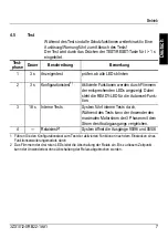
Page 29: ...d LEDs initiates the relay switch off Up to this moment it is possible to abort the user test without switching off the relays Testing phase Dura tion Description Comment 1 3 s LED test Check whether all LEDs are flashing 2 3 s Configuration test1 Activated functions are indicated by flickering of the respective LEDs The READY LED stands for the autoreset function 3 18 s Internal tests System exec...

Page 30: ...97 98 05 06 07 08 READY1 GND FAULT THERMISTOR OVERLOAD Testphase 1 2 3 4 0 3 6 9 12 15 18 21 24 LED lights up LED flashes LED flickers LED off active closed inactive open 1 During testing the READY LED indicates the autoreset function TEST RESET t s ...

Page 31: ...d restart of the motor may lead to personal injury or damage to property If the 3RB22 23 has tripped due to then reset the overload relay after the following intervals by briefly pressing the test reset button remote reset briefly press button at Y1 Y2 automatic reset switch2 Test Immediately Overload1 After 3 min Thermistor1 When the temperature is 5 K below the operating temperature Ground fault...

Page 32: ...1000 4 5 1 2 kV Interfer emission acc to EN 55011 limit value class lim class A Weight 235 g Rated control supply voltage US Operating range AC 50 60 Hz 24 V to 240 V 0 85 to 1 1 x Us DC 24 V to 240 V 0 85 to 1 1 x Us Permissible ambient temperature 25 up to 60 C Storage temperature 40 to 80 C Contact equipment 2 x 1 NO 1 NC Galvanic isolation of the auxiliary switches floating safe isolation at U...

Page 33: ... Operating value overload 3 4 to 3 8 kΩ Release value 1 5 to 1 65 kΩ Short circuit detection 10 to 20 Ω Ground fault protection The following data refers to sinusoidal fault currents of 50 60 Hz With a motor current between the 0 3 and 2 fold set currentIe the unit trips at an ground fault current that is 30 of the set current With a motor current between the 2 and 8 fold set currentIe the unit tr...

Page 34: ... mA 1 x Ie 0 128 mA Example Iout 10 40 mA Ie 6 0 A I 50 of Ie Imotor 3 A Technical data Max output current 20 mA Terminals I and I max burden 100 Ω Accuracy 10 Short circuit proof and resistant to no load operation 0 mA 4 mA 8 mA 12 mA 16 mA 20 mA 24 mA 0 xIe 20 xIe 40 xIe 100 xIe 60 xIe 80 xIe 16 8mA I Ie Iout 4 mA 0 128 mA Imotor A Iout 4 mA x Ie 12 8 mA Iout mA Imotor x 12 8 mA Ie 4 mA ...

Page 35: ...on contre les surcharges Le relais compare le courant de moteur actuel détecté à l aide du module de mesure de courant et une valeur de réglage traite les valeurs dans un microcontrôleur et le cas échéant procède au déclenchement Protection par thermistance Des sondes PTC thermistances de l enroulement du moteur détectent la température du moteur Le relais se déclenche au dépassement de la tempéra...

Page 36: ...ion par encliquetage avec des pattes d enfichage pour accessoires 3RP1903 figure III 3 Raccordement Le courant du moteur est saisi à l aide du module de mesure de courant 3RB29 Le raccordement des câbles d arrivée du moteur est décrit dans les instructions de service 3ZX1012 0RB00 1AA1 Le relais de surcharge électronique est relié au moyen d un câble plat 3RB2987 au module de mesure de courant fig...

Page 37: ... figure X Les caractéristiques conviennent pour un démarrage à froid Les temps de déclenchement tA sont réduits pour un démarrage avec pré charge Remarque Le moteur les câbles et le contacteur doivent être conçus pour la classe de déclenchement respective 7 Contrôlez avant la première mise en service le réglage CLASS et veuillez le corriger le cas échéant 7 Sélectionnez à l aide du bouton rotatif ...

Page 38: ...r l état de l analyse de la thermistance activée désactivée Désactivation La LED THERMISTOR s allume au maintien du bouton TEST RESET à la mise sous tension de la tension de commande A1 A2 La fonction de thermistance se désactive ensuite si le bouton est relâché dans les 3 secondes ce qui est signalé par le clignotement de la LED THERMISTOR toutes les 10 secondes Important Afin de pouvoir garantir...

Page 39: ...tion1 GND FAULT feu fixe rouge 05 06 95 962 ouvert 07 08 97 982 se ferme Thermistance désactivée THERMISTOR clignot rouge toutes les 10 s Déclenchement thermis tance THERMISTOR feu fixe rouge 95 96 ouvert 97 98 se ferme Alarme de surcharge1 3 à partir de 1 13 x Ie OVERLOAD scintillement rouge 05 06 s ouvre 07 08 se ferme Déclenchement de surcharge OVERLOAD feu fixe rouge 95 96 s ouvre 97 98 se fer...

Page 40: ...e de connexion Eliminer la rupture 4 5 Communication vers le module de mesure de courant défectueuse pendant le démarrage Le module de mesure de courant est il raccordé 6 Affectation Ie module de mesure du courant incorrect le courant réglé Ie se trouve hors de la plage de courant admissible du module de mesure du courant ou le bouton tournant fig IVb se situe hors de la plage 10 à 100 Veuillez co...

Page 41: ... Préalablement à cet événement le test utilisateur peut être interrompu sans déclenchement du relais Phase test Durée Description Remarque 1 3 s Test de signalisation Vérifier le bon clignotement de toutes les LED 2 3 s Test de configuration1 Les fonctions activées sont signalées par le scintillement des LED correspondantes La LED READY désigne la fonction Autoreset 3 18 s Tests internes Le systèm...

Page 42: ...7 98 05 06 07 08 READY1 GND FAULT THERMISTOR OVERLOAD Phase test 1 2 3 4 0 3 6 9 12 15 18 21 24 LED allumée LED clignote LED scintille LED éteinte actif fermé inactif ouvert 1 La LED READY affiche la fonction Autoreset pendant le test TEST RESET t s ...

Page 43: ...er des lésions ou des dommages matériels importants En cas de déclenchement du 3RB22 23 par réarmer le relais de surcharge après les laps de temps suivants en appuyant brièvement sur la touche Test Reset en exécutant un reset à distance actionner brièvement le bouton Y1 Y2 en exécutant un reset automatique commutateur2 Test immédiatement Surcharge1 après 3 minutes Thermistance1 lorsque la températ...

Page 44: ...0 4 5 1 2 kV Emissions parasites selon EN 55011 classe de valeur limite A Poids 235 g Tension assignée d alimentation de commande Uc Plage de tension CA 50 60 Hz 24 V à 240 V 0 85 à 1 1 x Uc CC 24 V à 240 V 0 85 à 1 1 x Uc Température ambiante admissible 25 à 60 C Capacité de stockage 40 à 80 C Equipement des contacts 2 x 1 NO 1 NF Séparation galva nique des blocs de contacts auxi liaires libres d...

Page 45: ...ge 3 4 à 3 8 kΩ Seuil de retombée 1 5 à 1 65 kΩ Détection de court circuit 10 à 20 Ω Protection de défaut à la terre Les informations suivantes correspondent aux courants d erreur sinusoïdaux de 50 60 Hz Pour un courant de moteur entre 0 3 et le double du courant de réglage Ie l appareil se déclenche pour un courant de défaut à la terre de 30 du courant de réglage Pour un courant de moteur entre l...

Page 46: ...a figure IV 4 à 20 mA 1 x Ie 0 128 mA Exemple Iout 10 40 mA Ie 6 0 A I 50 de Ie Imoteur 3 A Caractéristiques techniques Courant de sortie max 20 mA Bornes I et I Charge max 100 Ω Précision 10 Tenue aux courts circuits et à vide 0 mA 4 mA 8 mA 12 mA 16 mA 20 mA 24 mA 0 xIe 20 xIe 40 xIe 100 xIe 60 xIe 80 xIe 16 8mA I Ie Iout 4 mA 0 128 mA Imotor A Iout 4 mA x Ie 12 8 mA Iout mA Imotor x 12 8 mA Ie ...

Page 47: ... el módulo de medida de corriente a partir del valor de ajuste procesa los correspondientes valores con el microcontrolador integrado y si es necesario provoca el disparo Protección de termistor Los termistores integrados en el arrollamiento miden la temperatura del motor El relé reacciona en el momento de rebasar el nivel de temperatura especificado en los termistores El relé detecta los cortocir...

Page 48: ...a III 3 Conexión La corriente de motor se mide por medio del módulo de medida de corriente 3RB29 El esquema de conexiones de los cables del motor se describe en el manual de instrucciones 3ZX1012 0RB00 1AA1 Para establecer la conexión entre el relé de sobrecarga electrónico y el módulo de medida de corriente se utiliza un cable plano 3RB2987 figura VIII Las secciones y pares de conexión se detalla...

Page 49: ...A y falta de fase se provoca el disparo tal y como se indica en la figura X Se indican las características en condiciones de arranque en frío Al arrancar en caliente se reducen los tiempos de disparo tA Nota El motor los cables y el contactor deben ser preparados para la correspondiente categoría de disparo CLASS 7 Antes de la primera puesta en funcionamiento se debe comprobar el ajuste de la CLAS...

Page 50: ...unción de evaluación de termistores activada desactivada se puede verificar por medio del test de aplicación Desactivar Manteniendo pulsado el botón TEST RESET al encender la tensión de control A1 A2 se ilumina el LED TERMISTOR Para desactivar la función de evaluación de termistores suelte dicho botón antes de transcurrir 3 segundos Ese estado se confirma parpadeando el LED TERMISTOR en intervalos...

Page 51: ... continua 05 06 95 962 abriendo 07 08 97 982 cerrando Termistor desactivado TERMISTOR flash rojo a intervalos de10 s Disparo termistor TERMISTOR luz roja continua 95 96 abriendo 97 98 cerrando Aviso sobrecarga1 3 a partir de 1 13 x Ie OVERLOAD centelleo rojo 05 06 abriendo 07 08 cerrando Disparo por sobrecarga OVERLOAD luz roja continua 95 96 abriendo 97 98 cerrando Test de aplicación ver 4 5 ver ...

Page 52: ...e cable Corte de conexión Eliminar la causa del corte 4 5 Falta de comunicación con el módulo de medida de corriente durante el arranque Módulo de medida de corriente conectado 6 Asignación Ie módulo de medida de corriente errónea Valor Ie fuera del rango de corriente admisible del módulo de medida de corriente o bien selector fig IVb fuera del rango del 10 100 Ajustar los valores correctos 7 Dete...

Page 53: ...exión inminente de los relés Hasta ese momento el usuario puede cancelar el test de aplicación sin desconectar los relés Fase test Dura ción Descripción Observaciones 1 3 s Test visualización comprobar si los LED parpadean 2 3 s Test configuración1 El estado de activado de una función se señaliza centelleando el correspondiente LED El LED READY señaliza la función de autoreset 3 18 s Tests interno...

Page 54: ...8 05 06 07 08 READY1 GND FAULT THERMISTOR OVERLOAD Testphase 1 2 3 4 0 3 6 9 12 15 18 21 24 LED ilumin LED parpadeando LED centell LED apagado activado cerrado desactivado abierto 1 Durante el test el LED READY señaliza la función de autoreset TEST RESET t s ...

Page 55: ...o del motor pueda causar daños materiales o personales Disparo del 3RB22 23 por Resetear el relé de sobrecarga transcurridos los siguientes intervalos pulsando brevemente el botón Test Reset Reset a distancia pulsar brevemente el botón en Y1 Y2 Reset automático selector2 Test inmediatamente Sobrecarga1 transcurridos 3 min Termistor1 alcanzando un nivel de 5 K debajo de la temperatura de reacción F...

Page 56: ...61000 4 5 1 2 kV Interferencias según EN 55011 categoría A Peso 235 g Tensión de alimentación de control asignada US Rango de funcionamiento AC 50 60 Hz 24 V a 240 V 0 85 a 1 1 x Us DC 24 V a 240 V 0 85 a 1 1 x Us Temperatura ambiente admisible 25 a 60 C Temperatura de almacenaje 40 a 80 C Equipamiento de contactos 2 x 1 NA 1 NC Separación galvánica de contactos auxiliares libre de potencial separ...

Page 57: ...n de cortocircuito 10 a 20 Ω Protección contra faltas de tierra Los siguientes datos aplican para corrientes residuales senoidales de 50 60 Hz Con una corriente de motor que equivale 0 3 hasta 2 veces la corriente de ajuste Ie el dispositivo dispara al alcanzar un nivel de la corriente de falta de tierra que equivale el 30 de la corriente de ajuste Con una corriente de motor que equivale 2 hasta 8...

Page 58: ...20 mA 1 x Ie 0 128 mA Ejemplo Iout 10 40 mA Ie 6 0 A I 50 de Ie Imotor 3 A Datos técnicos Corriente de salida máx 20 mA Bornes I e I Carga máx 100 Ω Precisión 10 Resistente al cortocircuito y la marcha en vació 0 mA 4 mA 8 mA 12 mA 16 mA 20 mA 24 mA 0 xIe 20 xIe 40 xIe 100 xIe 60 xIe 80 xIe 16 8mA I Ie Iout 4 mA 0 128 mA Imotor A Iout 4 mA x Ie 12 8 mA Iout mA Imotor x 12 8 mA Ie 4 mA ...

Page 59: ...richi Il relè confronta la corrente di motore attuale che scorre attraverso il modulo di rilevamento della corrente con il valore impostato elabora i valori in un microcontrollore e in caso di necessità si sgancia Protezione tramite termistori Termosonde termistori nell avvolgimento del motore rilevano la tempe ratura del motore Se si supera la temperatura stabilita dai termistori il relè si sganc...

Page 60: ...unti inseribili come accessorio 3RP1903 figura III 3 Collegamento La corrente del motore viene rilevata con il modulo di rilevamento della corrente 3RB29 Il collegamento dell alimentazione del motore è descritto nel manuale operativo 3ZX1012 0RB00 1AA1 Il relè elettronico di sovraccarico viene collegato al modulo 3RB2987 di rilevamento della corrente tramite un cavo a nastro piatto figura VIII Sez...

Page 61: ...caduta di fase avviene uno sgancio secondo la figura X Le caratteristiche valgono per un avviamento a freddo In caso di avviamento con precarico si riducono i tempi di sgancio tA Indicazione Motore cavi e contattori devono essere configurati per la classe di sgancio CLASS corrispondente 7 Prima della prima messa in servizio controllate l im postazione CLASS 7 Selezionate con la manopola delle clas...

Page 62: ...Lo stato della valutazione del termi store può essere verificato tramite il test di usabilità attivato disattivato Disattivazione se durante l attivazione della tensione di comando A1 A2 si tiene pre muto il tasto TEST RESET si illumina il LED THERMISTOR Se ora entro 3 s rilasciate il pulsante la funzione termistori è disattivata Ciò viene indi cato tramite lo scintillio del LED THERMISTOR in inte...

Page 63: ...a opzionale1 GND FAULT luce rossa continua 05 06 95 962 apre 07 08 97 982 chiude Termistore disattivato TERMISTORE lampeggiare rosso ad intervalli di 10 s Sgancio del termistore TERMISTORE luce rossa continua 95 96 apre 97 98 chiude Allarme sovraccarico1 3 da 1 13 x Ie OVERLOAD sfarfallio rosso 05 06 apre 07 08 chiude Sgancio di sovraccarico OVERLOAD luce rossa continua 95 96 apre 97 98 chiude Tes...

Page 64: ...interruzione 4 5 Comunicazione difettosa con il modulo di rilevamento della corrente durante l avviamento Il modulo di rilevamento della corrente è collegato 6 Assegnazione Ie modulo di rilevamento della corrente scorretta la corrente impostata Ie è al di fuori del campo di corrente ammissibile del modulo di rilevamento della corrente o manopola fig IVb al di fuori di 10 100 Pregasi di correggere ...

Page 65: ... il disinserimento dei relè Fino a questo punto il test di usabilità può essere interrotto senza disinserire i relè Fase di test Durata Descrizione Nota 1 3 s Test di visualizzazione Verificare se tutti i LED lampeggiano 2 3 s Test della configurazione1 Le funzioni attivate vengono indicate tramite sfarfallio dei LED corrispondenti Il LED READY sta qui ad indicare la funzione di autoreset 3 18 s T...

Page 66: ...05 06 07 08 READY1 GND FAULT THERMISTOR OVERLOAD Fase di test 1 2 3 4 0 3 6 9 12 15 18 21 24 LED si illumina LED lampeggia LED sfarfalla LED spento attivo chiuso inattivo aperto 1 Durante il test il LED READY indica la funzione di autoreset TEST RESET t s ...

Page 67: ...mprovviso del motore può causare danni alle persone o alle cose Se il 3RB22 23 si è sganciato tramite Ripristinate il relè di sovraccarico secondo i seguenti tempi tramite premere breve mente il tasto Test Reset reset a distanza attivare breve mente tasto a Y1 Y2 reset automatico interruttore2 Test subito Sovraccarico1 dopo 3 min Termistore1 se sono stati raggiunti 5 K sotto la temperatura di risp...

Page 68: ...C 61000 4 5 1 2 kV Emiss di interferenze sec EN 55011 classe valore limite A Peso 235 g Tensione nominale di comando US Campo operativo AC 50 60 Hz 24 V fino 240 V 0 85 fino 1 1 x Us DC 24 V fino 240 V 0 85 fino 1 1 x Us Temperatura ambiente ammissibile 25 fino 60 C Conservabilità 40 fino 80 C Contatti 2 x 1 NO 1 NC Separazione gal vanica dei con tatti ausiliari a potenziale libero separazione sic...

Page 69: ...no 3 8 kΩ Valore di scatto 1 5 fino 1 65 kΩ Riconoscimento di cortocircuito 10 fino 20 Ω Protezione di guasto a terra I seguenti dati si riferiscono a correnti di guasto di forma sinusoidale di 50 60 Hz Con una corrente del motore tra lo 0 3x e il 2x della corrente di regolazione Ie in presenza di una corrente verso terra pari al 30 della corrente di regolazione il dispositivo si sgancia Con una c...

Page 70: ...V 4 fino 20 mA 1 x Ie 0 128 mA esempio Iout 10 40 mA Ie 6 0 A I 50 di Ie IMotore 3 A Dati tecnici Corrente d uscita max 20 mA Morsetti I e I Carico max 100 Ω Precisione 10 Resistente al cortocircuito e al funzionamento a vuoto 0 mA 4 mA 8 mA 12 mA 16 mA 20 mA 24 mA 0 xIe 20 xIe 40 xIe 100 xIe 60 xIe 80 xIe 16 8mA I Ie Iout 4 mA 0 128 mA Imotor A Iout 4 mA x Ie 12 8 mA Iout mA Imotor x 12 8 mA Ie 4...

Page 71: ...tual do motor que passa pelo módulo de levantamento de dados de corrente com o valor ajustado processa os valores num microcontrolador e inicia em caso de necessidade Proteção do termistor Sensor de resistor com coeficiente positivo de temperatura termistores na bobinagem do motor levantam os dados da temperatura do motor Se a temperatura determinada pelos termistores for ultrapassada o relé é ati...

Page 72: ... talas de encaixe como acessório 3RP1903 figura III 3 Conexão A corrente do motor é apurada através do módulo de levantamento de dados de corrente 3RB29 A conexão das linhas adutoras do motor está descrita na instrução de serviço 3ZX1012 0RB00 1AA1 O relé eletrônico de sobrecarga está ligado ao módulo de levantamento de dados de cor rente através de um cabo plano 3RB2987 figura VIII Seções transve...

Page 73: ...ase resulta uma iniciação segundo figura X As características internas valem para um inicio a frio Em caso de inicio com polarização reduzem se os tempos de iniciação tA Indicação O motor os condutores e o contator devem estar dimensionados para o respectivo grau de iniciação CLASS 7 Controle o ajuste CLASS antes da primeira colocação em serviço 7 Selecione a respectiva característica interna de i...

Page 74: ...um erro O estado da avaliação do termistor ativado desativado pode ser revisado através do teste do usuário Desativação Mantenha o botão TEST RESET pressionado durante a ligação da tensão de comando A1 A2 o LED TERMISTOR se acende Solte agora o botão dentro de 3 s a função termistor está desativada Isto é sinalizado através da piscagem do LED TERMISTOR num intervalo de 10 s Atenção Para garantir u...

Page 75: ... GND FAULT luz perm vermelha 05 06 95 962 abre 07 08 97 982 fecha Termistor desativado TERMISTOR piscagem vermelha num intervalo de 10 s Iniciação termistor TERMISTOR luz permanente vermelha 95 96 abre 97 98 fecha Advertência de sobre carga1 3 a partir de 1 13 x Ie OVERLOAD cintilação vermelha 05 06 abre 07 08 fecha Iniciação de sobrecarga OVERLOAD luz permanente vermelha 95 96 abre 97 98 fecha Te...

Page 76: ... interrupção 4 5 Comunicação ao módulo de levantamento de dados de corrente durante o arranque com erro Está conectado o módulo de levantamento de dados de corrente 6 Alocação Ie módulo de levantamento de dados de corrente errado A corrente Ie ajustada está fora da área de corrente permitida do módulo de levantamento de dados de corrente ou o botão rotativo fig IVb fora de 10 100 Favor corrigir 7 ...

Page 77: ...vermelhos iniciam a desconexão do relé Até este instante o teste de usuário pode ser interrompido sem desconexão do relé Fasede teste Duração Descrição Comentário 1 3 s Teste de indicações verificar se todos os LEDs piscam 2 3 s Teste de configuração1 Funções ativadas são indicadas através da cintilação dos respectivos LEDs Nisso o LED READY está para a função Autoreset 3 18 s Testes internos O si...

Page 78: ...6 97 98 05 06 07 08 READY1 GND FAULT THERMISTOR OVERLOAD Fase de teste 1 2 3 4 0 3 6 9 12 15 18 21 24 LED brilha LED pisca LED cintila LED desligado ativo fechado inativo aberto 1 Durante o teste o LED READY indica a função Autoreset TEST RESET t s ...

Page 79: ... do motor pode levar a danos pessoais ou materiais Quando o 3RB22 23 foi iniciado através de então reponha o relé de sobrecarga depois dos seguintes tempos através de pressão curta do botão Test Reset Reset à distância operação curta da tecla Y1 Y2 Reset automático interruptor2 Teste imediatamente Sobrecarga1 após 3 min Termistor1 quando foram alcançados 5 K abaixo da temperatura de atuação Contat...

Page 80: ... 1 2 kV Envio de interfer na seg EN 55011 grau de límite de valor A Peso 235 g Tensão de alimentação de comando nominal US Área de trabalho AC 50 60 Hz 24 V até 240 V 0 85 até 1 1 x Us DC 24 V até 240 V 0 85 até 1 1 x Us Temperatura ambiente permitida 25 até 60 C Capacidade de armazenagem 40 até 80 C Inserção de contatos 2 x 1 S 1 Ö Separação galvâ nica dos interrup tores auxiliares livres de pote...

Page 81: ...e atuação sobrecarga 3 4 até 3 8 kΩ Valor de desoperação 1 5 até 1 65 kΩ Reconhecimento de curto circuito 10 até 20 Ω Proteção contato à terra Os seguintes dados correspondem a correntes de erros sinosoidais de 50 60 Hz Numa corrente de motor entre 0 3 e a dupla corrente ajustada Ie o aparelho inicia numa corrente de contato à terra que comporta 30 da corrente ajustada Numa corrente de motor entre...

Page 82: ... mA 1 x Ie 0 128 mA Exemplo Iout 10 40 mA Ie 6 0 A I 50 de Ie Imotor 3 A Dados técnicos Corrente de saída máx 20 mA Bornes I e I resistência máx de trabalho 100 Ω Exatidão 10 Teste de curto circuito e circuito aberto 0 mA 4 mA 8 mA 12 mA 16 mA 20 mA 24 mA 0 xIe 20 xIe 40 xIe 100 xIe 60 xIe 80 xIe 16 8mA I Ie Iout 4 mA 0 128 mA Imotor A Iout 4 mA x Ie 12 8 mA Iout mA Imotor x 12 8 mA Ie 4 mA ...

Page 83: ...2 1AA1 Änderungen vorbehalten Printed in the Federal Republic of Germany Changes without prior notice Zum späteren Gebrauch aufbewahren Store for use at a later date Technical Assistance Telephone 49 0 911 895 5900 8 17 CET Fax 49 0 911 895 5907 E mail technical assistance siemens com Internet www siemens de lowvoltage technical assistance Technical Support Telephone 49 0 180 50 50 222 www siemens...

Reviews: