background image

13 / 18

Siemens

Room temperature controller radio set REV24RF../SET

CE1N2206en

Building Technologies

2018-11-07

e)

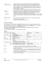
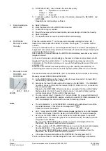
RCR10/868: LED_1 also indicates the radio link quality:

Red

=   Insufficient or no radio link

Orange  =   Good
Green  =   

Very good

f)

If radio link quality is insufficient, shorten the distance between the REV24RF.. and
RCR10/868.
Repeat the test until quality is sufficient.

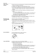
a)  Switch off power.
b)  Mark the place where the RCR10/868 is located.
c)  Loosen the wiring as needed.
d)  Mount the receiver at the marked location, wire completely and close the housing.
e)  Switch on power.
f)  The receiver does not require operation after commissioning.

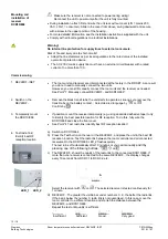
Press the override button

 on the receiver to manually override the relay. LED_1

flashes. Override is active for at least 15 minutes. Press again

 to remove manual

override.
If the room controller sends a control telegram within these 15 minutes, the telegram is
suppressed and executed only after these 15 minutes. This function allows for testing the
unit connected to the receiver.
After expiration of manual override, the RCR10/868 immediately executes every control
telegram received.

In the even of errors (e.g. empty batteries), the room controller no longer sends control
telegrams. Press the override button

 on the receiver to permanently turn on the

connected unit. This function allows you to e.g. run the heating system even if the room
controller is off.
When the room controller resumes operation (e.g. after inserting new batteries), its
control telegrams overwrite manual override. Synchronization takes max. 130 minutes.

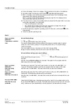
The receiver delivered with REV24RF../SET is connected to the controller at the factory.

Manually connect RCR10/868 and REV24RF.. :

a)

On the RCR10/868 press the “Learn“ button for about 4 seconds: The blue LED_2
flashes slowly, learning mode is active.

b)

Also press the "Learn" button within 20 minutes on the REV24RF.. : The REV24RF..
now either shows confirmation that receiver (RCR 01, RCR02, etc.) is connected or
that connection failed.
Display on the RCR10/868: When connection is successful, the blue LED_2 briefly
flashes quickly, and LED_1 goes from red to green. If connection failed, learning
mode remains active: The blue LED_2 flashes slowly.

c)

You can connect max. 15 receivers to 1 room controller. For unique identification of
each receiver, the REV24RF.. assigns a number to each RCR10/868 connected. The
REV then displays this number after a successful learning process.

·

The error indication

 on the REV24RF.. can point out a radio issue to one of the

connected receivers. Check the error message with

.

Check the receiver as needed.

·

LED_1 is red when the RCR10/868 receives a weak, garbled or no control telegram
for about. 65 minutes. Check the display on the REV24RF.. for an error message.

·

As long as the RCR10/868 correctly receives the control telegrams, the receiver
operates normal. If a control telegram is not received correctly, the relay remains in
the position last switched.
As soon as the RCR10/868 again receives a correct control telegram from the
REV24RF.., the receiver resumes normal operation.

·

The relay switches off, if the RCR10/868 receives no or an incorrect control telegram
from the REV24RF… This switches off the controlled unit. LED_1 is red.
As soon as the RCR10/868 again receives a correct control telegram from the
REV24RF.., the receiver resumes normal operation.

·

  In the case of power interruption at the RCR10/868, the relay goes to OFF.

This is a software class A controller designed for use at a normal degree of pollution.

5.  Finish mounting the
 RCR10/868

6. RCR10/868

Manually override
the relay

7.  Manually connect

REV24RF.. and
RCR10/868

              LED_1   LED_2
LEARN

Notes

Summary of Contents for 24RFDC/SET

Page 1: ...ooling phases Continuous comfort mode Continuous energy saving mode Protection against frost or overheating Exception day 24 hour operation with max 3 heating or cooling phases A separate temperature setpoint can be entered in automatic mode and for the exception day for each heating or cooling phase Heating zone control Possibility to control cooling equipment Advantage for retrofitting renovatin...

Page 2: ...on to radio time signal from Frankfurt Germany REV24RFDC Manual override of the receiving relay Type summary Radio set comprising Room temperature controller REV24RF with 7 day time switch Base and receiver RCR10 868 REV24RF SET Radio set comprising Room temperature controller REV24RFDC with 7 day time switch Receiver for time signal from Frankfurt Germany DCF77 Base and receiver RCR10 868 REV24RF...

Page 3: ...splay Change battery Time of day Alarm Room temperature measured Heating mode Clear text display line max 18 spaces Cooling mode 0 4 8 12 16 20 24 24 hour timeframe with switching pattern with flashing time cursor Weekday max 3 spaces Info Info Weekday block Weekend block Weekday Without language selection Setpoint for comfort mode Setpoint for absence h Time unit Room temperature Absence holiday ...

Page 4: ...plays queued error messages followed by important information e g time switch programs etc 4 Plus button Increase values set time or make a selection 5 Override button party mode In the time switch program this button allows you to quickly change from the active temperature level to the next and back Thus you can quickly change to energy saving temperature when you leave the apartment for a short ...

Page 5: ...ode and exception day time switch programs Start of absence Temperature setpoint during absence End of absence RUN Slider position RUN allows for closing the cover Operating modes The controller offers the two time switch programs and Enter a start time and end time for each comfort phase Also comfort temperature setpoint can be freely entered for each comfort phase Between the comfort phases the ...

Page 6: ...o adapt the switching times and room temperatures only once for each block Switching pattern Blocks You can also enter individual days You can enter the beginning temperature and end of your holidays At the beginning of the holidays the controller switches to the desired holiday temperature and returns to the previously set operating mode at the end of the holidays In holiday mode symbol is displa...

Page 7: ...layed The currently measured temperature flashes Press or to recalibrate by max 5 C Set DIP switch to OFF and press the DIP switch reset button to save the settings The minimum setpoint limitation of 16 C prevents undesired heat transfer to neighboring spaces in buildings featuring several heating zones DIP switch ON Setpoint limitation 16 35 C DIP switch OFF Setpoint limitation 3 35 C factory set...

Page 8: ...nd heat output boiler capacity flow temperature DIP switches 7 ON and 8 ON 1 h C For slow controlled systems DIP switches 7 ON and 8 OFF h C For fast controlled systems DIP switches 7 OFF and 8 ON h C For medium controlled systems DIP switches 7 OFF and 8 OFF OFF Off no effect factory setting Press the DIP switch reset button to save the settings Key for diagram T Temperature C t Forward shift of ...

Page 9: ...N Press and simultaneously for 3 seconds release the buttons and within 3 seconds press and hold down and simultaneously for 3 seconds release and press for another 3 seconds This releases the engineering settings is displayed The display first shows language selection with Code 00 Press the buttons or to navigate the settings Confirm settings by pressing Press the operating mode selector to exit ...

Page 10: ...ttings remain unchanged The clock starts at 12 p m the date on 01 01 08 01 January 2008 During the reset all display fields are lit and can be checked accordingly All user defined settings plus expert settings Press the DIP switch reset button ON 1 3 4 2 2211Z32 5 6 7 8 9 and simultaneously for 5 seconds After the reset all factor settings are reloaded This applies to the program selection slider ...

Page 11: ... room temperature measured Mount the unit base for the REV24RF in the desired location See also Mounting and commissioning notes Attach the base first and then slide the unit in the base from top to bottom You can mount the base on most commercially available recessed conduit boxes or directly on the wall When mounting on a wall make sure there is sufficient clearance above the unit to allow for r...

Page 12: ...tabs on the battery contact Select desired language by or Confirm by If possible mount the receiver temporarily e g using dual sided adhesive tape to try to identify the best possible location for RF reception To do this fully wire the RCR10 868 and close the front cover See Point 4 Test radio link identify best RF reception location a Switch on RCR10 868 b Press the Test button on the rear or the...

Page 13: ... Learn button for about 4 seconds The blue LED_2 flashes slowly learning mode is active b Also press the Learn button within 20 minutes on the REV24RF The REV24RF now either shows confirmation that receiver RCR 01 RCR02 etc is connected or that connection failed Display on the RCR10 868 When connection is successful the blue LED_2 briefly flashes quickly and LED_1 goes from red to green If connect...

Page 14: ...from by flying parts Do not allow the batteries to come into contact with water Do not charge the batteries Do not damage or destroy the batteries Do not heat the batteries to more than 85 C WARNING Electrolyte leakage Chemical burns Only grasp damaged batteries using suitable protective gloves If electrolyte comes into contact with eyes immediately rinse eyes with plenty of water Consult a doctor...

Page 15: ...ed on EU regulation 813 2013 Eco design directive and 811 2013 Labelling directive concerning space heaters combination heaters the following classes apply Application with On Off operation of a heater PMW TPI room thermostat for use with On Off output heaters Class I value 1 Class IV value 2 Degree of protection IP20 Operation Climatic conditions Temperature Humidity 3K3 as per IEC 60721 3 3 5 40...

Page 16: ...r h Storage and transport Climatic conditions Temperature Humidity Mechanical conditions Class 2K3 as per IEC 60721 3 2 25 70 C 93 r h Class 2M2 as per IEC 60721 3 2 Without packaging RCR10 868 REV24RF SET 0 16 kg 0 45 kg Housing front Housing bottom RAL 9003 signal white RAL 7038 gray Housing with base 88 x 114 x 31 5 mm The documents can be downloaded from http siemens com bt download Connection...

Page 17: ... E1 N2 Zone valve Cooling unit Y1 2252S04 M1 N2 T N1 Circulating pump with precontrol by manual mixing valve E1 Cooling unit F1 Thermal reset limit thermostat F2 Manual reset safety limit thermostat M1 Circulating pump N1 Room temperature controller transmitter REV24RF N2 Receiver RCR10 868 N3 Room temperature controller transmitter REV24RF N4 Receiver RCR10 868 Y1 3 port valve with manual adjustm...

Page 18: ...nd Ltd Building Technologies Division International Headquarters Theilerstrasse 1a CH 6300 Zug Tel 41 58 724 2424 Siemens Switzerland Ltd 2008 2018 Technical specifications and availability subject to change without notice www siemens com buildingtechnologies Dimensions Room temperature controller transmitter REV24RF Receiver RCR10 868 ...

Reviews: