background image

Overview 

Siemens Building Technologies, Inc. 


35

ON text  

Text indicating the energized state of a digital point (for example, ON, OPEN, YES). 

override switch  

Button on Room Temperature Sensor that can be pressed by an occupant to change the 
status of a room from night mode to day mode for a predetermined time. 

PID  

Proportional, lntegral, and Derivative. 

RTS  

Room Temperature Sensor. 

Sl units  

Systeme International d'Unites. The international metric system. 

slave mode  

Default application that comes up when power is first applied to a Terminal Equipment 
Controller. 

slope  

Factor that converts analog values (used by the controller) to a form the user can understand 
(engineering units). Slope and intercept constants are determined by the type of field 
input/output represented by the physical or virtual point. 

stand-alone control  

Type of control offered by a controller that is providing independent DDC control to a space. 

Terminal Equipment ControIler  

Siemens Building Technologies product family of equipment controllers (one is the Unit Vent 
Controller — 0 to 10V Output) that house the applications software used to control terminal 
units, such as heat pumps, VAV terminal boxes, fan coil units, unit ventilators, etc. 

Summary of Contents for 125-1957

Page 1: ...Siemens Building Technologies Inc APOGEE Unit Vent Controller 0 to 10V Output Owner s Manual 125 1957 Rev CA July 2007 ...

Page 2: ......

Page 3: ...residential area is likely to cause interference in which case users at their own expense will be required to take whatever measures may be required to correct the interference SERVICE STATEMENT Control devices are combined to make a system Each control device is mechanical in nature and all mechanical components must be regularly serviced to optimize their operation All Siemens Building Technolog...

Page 4: ......

Page 5: ...ay Night Mode 6 Valve Configuration 7 Heating and Cooling Switchover 7 Control Loops 7 Morning Warm up Cool down 8 ON OFF Coil Valve Control 8 Electric Heat 8 Fan Operation 8 Fail safe Operation 8 Application 2281 Heating and or Chilled Water Cooling ASHRAE Cycles I and II 10 Application 2283 Heating and or Chilled Water Cooling ASHRAE Cycle III 13 Application 2284 Heating and DX Cooling ASHRAE Cy...

Page 6: ...0 to 10V Output Owner s Manual ii Point Database 23 Troubleshooting 33 Overview 33 Basic Service Information 33 Ordering Replacement Parts 34 Preventive Maintenance 34 Safety Features 34 Controller LEDs 34 Glossary 35 Overview 35 ...

Page 7: ...Table of Contents iii ...

Page 8: ...ains the following chapters Chapter 1 Product Overview describes the hardware components and accessories used with the controller Chapter 2 Applications describes the control applications available in the controller Chapter 3 Point Database defines the point database descriptors and includes addresses and applications Chapter 4 Troubleshooting describes basic corrective measures to take should you...

Page 9: ...ersonal injury or loss of life may occur to the user if a procedure is not performed as specified Datamate Software Datamate is a customer software tool for all controller communications There are two versions Datamate Base and Datamate Advanced Datamate Base works on an IBM compatible Personal Computer PC or a Handheld PC or Pocket PC running Windows CE Datamate Advanced works only on an IBM comp...

Page 10: ...es Inc Getting Help For more information about the Unit Vent Controller contact your local Siemens Building Technologies representative Where To Send Comments Your feedback is important to us If you have comments about this manual please submit them to SBT_technical editor us sbt siemens com ...

Page 11: ...ovides all termination input output system and local communication connections See Figure 1 The controller hardware consists of the controller with cover and mounting bracket Table 1 Unit Vent Controller 0 to 10 V Output Applications Standard Applications 2281 Heating and or Chilled Water Cooling ASHRAE Cycles l and II 2283 Heating and or Chilled Water Cooling ASHRAE Cycle III 2284 Heating and DX ...

Page 12: ...6 7 8 9 10 11 12 13 14 15 16 17 18 19 20 21 22 23 24 25 26 27 28 CONTROLLER BOARD POWER TRUNK TERMINATIONS TRANSMIT LED RECEIVE LED BST LED LAN TRUNK TERMINATIONS INPUT OUTPUT TERMINATIONS DO LEDS MOUNTING HOLE 2 MOUNTING RAIL ROOM TEMPERATURE SENSOR MMI PORT TEC0197R3 C H S Figure 1 Unit Vent Controller 0 to 10V Output Hardware Inputs Analog Averaging air temperature sensor Room temperature senso...

Page 13: ... 2286 Second stage electric heat 2281 2283 2284 2286 Third stage electric heat 2281 2283 2284 2286 Two position cooling valve actuator 2281 2283 2284 2286 Two position heating valve actuator 2281 2283 2284 2286 DX coil 2284 2286 2287 Power Wiring The controller is powered by 24 Vac and connects to the two screw terminals on the controller Labeled C Common and H Hot on the terminal block labeled 24...

Page 14: ...ociated with it A glowing LED indicates that the DO is energized Receive RX 9 Indicates when flashing that the controller is receiving information from the field panel Transmit TX 10 Indicates when flashing that the controller is transmitting information to the field panel Basic Sanity Test BST 11 Indicates when flashing ON and OFF once per second that the controller is functioning property Some L...

Page 15: ...ent Controller 0 to 10V Output is a 0 to 10V spring return electronic damper motor that positions an outside air damper A 0 to 10V electronic damper motor can be used to position a face and bypass damper Valve Actuators The valve actuators used with the Unit Vent Controller 0 to 10V Output are modulating spring return and non spring return electronic valve motors that position the valves Related E...

Page 16: ...286 Nesbitt Cycle W Application 2287 Slave Mode no control available for set up and point extension device Application 2299 Control Temperature Setpoints The controller maintains a specified temperature setpoint based on Day Night mode the heating cooling mode or the setpoint dial if used Day Night Mode The controller maintains the specified day setpoint temperature during daytime hours and the sp...

Page 17: ...ts a controller in night mode Valve Configuration 2 Pipe Heating Cooling units with one valve controlling a coil that may have hot water or chilled water depending on the season 4 Pipe Heating or Cooling units that are heating or cooling only units with a heating and a cooling coil units with electric heating etc Heating and Cooling Switchover NOTE For 2 pipe heating cooling Application 2281 and 2...

Page 18: ...g warm up or cool down the controller provides maximum heating or cooling with the outdoor air damper closed until the temperature of the space reaches setpoint ON OFF Coil Valve Control When a face bypass configuration is used the coils may be turned on and off with two position valves using DOs Electric Heat If electric heat is used it is controlled as follows HTG OUTPUT Point 60 Stage 1 Stage 2...

Page 19: ... fail safe mode all other DOs can be affected If the discharge air temperature sensor fails the following conditions occur If the last valid value is greater than 150 degrees the heat is turned off the outdoor air damper is closed and the fan is turned on If the sensor does not come back within 10 minutes or if the last valid value is less than 150 degrees the controller shuts down If a failed sen...

Page 20: ...rriding HEAT COOL Point 5 Other features available in this application include morning warm up cool down night mode override free cooling and auxiliary radiation in heating mode NOTE The use of a low temperature detection thermostat LTDT is strongly recommended for hot water and steam systems This application controls room temperature by resetting the discharge air temperature It also controls an ...

Page 21: ...Application 2281 Heating and or Chilled Water Cooling ASHRAE Cycles I and II Siemens Building Technologies Inc 11 Figure 5 Application 2281 Control Drawing Figure 6 Application 2281 Control Drawing ...

Page 22: ...tput Owner s Manual 12 Siemens Building Technologies Inc Figure 7 Application 2281 Control Drawing Figure 8 Application 2281 Control Drawing NOTE The auxiliary radiation is an independent loop and is not sequenced with the other control loops ...

Page 23: ...r features available in this application include morning warm up cool down night mode override free cooling and auxiliary radiation in heating mode NOTE The use of a low temperature detection thermostat LTDT is strongly recommended for hot water and steam systems This application controls room temperature by directly modulating the coil control devices This application also controls an outdoor air...

Page 24: ...APOGEE Unit Vent Controller 0 to 10 V Output Owner s Manual 14 Siemens Building Technologies Inc Figure 10 Application 2283 Control Drawing Figure 11 Application 2283 Control Drawing ...

Page 25: ...Application 2283 Heating and or Chilled Water Cooling ASHRAE Cycle III Siemens Building Technologies Inc 15 Figure 12 Application 2283 Control Drawing Figure 13 Application 2283 Control Drawing ...

Page 26: ...ation include morning warm up cool down night mode override free cooling and auxiliary radiation in heating mode NOTE The use of a low temperature detection thermostat LTDT is strongly recommended for hot water and steam systems While in heating this application controls room temperature by resetting the discharge air temperature While in cooling this application controls room temperature by cycli...

Page 27: ...RAE Cycles I and II Siemens Building Technologies Inc 17 Figure 15 Application 2284 Control Drawing Figure 16 Application 2284 Control Drawing NOTE The auxiliary radiation is an independent loop and is not sequenced with the other control loops ...

Page 28: ...ilable in this application include morning warm up cool down night mode override free cooling and auxiliary radiation in heating mode NOTE The use of a low temperature detection thermostat LTDT is strongly recommended for hot water and steam systems This application controls room temperature by directly modulating the coil control devices This application also controls an outdoor air damper accord...

Page 29: ...Application 2286 Heating and DX Cooling ASHRAE Cycle III Siemens Building Technologies Inc 19 Figure 18 Application 2286 Control Drawing Figure 19 Application 2286 Control Drawing ...

Page 30: ...ng only units can also be controlled with this application by overriding HEAT COOL Point 5 to HEAT Other features available in this application include morning warm up cool down night mode override and free cooling NOTE The use of a low temperature detection thermostat LTDT is strongly recommended for hot water and steam systems This application controls room temperature by directly modulating the...

Page 31: ...Application 2287 Heating and Cooling Nesbitt Cycle W Siemens Building Technologies Inc 21 Figure 21 Application 2287 Control Drawing Figure 22 Application 2287 Control Drawing ...

Page 32: ...pplication that comes up when power is first applied to the controller Slave mode provides no control Its purpose is to allow the operator to perform equipment checkout before a control application is put into effect and to set some basic controller parameters CTLR ADDRESS APPLICATION etc NOTE Slave mode provides no control The input labeled DI3 AI3 on the controller can be used either as a DI poi...

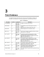
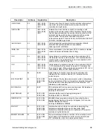
Page 33: ... 2287 The temperature setpoint in degrees that the controller maintains during day periods in cooling mode if a room temperature sensor setpoint dial is not present or is not used Refer to STPT DIAL Point 14 Valid entry range 48 to 95 F 9 35 C DAY HTG STPT 07 2281 2283 2284 2286 2287 The temperature setpoint in degrees that the controller maintains during day periods in heating mode if a room temp...

Page 34: ...r NO AUX TEMP 15 2299 Actual reading from a 100K ohm thermistor connected to the controller s Al 3 input When a thermistor is connected at Al 3 DI 3 is not available Refer to Dl 3 Point 25 DISCH TEMP 15 2281 2284 2287 Actual reading from a 100K ohm thermistor connected to the controller s AI 3 input When a thermistor is connected at Al 3 DI 3 is not available Refer to DI 3 Point 25 MA TEMP 15 2283...

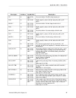
Page 35: ...ntact connected to the controller at Al 3 Dl 3 ON indicates that the contact is closed OFF indicates that the contact is open When a contact is connected at DI 3 Al 3 is not available Refer to AUX TEMP Point15 DI 4 26 2299 Actual status of a contact connected to the controller ON indicates that the contact is closed OFF indicates that the contact is open LOW TEMP DET 26 2281 2283 2284 2286 2287 Ac...

Page 36: ...d of the voltage range where the actuator controlled by AO3 moves AO DIR REV 37 2281 2283 2284 2286 2287 Masking point used to determine NO NC status of actuators attached to analog outputs AOV1 38 2281 2283 2284 2286 2287 2299 Displays the voltage signal to AO1 AOV2 39 2281 2283 2284 2286 2287 2299 Displays the voltage signal to AO2 AOV3 40 2281 2283 2284 2286 2287 2299 Displays the voltage signa...

Page 37: ...pen in night mode in both heating and cooling modes recommended for systems with hot water NO indicates heating valve will be controlled normally Valid input YES or NO NGT CLG MODE 54 2281 2283 2284 2286 2287 YES indicates that night cooling is available NO indicates that night cooling is not available Valid input YES or NO AUX OUTPUT 55 2281 2283 2284 2286 Indicates the percentage of time the aux...

Page 38: ...2284 2286 2287 The proportional gain value for the heating temperature control loop HTG l GAIN 68 2281 2283 2284 2286 2287 The integral gain value for the heating temperature control loop HTG D GAIN 69 2281 2283 2284 2286 2287 The derivative gain value for the heating temperature control loop HTG BIAS 70 2281 2283 2284 2286 2287 The biasing of the heating temperature control loop Refer to HTG LOOP...

Page 39: ... 2283 2286 The integral gain value for the mixed air control loop OA l GAIN 82 2287 The integral gain value for the outdoor air damper control loop AUX D GAIN 83 2281 2284 The derivative gain value for the auxiliary control loop MA D GAIN 83 2283 2286 The derivative gain value for the mixed air control loop OA D GAIN 83 2287 The derivative gain value for the outdoor air damper control loop AUX BIA...

Page 40: ...L STPT Point 92 The difference exceeding this value is one of the conditions necessary to change modes between heating and cooling Valid input 0 to 255 F AUX DSH STPT 91 2281 2284 The setpoint of the auxiliary radiation control loop CTL STPT 92 2281 2283 2284 2286 2287 The actual setpoint value being used as input for the active temperature control loop DISCH STPT 93 2281 2284 2287 The setpoint of...

Page 41: ...ays remove power to the controller when installing or replacing it Since the controller does not have a power switch the recommended method of removing power to a locally powered controller is to turn OFF the power to the 24 Vac transformer The recommended method of removing power to a controller on a power cable even to service a single controller is to turn OFF the power at the transformer NOTE ...

Page 42: ... dirty environments may require periodic cleaning to function properly Safety Features The controller board stores the controller s address applications and point values In the event of a power failure or a reset these values are retrieved from the controller s permanent memory and are used by the controller unless overridden by a field panel If one of the following conditions occurs the controlle...

Page 43: ...Technologies representative Al Analog Input Physical point which accepts a continuous variable signal algorithm Mathematical formula used to calculate an output value using varying inputs AO Analog Output Physical point that generates a continuous variable signal centralized control Type of control offered by a controller that is connected by means of a Floor Level Network FLN with an APOGEE field...

Page 44: ... centralized control of system components and equipment controllers A field panel samples and processes field data initiates control actions communicates with its operators and generates reports displays and warnings FLN Field Level Network intercept Factor which converts analog values used by the controller to a form which the user can understand engineering units Slope and intercept constants ar...

Page 45: ...er is first applied to a Terminal Equipment Controller slope Factor that converts analog values used by the controller to a form the user can understand engineering units Slope and intercept constants are determined by the type of field input output represented by the physical or virtual point stand alone control Type of control offered by a controller that is providing independent DDC control to ...

Page 46: ... Owner s Manual Siemens Building Technologies Inc 36 unbundle Term used to describe the entering of a point that resides in a controller s database into the field panel s database so that it can be monitored at or controlled from the field panel ...

Page 47: ... cooling switchover 7 night mode override switch 7 B Basic Sanity Test BST 32 basic service information 31 BST LED 32 C centralized control 33 communication wiring 3 4 control loop 33 controller LEDs LED indicators 4 32 controller hardware 1 D damper actuator 5 database see point database Datamate Software v DDC see Direct Digital Control DI see digital input digital input 2 33 digital output 3 34...

Page 48: ... maintenance 32 R related equipment 5 replacement parts 32 Room Temperature Sensor 4 RTS see Room Temperature Sensor RX LED 32 S safety features 32 service information basic 31 SI units 35 slave mode 35 slope 35 stand alone control 35 static discharge 31 T TEC see Terminal Equipment Controller temperature sensor 4 discharge air 5 mixed air 5 room 4 temperature sensors 4 mixed air 5 room 4 Terminal...

Reviews: