background image


IV420E Rev.00 SIEL S.p.A. 


Installation and user manual 

Date of issue: 2019-01-29   


                                  Pag. 15 di 72+ FR 


CAUTION!


Protective earth cable: Connect each cabinet to the main ground 
system. For Grounding connection, follow the shortest route 
possible. 

WARNING! 

Failure  to  follow  adequate  earthing  procedures  may  result  in 
electromagnetic  interference  or  in  hazards  involving  electric  shock 
and fire 
 

3.7 Power cable connect


Once  the  equipment  has  been  finally  positioned  and  secured,  connect  the  power  cables  as 

described in the following procedure. 

Verify the UPS is totally isolated from its external power source and also all power isolators of the 

UPS are open. Check to see if they are electrically isolated, and post any necessary warning signs to 

prevent their inadvertent operation. 

Open the UPS rear panel; Remove the cover of terminals for wiring easily. 

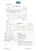
3.7.1 Common input connection 

50kVA&60kVA 


Summary of Contents for 50-200kVA PF-1 UPS

Page 1: ...ev 00 SIEL S p A Installation and user manual Date of issue 2019 01 29 Pag 0 di 52 FR 50 200kVA PF 1 UPS INSTALLATION AND USER MANUAL SAFEPOWER S KEEP FOR FUTURE REFERENCE for the entire life of the a...

Page 2: ......

Page 3: ...is an intelligent three phase in Three phase out high frequency online UPS designed by our R D team who is with years of designing experiences on UPS With excellent electrical performance perfect inte...

Page 4: ...r cable connect 15 3 8 Battery connection 19 3 9 UPS parallel Installation 20 3 10 LBS installation 21 3 11 Computer access 22 4 Operation 24 4 1 Operation Modes 24 4 2 Turn on off UPS 26 4 3 The LCD...

Page 5: ...arth the UPS before starting it 3 Don t open or damage battery for the liquid spilled from the battery is strongly poisonous and do harmful to body 4 Please avoid short circuit between anode and catho...

Page 6: ...ystem of which input current is kept in balance No unbalance problem might occur Digital Control This series UPS is controlled by Digital Signal Processor DSP enhance it increases reliability performa...

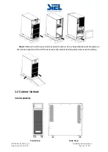
Page 7: ...ation 3 1 Unpacking and checking Don t lean the UPS when moving it out from the packaging Procedure Step 1 Use a pallet truck to transport the UPS to the installation position Step 2 Check the UPS pac...

Page 8: ...019 01 29 Pag 6 di 72 FR Step 8 Remove the front panel and real panel to remove the L shaped bracket and the plates at the left and right side of the UPS that secures the cabinet and the pallet and se...

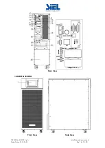
Page 9: ...IV420E Rev 00 SIEL S p A Installation and user manual Date of issue 2019 01 29 Pag 7 di 72 FR Rear View 100kVA 120kVA Front View Side View...

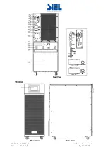
Page 10: ...IV420E Rev 00 SIEL S p A Installation and user manual Date of issue 2019 01 29 Pag 8 di 72 FR Rear View 160kVA Front View Side View...

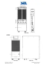
Page 11: ...IV420E Rev 00 SIEL S p A Installation and user manual Date of issue 2019 01 29 Pag 9 di 72 FR Rear View 200kVA Front View Side View...

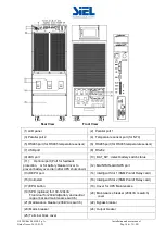
Page 12: ...ort Port for feedback protection or for battery breaker driver to prevent battery over drain after UPS shuts down 12 MAINTAIN AUXSWS port 13 REPO port 14 Intelligent Slot 1 SNMP card Relay card 15 Col...

Page 13: ...e installed unless the internal and external of the equipment is fully dry Otherwise there will be in danger of electric shock Batteries should be mounted in an environment where the temperature is wi...

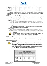
Page 14: ...tion shall be fitted with protective devices that may avoid the risk of UPS overloaded Over current Protection device shall be installed at the distribution panel of the incoming main supply It may id...

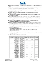
Page 15: ...s input and bypass input share a power source configure both types of input power cables as mains input power cables The cables listed in Table are used only when the following requirements are met Ro...

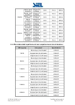
Page 16: ...mped OT terminals M10 11mm 26N m 3 6 3 Recommended input front end and output back end circuit breakers UPS capacity Component Specifications 50kVA Mains input circuit breaker 100A 3P Bypass input cir...

Page 17: ...zards involving electric shock and fire 3 7 Power cable connect Once the equipment has been finally positioned and secured connect the power cables as described in the following procedure Verify the U...

Page 18: ...se L1 Vin L1 Primary input Phase L1 Vout L2 Output Phase L2 Vin L2 Primary input Phase L2 Vout L3 Output Phase L3 Vin L3 Primary input Phase L3 Vout N Output Neutral Vin N Input Neutral for primary an...

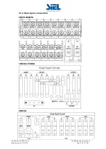
Page 19: ...IV420E Rev 00 SIEL S p A Installation and user manual Date of issue 2019 01 29 Pag 17 di 72 FR 3 7 2 Dual input connection 50kVA 60kVA 100kVA 160kVA 200kVA...

Page 20: ...Dual input operation make sure the copper wire between each input lines have been removed The AC input and the AC bypass supplies must be referenced to the same neutral point Choose appropriate power...

Page 21: ...positive battery the BAT N is connected to the cathode of the positive battery and the anode of the negative battery the BAT is connected to the cathode of the negative battery factory setting of the...

Page 22: ...each UPS input breaker is in off position and there is no any output from each UPS connected Battery groups can be connected separately or in parallel which means the system itself provides both sepa...

Page 23: ...rce 2 The outputs of all the UPS must be connected to a common output bus 3 The length and specification of power cables including the bypass input cables and the UPS output cables should be the same...

Page 24: ...UPS_1 UPS_2 UPS_M Input Output STS MASTER SLAVE Load M N 1 3 11 Computer access One end of a USB cable connect to the computer the other end connect to the USB port on the UPS Open the software Muser...

Page 25: ...Append then goes to a window of Append equipment Put the UPS name into Equipment Name and UPS ID address into Equipment address Click the button Append then the connection between UPS computer is acco...

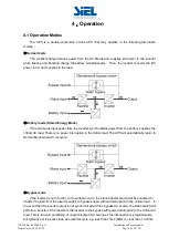
Page 26: ...supplies the critical AC load There is no power interruption to the critical load The UPS will automatically return to Normal Mode when AC recovers Bypass mode If the inverter is out of order or if o...

Page 27: ...de the UPS works at Line interactive mode so the UPS will transfer to bypass supply When the AC is out of set window the UPS will transfer from bypass to Inverter and supplies power from the battery a...

Page 28: ...ypass mode to inverter mode then the bypass LED extinguishes and the inverter LED lights up No matter whether the UPS can work normally or not all the status will be shown on the LCD display 4 2 2 Tes...

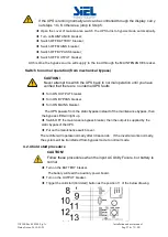
Page 29: ...ion until you have verified that there are no internal UPS faults Turn ON OUTPUT breaker Turn ON BYPASS breaker Turn ON MAINS breaker The UPS powers from the static bypass instead of the maintenance b...

Page 30: ...door to easily access to the main power switch Switch OFF the MAINS breaker Switch OFF the BYPASS breaker Open the OUTPUT breaker The UPS shuts down To completely isolate the UPS from AC Mains all in...

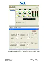
Page 31: ...anual Date of issue 2019 01 29 Pag 29 di 72 FR Click Set at User Set window At the window of Data Set click Work Mode choose Parallel for the value then click Set as shown in below picture If the UPS...

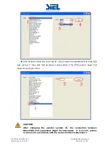
Page 32: ...for the parallel UPS ID at the right side such as 1 then click Set as shown in below picture If the UPS sounds a beep that means the setting is correct CAUTION After changing the parallel system ID th...

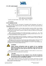
Page 33: ...UPS Connect all the UPS according to parallel cable installation and then power on the UPS 4 3 The LCD Display LCD control panel introduction 1 LED from top to bottom Fault bypass battery inverter 2...

Page 34: ...flow state of UPS work and quickly enters real time data by clicking on the block 4 3 2 Status View the voltage and current of the main bypass output battery can also be entered through by real time d...

Page 35: ...ck the main block to enter the main data display window click return to return to the previous window click home page to return to the main page 4 3 2 2 Bypass Click the bypass block to enter the bypa...

Page 36: ...lation and user manual Date of issue 2019 01 29 Pag 34 di 72 FR 4 3 2 3 Output Click the output block to enter the output data display window click return to return to the previous window click home p...

Page 37: ...ation and user manual Date of issue 2019 01 29 Pag 35 di 72 FR 4 3 2 4 Battery Click the battery block to enter the battery data display window click return to return to the previous window click home...

Page 38: ...01 29 Pag 36 di 72 FR 4 3 3 Alarm View the alarm and history of the UPS and open or close the buzzer 4 3 3 1 Curr Alarm Click the curr alarm to enter the current alarm display window click return to...

Page 39: ...w click return to return to the previous window click home page to return to the main page 4 3 3 1 Buzzer Click the buzzer mute then the buzzer will mute and the red block will change to green if the...

Page 40: ...user manual Date of issue 2019 01 29 Pag 38 di 72 FR 4 3 4 Setting There are two levels the basic setting for user settings advanced setting for technical personnel please contact the relevant techni...

Page 41: ...IV420E Rev 00 SIEL S p A Installation and user manual Date of issue 2019 01 29 Pag 39 di 72 FR 4 3 4 1 Basic Setting Click basic setting enter by input the correct password The user password is 111111...

Page 42: ...ome page to return to the main page 4 3 4 1 2 Password Click password block enter user password setting page input old password and new password then click save confirm to save the change Password for...

Page 43: ...Brightness Click the text to input new value and click the save config block to save Value range is 1 63 default value is 63 Click return to return to the previous window click home page to return to...

Page 44: ...dow click home page to return to the main page Date format has 3 formats Date current date Time current time 4 3 4 1 5 Communication setting Click the text to select other value or input new value and...

Page 45: ...s that the bypass voltage is not normal and that the bypass is unavailable NOTE When the voltage level is 380 V the value range is 10 15 20 and 25 default When the voltage level is 400 V the value ran...

Page 46: ...IV420E Rev 00 SIEL S p A Installation and user manual Date of issue 2019 01 29 Pag 44 di 72 FR...

Page 47: ...to save Click return to return to the previous window click home page to return to the main page Working Mode Select the work mode of UPS work mode Single mode Parallel mode ECO mode Auto Turn on Sel...

Page 48: ...LBS master LBS slave Default is LBS disable Bypass rate tracking rate Inverter frequency tracking to bypass frequency rate The value range is 0 5 2 and is 1 by default SCR Over Temp Power Supply Speci...

Page 49: ...system This parameter specifies the number of transfers between bypass mode and normal mode within 1 hour which ensures system security The value can be 3 to 10 and is 10 by default Temp Sensor Switch...

Page 50: ...arallel mode The value can be 1 6 default value is 1 Cabinet Paral Basic Units Parallel cabinet number must modify the total parallel cabinet number after set work mode to parallel mode The value can...

Page 51: ...V 230V 240V Output Ivn Volt Regu Inverter voltage regulated the value can be 5 0 5 step is 0 5 default value 0 4 3 4 2 4 Battery setting Battery Group Must modify the number to actual configuration th...

Page 52: ...attery capacity The value can be 0 05 0 15 and is 0 1 by default Cell float voltage The float voltage value can be 2 23 2 30 V cell and is 2 25 V cell by default Cell boost voltage The battery equaliz...

Page 53: ...be 1 60 1 90 and is 1 80 by default Float Temp Compen Coeff modify the voltage of compensation after enable the switch the value can be 0 001 0 007 cell and is 0 003 by default Boost Charge Setting B...

Page 54: ...on The default value is Disable Battery abnormal BCB trip Enable or disable BCB trip single output The default value is Disable Bypass Feedback Enable or disable bypass feedback output The default val...

Page 55: ...IV420E Rev 00 SIEL S p A Installation and user manual Date of issue 2019 01 29 Pag 53 di 72 FR 4 3 5 1 USB Wizard History Output download history and setting record by USB 4 3 5 1 1 Alarm Log Output...

Page 56: ...p A Installation and user manual Date of issue 2019 01 29 Pag 54 di 72 FR 4 3 5 1 2 Setting Log Output 4 3 5 2 Battery Self Check can select check by Timing Daily Timing Weekly The default value is Ti...

Page 57: ...on and user manual Date of issue 2019 01 29 Pag 55 di 72 FR 4 3 5 2 1 Timing Daily modify the check date time and check time 10S default 10min EOD 4 3 5 2 2 Timing Weekly modify the check date time an...

Page 58: ...issue 2019 01 29 Pag 56 di 72 FR 4 3 6 Common INV ON OFF Battery test and Fault clear 4 3 6 1 INV ON OFF Single OFF Inverter OFF location UPS Single ON Inverter ON location UPS Parallel OFF Inverter O...

Page 59: ...manual Date of issue 2019 01 29 Pag 57 di 72 FR 4 3 6 2 Battery Test 10S battery test for 10s 10min battery test for 10min EOD battery test to EOD 10 battery test down 10 capability 4 3 6 3 Fault cle...

Page 60: ...and for LED Fault Bypass Battery Inverter 1 Initialized EXTINGUISH EXTINGUISH EXTINGUISH EXTINGUISH 2 Standby Mode EXTINGUISH EXTINGUISH X EXTINGUISH 3 No Output EXTINGUISH EXTINGUISH X EXTINGUISH 4 B...

Page 61: ...it 21 04A Inverter relay Broken Beep continuously Fault LED lit 22 04D INV par cable Fault Twice per second Fault LED lit 23 051 Output Short Circuit Once per second Fault LED blinking 24 054 INV Comm...

Page 62: ...Once per 2 seconds BYPASS LED blinking 20 142 Unit quantity mismatch Once per 2 seconds FAULT LED blinking 21 143 Parallel Overload Once per 2 seconds INVERTER LED blinking 22 144 Bypass Overload Onc...

Page 63: ...gy of the UPS Network Management Relay card A 10 pin terminal is supported to offer the signals of Bypass Utility Failure Inverter On Battery Low UPS fault UPS Alarm and UPS Shutdown for HIPOWER serie...

Page 64: ...2 Battery Mode 50 60 1 0 02 Hz Crest factor 3 1 Harmonic distortion THD 2 with linear load 4 with non linear load Efficiency 95 5 BATTERY Battery voltage Optional Voltage 180V 192V 204V 216V 228V 240...

Page 65: ...de 1500m When 1500m lower the rated power for use Noise level 58dB 60dB 62dB 63dB 66dB 68dB PHYSICAL Dimension D W H mm 828x250x868 850x442x1100 850x442x1200 Net weight kg 80 83 147 155 190 230 STANDA...

Page 66: ...s not indicate any failure but output do not have voltage Output cable does not well connected Output breaker do not switch on Make sure the output cable is well connected Switch on the output breaker...

Page 67: ...scription Pin 1 Pin 1 PC 5V Pin 2 Pin 2 PC DPLUS signal Pin 3 Pin 3 PC DMINUS signal Pin 4 Pin 4 Signal ground Available function of USB Monitor UPS power status Monitor UPS alarm info Monitor UPS run...

Page 68: ...UPS RS232 port Pin 2 Pin 2 UPS send PC receive Pin 3 Pin 3 PC send UPS receive Pin 5 Pin 5 ground Available function of RS232 Monitor UPS power status Monitor UPS alarm info Monitor UPS running param...

Page 69: ...escription Pin 1 5 Pin 1 5 485 A Pin 2 4 Pin 2 4 485 B Pin7 Pin7 12Vdc Pin8 Pin8 GND Available function of RS485 Monitor UPS power status Monitor UPS alarm info Monitor UPS running parameters Timing o...

Page 70: ...efinition of Male port Instruction Relay Dry Contact Port 5A 277Vac UPS Instruction Pin1 Normally NC Pin2 Normally NO Pin3 Pin4 Common Function 1 description default internal J6 jumper Drive the bypas...

Page 71: ...n Definition of port Connection diagram Connection between the button and UPS REPO port Button UPS REPO Description Pin 1 Pin 1 EPO NO Pin 2 Pin 2 EPO 12V Pin 1 Pin 3 EPO NC Pin 2 Pin 4 EPO 12V A remo...

Page 72: ...ins configurations via the output port as per Appendix 6 If the contactor coil exceeds the voltage current limits of the UPS output port a 24 Vcc source should be generated from the same source the co...

Page 73: ...Route the cable with the other signal cables 2 Connect the UPS backfeed dry contact port 4 to the contactor C coil Route the cable with the other signal cables 3 Connect the fuse F and the coil of C...

Page 74: ......
Reviews: