Installation and operating instructions
AEROMAT 100
03.2020
9
Accessories
Please indicate the desired lengths for all accessory items (see order form AEROMAT 100).
Designation
Material no.
Use
Flush switch AF1, single, white
128032
Type DK
Surface-mounted casing for switch AF1, white
149027
Rod operating device, white (RAL 9016)
aer.gestaenge
Type D
Rod operating device, silver (EV 1)
Aluminium profile 20 x 20 x 2 mm, white (RAL 9016)
aer.winkel 20x20x2
Type D and DK
Aluminium profile 20 x 20 x 2 mm, silver (EV 1)
Stop profile, white (RAL 9016)
aer.anschlagprofil
Type D and DK
Stop profile, silver (EV 1)
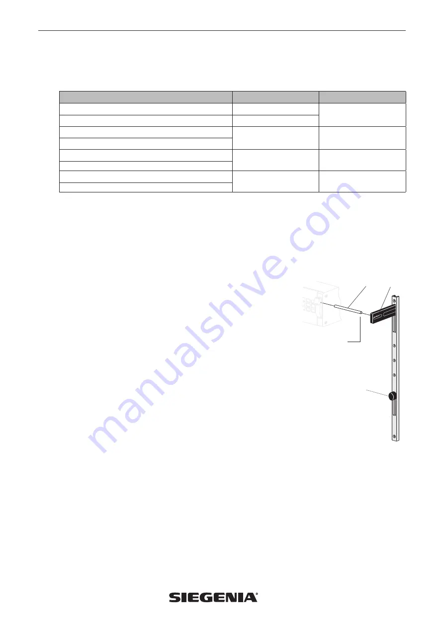
Rod operating device (optional)
The ventilator is operated used a sliding button (
a
) on the rod. You can slide the button up or down manually. The sliding
button’s "Open" and "Close" positions (or intermediate positions) correspond to the position of the operating lever on the unit.
The rod is mounted on the same door or window element in which the ventilator is mounted. If the ventilator is mounted in a
moveable window sash, for example, it is essential to also attach the rod to the same sash profile.
Assembling the rod in three steps
Note:
Depending on the assembly situation, the pin (
b
) and the clip (
c
)
must be shortened.
1. Insert pin
- Open the fan flap of the AEROMAT 100, thus moving the operating lever into
the upper position. Insert the provided pin (
b
) in the intended bore hole in the
operating lever of the AEROMAT 100.
2. Adjust the rod
- The sliding button (
a
) of the rod must be in the upper position ("Open").
- Insert the front groove of the clip (
c
) into the pin (
b
) that is fixed above the
AEROMAT 100. Push the rod against the existing profile and hold the rod with
one hand.
- Now move the sliding button (
a
) from "Open" to "Close" and adjust the rod in
such way that the fan flap closes and opens completely.
3. Secure the rod
- Directly screw the rod with wooden or self-tapping countersunk screws (provided
on-site) into the existing screw holes in the adjusted position. The screw holes
have the following dimensions:
Ø screw hole = 3.7 mm
Ø counterbore = 7.2 mm
ø 5 mm
a
b
c
Summary of Contents for AERO
Page 11: ......


