20
4526
8
2020
-
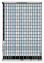
SE IP 50
MG_0035
A2
A
1
Fu
se
re
d
gr
ey
bl
ue
bl
ac
k
gr
ey
bl
ue
br
own
re
d
6 1
23
2i
El
ect
ro
ni
c
con
tr
ol b
ox
Th
er
m
al
swi
tc
h
Ba
tt
er
y
12
V
or
24
V
Ba
tt
er
y
m
ai
n
sw
itc
h
M
4
3 2 1
3
4
2
1
8
6
9
5
re
d
re
d
bl
ac
k
7
whi
te
NB!
Make sure to not use
any electronic interface
box (delay box) older than
the 6 1232i (ex. 6 122x)
on SP75Ti, SP95Ti, and
SP125Ti.
NB!
Make sure to not use
any electronic interface
box (delay box) older than
the 6 1232i (ex. 6 122x)
NB! Very important to check the following with main-switch
position:
After all electrical connections have been completed check with an
ohm meter that there is no electrical connection between electro-
motor body and positive terminal on the motor and between the
electro motor body and the negative (A1) terminal on the motor.
If you feel unsure on how to perform this check, contact skilled
personnel for guidance.
Control Panel Cable Installation
EN
• All Sidepower control panels can be used in any combination.
• All control panels can be installed using:
• Y-connectors - for standard on/off
• T-connectors - for S-link proportional power system.
(NB: If two or more control panels are operated at the same time in opposite directions, the electronic control box will stop the thruster until
it receives a single signal or thrust in one direction.)
•
Sidepower on/off equipment it is entirely “plug & play” and require no additional confi guration setup.
See the Control panel manual for more information.
MC_0041
!
Please refer to the graphic for special considerations relating to your model
!
MG_0025
Thruster
Motor
Connect round end
of control adapter
1
2
3
4
2
1
3
4
Pin 4
Pin 3
Pin 2
Pin 4
Pin 3
Pin 2


