background image

SYSTEM DESCRIPTION   


45 

8023994-17I6/2020-03-19|SICK 

Subject to change without notice 

O R I G I N A L   O P E R A T I N G   I N S T R U C T I O N S | VMS4100/5100 

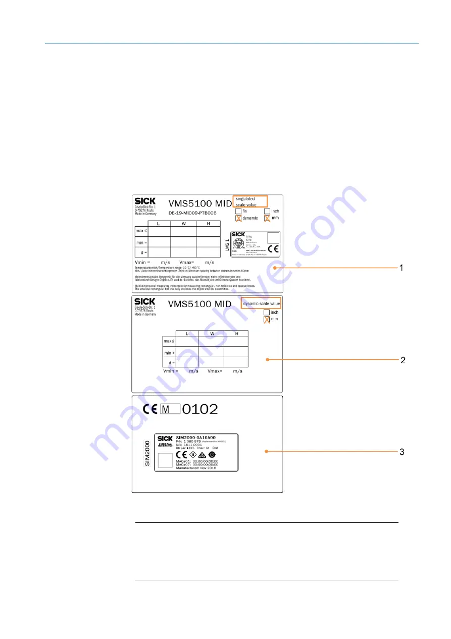
For dynamic scale value switchover, the scale values for two scale interval values used 
must be described in two separate information labels and attached to the system 
indelibly.  
For scale interval value 1, use the information label for the relevant operating mode 
(

Singulated

 or 

Touching/Side-by-Side

). The 

dynamic

 scale value and the measuring unit 

(

mm

 or 

inch

) with the accompanying dimensional values must be specified on the 

appropriate information label in indelible ink. The LMS4xxx type label must also be affixed 
to this information label.  
On the information label for scale interval value 2, the measuring unit (

mm

 or 

inch

with the accompanying dimensional values must be specified. 
The type label for the SIM2000 system controller must be affixed to the metrology 
information label in the appropriate field.  


Fig. 39:  MID - information labels for the VMS5100 in “Singulated” operating mode with dynamic 

scale value switchover and affixed type labels 


Legend 

Identification label for scale interval value 1  

(for “Singulated” operating mode) 

Identification label for scale interval value 2 

Metrology information label with affixed type label 

Information labels with 

dynamic scale value 

switchover 

Summary of Contents for VMS4100

Page 1: ...O P E R AT I N G I N S T R U C T I O N S VMS4100 5100 Track and trace systems ...

Page 2: ...d by copyright The associated rights are reserved by SICK AG Reproduction of this document or parts of this document is only permissible within the limits of the legal provisions of copyright law Any modification abridgment or translation of this document is prohibited without the express written permission of SICK AG The trademarks mentioned in this document are the property of their respective o...

Page 3: ...17 3 2 3 Photoelectric retro reflective sensor trigger optional 17 3 2 4 Cabinet 18 3 2 5 Expanding the system with a reading station 20 3 3 Triggering the recording of measured values 21 3 4 Operating modes 23 3 4 1 Singulated operating mode cubic only 23 3 4 2 Singulated operating mode with additional Touching Side by Side Singulation verification SIV function 24 3 4 3 Touching Side by Side oper...

Page 4: ...FT display set up at the factory 80 5 5 1 Cabinet without Ethernet switch 80 5 5 2 Cabinet with Ethernet switch 81 5 6 Connecting the incremental encoder 82 5 7 Connection for the photoelectric retro reflective sensor trigger optional 83 5 8 Connection for the customer interface 84 6 Commissioning 85 6 1 Switching on the system 85 6 2 Configuring the system with SOPAS 86 6 2 1 Connecting the confi...

Page 5: ... 109 8 1 3 Fault indication on the photoelectric retro reflective sensor trigger 110 8 2 Checks on the SIM2000 111 8 2 1 Checking the triggering 111 8 2 2 Checking the incremental encoder 112 8 2 3 Checking the CAN cabling 113 8 3 Detailed fault analysis 114 9 Technical data 115 9 1 Data sheet 115 9 2 Dimensional drawings 117 9 2 1 Dimensional drawings for the 2D LiDAR sensor 117 9 2 2 Dimensional...

Page 6: ...sembling the data and information contained in this document The manufacturer accepts no liability for damage caused by Failure to observe this document Non compliance with notes and regulations Unauthorized mounting and installation Unauthorized technical and other changes Use of unauthorized spare parts wear and tear parts and accessories Unauthorized changes adjustments and or manipulations of ...

Page 7: ...sonnel 1 5 Other relevant technical documentation information Technical system documentation E231167 A EPLAN without Ethernet switch E264713 A EPLAN with Ethernet switch Technical data Connection diagram Terminal diagram Operating instructions for the following system components Component Manufacturer LMS4000 2D LiDAR sensor operating instructions SICK SIM2000ST Sensor Integration Machine operatin...

Page 8: ...the additional Singulation verification SIV function Here the objects located in the measuring range are quantified If there are several objects in the measuring range the number of detected objects is determined Dimensional values are labeled as NON LFT but can be outputted If the next object is singular it will then once again be normally dimensioned in Singulated mode In the Touching Side by Si...

Page 9: ...onal measurement system System damage transport damage Damage to the individual components can lead to malfunctions of the system as a whole Do not ignore any damage caused to system components during transport In case of damage contact SICK Service 2 3 Requirements for the qualification of personnel Only qualified persons with the relevant technical expertise are permitted to work on the system Q...

Page 10: ...e Ground and short circuit Cover or enclose live parts in the vicinity Never enter the area under suspended loads Pay close attention when lifting loads Comply with lifting instructions to prevent injuries and accidents Use suitable undamaged lifting tools Wear personal protective equipment safety helmet safety shoes 2 5 Protective devices The multi dimensional measurement system is designed in a ...

Page 11: ...annot provide any warranty or accept any liability whatsoever for such use 2 8 Safety conventions The warnings used in this manual have the following meanings DANGER Identifies an imminent danger which will lead to death or serious injuries if not prevented WARNING Identifies a situation presenting danger which will lead to death or serious injuries if not prevented CAUTION Identifies a situation ...

Page 12: ...em components Warning labels must not be removed or covered up If labels are missing these must be affixed Damaged labels must be replaced Symbol Meaning Hazardous point warning Hazardous electrical voltage warning Laser beam warning Suspended load warning 2 10 Mandatory symbols Symbol Meaning Read document Use head protection Use foot protection Disconnect before maintenance or repairs ...

Page 13: ... with laser protective cover VMS4100 or 1 LMS4521R 16000 2D LiDAR sensor with laser protective cover VMS5100 MID 1 LFT display VMS5100 MID only 1 SIC2000 cabinet with SIM2000 system controller and power supply module s 1 Incremental encoder e g DFV60 with mounting kit 1 Mounting bracket for mounting the LMS4x21 2 beam blockers Connecting cables Optional 1 Photoelectric retro reflective sensor for ...

Page 14: ...LFT display VMS5100 only 3 DFV60 incremental encoder 4 Photoelectric retro reflective sensor for triggered systems e g RAY26 5 Cabinet with the SIM2000 system controller and power supply units Mount the system components according to the technical drawing on a frame provided by the customer Additional glare protection on the frame beam blocker prevents objects located outside of the measuring rang...

Page 15: ...ensor The resulting extension of the light path makes it possible to save space when mounting the 2D LiDAR sensor on the conveying equipment The mirror s special vacuum coated surface eliminates refraction meaning that no loss occurs during deflection The figure above shows an example of how the 2D LiDAR sensor and deflector mirror can be arranged above the transport belt The remaining system cons...

Page 16: ... systems approved for billing applications Consists of an LMS4x21 2D LiDAR sensor with laser protective cover with the sensor mounted in a centered position on a profile above the conveying equipment Used to determine the relevant object dimensions through non contact detection of objects on flat conveying systems VMS5100 measurement systems operated in legal for trade applications also have a sep...

Page 17: ...ce of the conveyor belt using a precision measuring wheel 3 2 3 Photoelectric retro reflective sensor trigger optional Fig 5 Photoelectric retro reflective sensor trigger and reflector Legend 1 Photoelectric retro reflective sensor e g RAY26 2 Reflector The light band emitted by the object detection photoelectric sensor is reflected back by a reflector Sender and receiver are arranged parallel to ...

Page 18: ...m components Contains the SIM2000 system controller the central processing and control unit of the VMS4100 5100 The SIM2000 system controller contains the legally relevant memory alibi memory Central power supply for all system components Coordinates all connected sensors and processes the measured values received The SIM2000 system controller receives the measuring points from the 2D LiDAR sensor...

Page 19: ...tage to the LFT display 4 Terminals for voltage supply IN 100 264 V AC 50 60 Hz 5 Air outlet for cooling with filter mat 6 Power supply unit for supplying voltage to the SIM2000 and 2D LiDAR sensors 7 Terminals 24 V DC and fuse module OUT 8 Ethernet switch for connecting the system components The cabinet also contains an Ethernet switch for connecting system components A manipulation protective pl...

Page 20: ...plication specific trigger elements and or a combination of these components in any desired arrangement Allows automated object identification using bar codes Streamlines process automation NOTE The multi dimensional measurement system can also supply the focus information for the connected camera systems The devices are connected to the multi dimensional measurement system via the CAN bus of the ...

Page 21: ...e recording of measured values Fig 9 Free running mode Legend 1 Measurement site 2 Scanning line trigger line 3 Incremental encoder The multi dimensional measurement system detects the objects to be measured on its own Measurement begins when an object enters the scanning line of the 2D LiDAR sensor Measurement ends when the object leaves the scanning line Free running mode ...

Page 22: ...ic retro reflective sensor or via a customer controlled digital signal The trigger signal activates the 2D LiDAR sensors and opens the internal reading gate The reading gate determines the start and end of the measuring process It corresponds to the trigger length in the conveying direction The measuring process lasts for as long as the reading gate is open regardless of whether the object is ente...

Page 23: ...st pass through the measuring station separately and at a defined minimum distance of 50 mm The VMS4100 5100 detects the length width and height of the individual objects and can calculate the volume of the smallest enveloping cuboid box volume using these values Free running mode and triggered mode are both permitted Triggered mode is the default setting The conveyor speed must be limited to 3 m ...

Page 24: ...m quantifies the objects in the measuring range If there are several objects in the measuring range the VMS4100 5100 outputs the number of detected objects as control information The detected dimensional values can be outputted if desired On the VMS5100 these values are labeled as Non LFT If the next object is singular it will then once again be normally dimensioned in Singulated mode The number o...

Page 25: ...ance between the objects across to the conveying direction is typically 50 mm The objects must not touch Fig 14 Required gap between the objects side by side typically 50 mm OR Detects the number of cubic and irregular objects that are transported one after the other or side by side on the conveyor belt and are touching along one edge If the objects are touching on their faces condition 3 or 4 app...

Page 26: ...fference for objects touching on faces typically 50 mm OR Detects the number of cubic and irregular objects that are transported one after the other or side by side on the conveyor belt and are touching on their faces if the offset between the touching objects is typically 50 mm Fig 17 Required gap for objects touching on faces typically 50 mm OR Detects the number of objects on top of one another...

Page 27: ...T I O N S VMS4100 5100 Detects the number of non cubic objects if the distance between the objects across the conveying direction is 50 mm and it is possible to clearly distinguish between the contours of the objects The objects must not touch Fig 19 Required gap for non cubic objects side by side typically 50 mm Transport condition 6 ...

Page 28: ...r touching When measuring objects side by side a maximum of six objects can be measured simultaneously The VMS4100 5100 determines the length width and height of the different objects in the measuring range Only free running mode is permitted The objects are distinguished using an internal system 3D tracking function The conveyor speed must be limited to 3 m s Objects with a height difference of 2...

Page 29: ...the objects are touching then the objects must have a height difference of at least 25 mm Fig 22 Height difference of the side by side objects 25 mm OR The objects can also be transported one after the other or side by side on the conveyor belt while touching at their corners and edges if the offset between the touching objects is 75 mm Fig 23 Offset of touching objects 75 mm Transport condition 2...

Page 30: ... A T I N G I N S T R U C T I O N S VMS4100 5100 Subject to change without notice Transporting objects on top of one another is not permitted Otherwise the system will not determine any measurement results Fig 24 Prohibited transport of objects on top of one another Not allowed ...

Page 31: ...points detected are cyclically transmitted to the SIM2000 system controller When the detected conveyor speed and the specific position of the object on the belt are factored in a spatial model of the object s is created 3 5 2 Evaluating the 3D model in each operating mode The calculated 3D model is evaluated in the SIM2000 system controller according to the set operating mode Fig 26 Model evaluati...

Page 32: ...ent conditions the SIM2000 system controller calculates the dimensional values for each identified object Fig 28 Model evaluation in Singulated with SIV operating mode If only one object is detected in the 3D model the SIM2000 system controller calculates the smallest enveloping cuboid for the singulated object and uses this cuboid to derive the dimensional values If multiple objects are detected ...

Page 33: ...r level system The data is issued via a host telegram coordinated by the customer The calculated 3D point cloud of the calculated model can also be optionally outputted here Fig 30 Data output VMS5100 Legend 1 Saving of measurement results in alibi memory 2 Display of measurement results on LFT display 3 Data output via Ethernet fieldbus RS 232 RS422 On a VMS5100 operated in a legal for trade appl...

Page 34: ...tch Fig 31 Configuring the time of the data output Legend 1 Free running operating mode issue as soon as possible after leaving the scanning line 2 Triggered operating mode after a defined distance from X position in relation to the rear edge of an object 3 Triggered operating mode after a defined distance from X position in relation to the leading edge of an object The output time is configured u...

Page 35: ...onnected reading systems If the VMS4100 5100 multi dimensional measurement system is operated as part of a complete system with a reading station see chapter 3 2 5 Expanding the system with a reading station the contour data can be used as the basis for dynamic camera focusing For this purpose the controller supplies continuous information about the distance of the 2D LiDAR sensor to the object su...

Page 36: ... height of the measuring object relative to the transport belt surface Tab 1 Measuring range and scale interval value for VMS5100 Singulated Touching Side by Side Operating condition 1 Measuring range and scale interval value for VMS5100 Operating condition 2 Singulated Touching Side by Side operating modes Min Max Scale value d Remarks Length 50 mm 2 0 5 500 mm 216 0 5 mm 0 2 Longest dimension of...

Page 37: ...rating modes Min Max Scale value d Remarks Length 100 mm 4 0 5 500 mm 216 0 10 mm 0 4 Longest dimension of the measuring object Width 100 mm 4 0 1 200 mm 47 0 10 mm 0 4 Dimension of the measuring object orthogonal to the longest dimension Height 100 mm 4 0 1 100 mm 43 0 10 mm 0 4 Maximum height of the measuring object relative to the transport belt surface Tab 5 Measuring range and scale interval ...

Page 38: ... scale interval value for VMS5100 Operating condition 8 Singulated Touching Side by Side operating modes Min Max Scale value d Remarks Length 200 mm 8 0 5 500 mm 216 0 20 mm 0 8 Longest dimension of the measuring object Width 50 mm 2 0 1 200 mm 47 0 5 mm 0 2 Dimension of the measuring object orthogonal to the longest dimension Height 20 mm 1 0 1 100 mm 43 0 2 mm 0 1 Maximum height of the measuring...

Page 39: ...ion is changed For example if the switchover point is defined for the length dimension a length that exceeds the switchover point will result in scale value 2 being applied to the length Scale value 1 will continue to apply to the determined width and height The switchover point is set during commissioning and cannot be changed when the calibration switch is activated and locked for information on...

Page 40: ...000 mm the multi dimensional measurement system automatically uses scale interval value 2 here 10 mm for the length dimension due to the detected object length and continues to use scale interval value 1 here 5 mm x 5 mm for the width and height Fig 34 Dynamic scale value switchover switching point for length width and height In example 2 the multi dimensional measurement system is working with th...

Page 41: ... Legend 1 System information label 2 Type label for the 2D LiDAR sensor To ensure that the VMS5100 is operated in such a way that it can be verified as legal for trade one or two system information labels depending on whether fixed scale values or dynamic scale value switchover are used containing information about the maximum and minimum dimensions for the length L width W and height H as well as...

Page 42: ...ttached The metrology marking M18 for the year 2018 in the above figure must be indicated in accordance with Article 21 of the MID Additionally the CE marking and the number of the notified body 0102 for PTB in the above figure must be indicated After successful completion of the commissioning and conformity assessment procedures the type label for the SIM2000 system controller must be affixed to ...

Page 43: ...nch must be specified on the information label in indelible ink Affix the LMS4x21 type label to the appropriate field The type label for the SIM2000 system controller must be affixed to the metrology information label in the appropriate field Fig 37 Information labels for the VMS5100 in Singulated operating mode with fixed scale values and affixed type labels Legend 1 System information label in S...

Page 44: ... 5100 Subject to change without notice Fig 38 Information labels for the VMS5100 in Touching Side by Side operating mode with fixed scale values and affixed type labels Legend 1 System information label in Touching Side by Side operating mode with fixed scale values 2 Metrology information label with affixed type label ...

Page 45: ...d on the appropriate information label in indelible ink The LMS4xxx type label must also be affixed to this information label On the information label for scale interval value 2 the measuring unit mm or inch with the accompanying dimensional values must be specified The type label for the SIM2000 system controller must be affixed to the metrology information label in the appropriate field Fig 39 M...

Page 46: ...otice Fig 40 MID information labels for the VMS5100 in Touching Side by Side operating mode with dynamic scale value switchover and affixed type labels Legend 1 Identification label for scale interval value 1 for Touching Side by Side operating mode 2 Identification label for scale interval value 2 3 Metrology information label with affixed type label ...

Page 47: ...libration period to end ahead of schedule Use of the VMS5100 for billing purposes is then no longer permitted The incident must be reported to the manufacturer and the office of weights and measures Security seals prevent the attachment mechanism of the 2D LiDAR sensor and the plug connectors of the connections from misaligning Fig 41 Security seals on the 2D LiDAR sensor Legend 1 Security seal on...

Page 48: ...tion includes a deflector mirror the attachment mechanism is protected by security seals Fig 42 Security seals on the deflector mirror Legend 1 Security seal on the mounting bracket mounting frame point of contact 2 Security seal on the mounting bracket system mount point of contact 3 Security seal on the system mount mirror holder point of contact Seals on the deflector mirror ...

Page 49: ...X12 optional X9 X10 protected against removal 5 Shielded cable entries typically signal supplies X5 to X7 A manipulation guard protects the SIM2000 system controller installed in the cabinet against disassembly and removal of the connections The manipulation guard is sealed The service flap on the upper side of the system controller is also sealed to prevent the microSD memory card containing the ...

Page 50: ...ns can be considered legally relevant In this case an appropriately modified manipulation guard is applied Fig 44 Securing the legally relevant Ethernet connections X11 X12 in this example of the SIM2000 system controller in the VMS5100 MID The connections of legally relevant sensors and I Os of the SIM2000 system controller are secured by covering the relevant plug connectors with a manipulation ...

Page 51: ...ive seal is also a form of protection against unauthorized opening of the SIM2000 housing Fig 46 Securing the SIM2000 installation bay for the calibration switch and alibi memory card and the rear housing with an adhesive seal and manipulation guard in the VMS5100 MID The SIM2000 housing is protected against unauthorized opening by corresponding adhesive seals on the front and rear sides Fig 47 Se...

Page 52: ...emoval of the connecting cables Fig 48 Ethernet switch security seals Legend 1 Manipulation guard 2 Security seal on the manipulation plate The incremental encoder is protected against disassembly and disconnection of the connecting cable by corresponding adhesive seals Fig 49 Security seals on the incremental encoder DFV60 in this image Legend 1 Security seal on the bracket 2 Security seal on the...

Page 53: ...rresponding adhesive seals Fig 50 Security seals on the LFT display Legend 1 Security seal on the LFT display housing 2 Security seal on the male connectors 3 8 3 Alibi memory and firmware Fig 51 Micro SD card with alibi memory and firmware Legend 1 Micros D card with alibi memory The slot is located beneath the sealed service flap on the top of the device 2 Micro SD card containing the firmware i...

Page 54: ...ocesses in the measurement system For this purpose all measured values obtained are stored in a legally compliant manner in the alibi memory along with their date time and a unique consecutive alibi ID identification index which together form the legally relevant identifier of a measurement data record The manipulation proof status of the alibi memory storage was verified as part of an official WE...

Page 55: ...cally relevant part The separation allows customer specific parameters to be changed via the SOPAS configuration software without violating the LFT conformity of the multi dimensional measurement system Fig 54 Calibration switch for interlocking the metrological software parameters The software relevant to the LFT conformity with the accompanying LFT parameters is protected by a calibration switch...

Page 56: ...ngers Do not apply pressure and do not use pointed objects Is used to display the measurement results during operation Allows the display of status information firmware versions and the logbook version history for market surveillance NOTE Measurement and system data cannot be edited Fig 56 LFT display display of the measurement results Visualizes the results of the last measurement The length widt...

Page 57: ...isplay of the firmware versions Displays the firmware history per system component including the associated firmware checksums for all LFT relevant devices SIM2000 LMS4x21 and LFT display Accessed via the HISTORY button in the Checksum column Fig 58 LFT display display of the firmware versions history Displays the parameter checksum history for all LFT relevant devices SIM2000 LMS4x21 and LFT disp...

Page 58: ... I N S T R U C T I O N S VMS4100 5100 Subject to change without notice Fig 60 LFT display display of the data sets saved in the alibi memory Outputs the alibi data sets Enter a date to define a starting date for displaying the data sets The display is automatically updated ALIBI BROWSER ...

Page 59: ...et Measure test objects made from a dimensionally stable material of various shapes and surface qualities Perform measurements in free running or triggered mode depending on the operating mode see chapter 3 3 Triggering the recording of measured values NOTE The nominal dimensions length width height must cover approximately 90 50 and 10 of the total measuring range for each dimension The actual di...

Page 60: ...d measurement results have the status 0 0 0 0 They are LFT verified and can be used for billing Use the arrow buttons to change between individual pages Note the display of the current page number and the total number of pages Symbol Meaning Opens the first page Changes from the current page to the previous page Changes from the current page to the next page Opens the last page Enter a date to lim...

Page 61: ... N S T R U C T I O N S VMS4100 5100 Tap VERSION in the menu bar On the left hand side the current firmware status of the system components is displayed together with the checksum saved in the SIM2000 system controller Tap the HISTORY button to call up current and older versions for a component Displaying firmware versions ...

Page 62: ...eters saved in the SIM2000 system controller and in the individual system components is displayed in the Parameter Checksum column Tap the HISTORY button to the right of the parameter checksum to call up current and older checksums of the LFT parameters NOTE Altered LFT parameters must be officially disclosed to the appropriate weights and measures authority maintenance provider report Displaying ...

Page 63: ...rature of 10 C to 50 C Regardless of the space required for the components there must be enough space at the operation site for the following activities Reading the measurement results off the LFT display Opening the cabinet door completely Cleaning maintenance and service 3 9 2 Requirements on the conveying equipment The VMS4100 5100 multi dimensional measurement system is designed for flat conve...

Page 64: ... flat enough to prevent the measuring objects from sliding The conveying equipment must not have any shiny or reflective surfaces This can have a negative impact on the measurement results No guides for measuring objects may be installed in the vicinity of the measuring station 3 9 3 Mounting requirements Use a stable frame that is secured to prevent twisting and has sufficient load bearing capaci...

Page 65: ... zero point is marked on both the upper and lower side of the housing of the LMS4x21 Observe the minimum distance of the LMS4x21 to the measuring object The space required to install the 2D LiDAR sensor is approximately 900 mm above the tallest object Maximum detection must be limited to a working sensing range of three meters Otherwise it may not be possible to attain the specified scale interval...

Page 66: ...utside the measuring range is not permitted This would otherwise distort the measurement result 3 9 4 Object requirements Only cubic objects can be measured Dimensionally stable not deformable Opaque surface not transparent Non reflective surface no shiny or reflective surface The remission of the objects must be between 10 and max 200 NOTE Black objects with extremely low remissions 10 cannot be ...

Page 67: ...the operating entity must ensure that dimensionally unstable transparent or reflective objects are excluded from billing operation The possibility of multiple objects being present on a single conveyor element must be excluded The so called operating entity s responsibility applies The risk of incorrect measurements can be avoided as follows Process the objects in a separate package flow that bypa...

Page 68: ...ional training skills and experience and knowledge of the relevant standards and provisions to work on electrical systems and to detect and avoid any potential dangers independently 4 1 Mounting the 2D LiDAR sensor The device is mounted in a centered position above the conveying equipment on a profile frame NOTE Adjustment after mounting is not required The 2D LiDAR sensor is correctly pre aligned...

Page 69: ...g bracket to the mounting frame Screw the mounting bracket to the top side of the transverse profile Use the appropriate holes Fig 67 Mounting the 2D LiDAR sensor Insert the press fit stud of the mounting plate into the locating hole of the 2D LiDAR sensor Fig 68 Dowel pins and locating holes Mounting the mounting brackets Fastening the 2D LiDAR sensor to the mounting plate ...

Page 70: ...evice is securely screwed on 4 2 Mounting the incremental encoder Fig 70 Attaching the incremental encoder to the conveyor belt optional Install the incremental encoder directly on the conveyor belt NOTE Select an installation site near the circulation rollers or at the end of the belt where the belt runs with little vibration Tightly screw the incremental encoder to the mounting bracket Align the...

Page 71: ...hotoelectric sensor Legend 1 Clinch stud Secures the object detection photoelectric sensor to the mounting bracket 2 M5 hexagon screws Mount the object detection photoelectric sensor on the mounting bracket using the two M5 hexagon screws Secure the photoelectric sensor using the clinch stud Align the photoelectric sensor correctly on the reflector The reflector must be positioned within the beam ...

Page 72: ...g 72 Mounting the cabinet DANGER FALLING COMPONENTS The cabinet weighs approx 20 kg Do not perform mounting work alone Ask a second person to hold the components during mounting Wear safety shoes Attach the cabinet to two transverse profiles using the mounting rail Select a mounting position which ensures that cables can be easily routed and that the cabinet is easy to open ...

Page 73: ...and to detect and avoid any potential dangers independently DANGER HAZARDOUS ELECTRICAL VOLTAGE The system is supplied with line voltage Risk of electrical shock Contact will result in death burns or shock Electrical work may only be performed on the system by qualified specialist personnel Interrupt the voltage supply Check residual voltage on the system components Use additional caution Always c...

Page 74: ... cabinet without Ethernet switch Legend 1 2D LiDAR sensor 1a CAN bus 1b Increment 1c Ethernet 2 LFT display VMS5100 only 2a Ethernet 3 Cabinet 3a Feed 100 264 V AC 50 60 Hz 4 SIM2000 system controller 5 Incremental encoder 5a Encoder signal 6 Photoelectric retro reflective sensor optional 6a Trigger signal 7 Customer server 7a Data output via Ethernet fieldbus or serial connection 8 Reading statio...

Page 75: ...h Legend 1 2D LiDAR sensor 1a CAN bus 1b Increment 1c Ethernet 2 LFT display VMS5100 only 2a Ethernet 3 Cabinet 3a Feed 100 264 V AC 50 60 Hz 4 SIM2000 system controller 5 Ethernet switch 5a Ethernet 6 Incremental encoder 6a Encoder signal 7 Photoelectric retro reflective sensor optional 7a Trigger signal 8 Customer server 8a Data output via Ethernet fieldbus or serial connection 9 Reading station...

Page 76: ...l Color Signal Function X100 1 1 Gray L Line voltage 100 264 V AC 50 60 Hz phase X100 1 4 Blue N Line voltage 100 264 V AC 50 60 Hz neutral conductor X100 1 6 Green yellow PE Protective conductor Tab 9 Pin assignment of the X100 terminal block in the cabinet NOTE Make sure that cables are securely connected No visible metal surfaces are permitted on the wires Tighten the coupling nuts to provide s...

Page 77: ...et switch set up at the factory cabinet with Ethernet switch only Fig 76 Connection for the Ethernet switch set up at the factory Voltage supply No Wire color Area on fuse block Connection Red F1_6A 12 Dark blue F1_6A 22 Ethernet connection to the system controller No Connection to the Ethernet switch Port on SIM2000 2 4 X12 4 Tab 10 Connection for the Ethernet switch set up at the factory ...

Page 78: ...s voltage supply Connection for the LMS4xxx Wire color SIM2000 terminal Connection POWER CAN_IN White X8 CAN 1 CAN_H Blue X8 CAN 2 CAN_L 1a Red F1_6A 13 Black F1_6A 23 1b Power CAN_OUT Terminator 2 Increment Connection for the LMS4x21 Wire color SIM2000 terminal Connection TACHO INPUT Gray X4 INPUT A 3 IN2 White X5 INPUT B 2 IN5 Black X5 INPUT B 4 IN6 Blue X5 INPUT B GND ISO X5 3 Ethernet Connecti...

Page 79: ...tion for the LMS4xxx Wire color SIM2000 terminal Connection POWER CAN_IN White X8 CAN 1 CAN_H Blue X8 CAN 2 CAN_L 1a Red F1_6A 13 Black F1_6A 23 1b Power CAN_OUT Terminator 2 Increment Connection for the LMS4x21 Wire color SIM2000 terminal Connection TACHO INPUT Gray X4 INPUT A 3 IN2 White X5 INPUT B 2 IN5 Black X5 INPUT B 4 IN6 Blue X5 INPUT B GND ISO X5 3 Ethernet Connection for the LMS4x21 Port...

Page 80: ...at the factory 5 5 1 Cabinet without Ethernet switch Fig 79 Connection for the LFT display on the SIM2000 system controller power supply unit 1 Ethernet data cable Connection on LFT display Port on SIM2000 ETHERNET X118 X11 2 Voltage supply Wire color Connection on power supply unit ML50 100 Brown Blue Yellow green Tab 13 Connection for the LFT display on the SIM2000 system controller power supply...

Page 81: ...itch Fig 80 Connection for the LFT display on the Ethernet switch power supply unit Ethernet data cable No Connection on LFT display Port on Ethernet switch 1 ETHERNET X118 3 No Port on Ethernet switch Port on SIM2000 2 4 X12 Voltage supply No Wire color Area on fuse block Connection 3 Brown F1_6A 15 Blue F1_6A 25 Tab 14 Connection for the LFT display on the Ethernet switch power supply unit ...

Page 82: ...cremental encoder Open end with shielding for connection to the SIM2000 Encoder signal Wire color Terminal Connection Blue X5 INPUT B 1 IN5 White X5 INPUT B 3 IN6 Brown X5 INPUT B 7 24 V Blue X5 INPUT B 8 GND ISO X5 Tab 15 Connection for the incremental encoder If the encoder signal comes from an external source the switching input can be connected to the controller in a volt free manner In this c...

Page 83: ...connecting to the photoelectric retro reflective sensor Open end without shielding for connection to the SIM2000 Trigger signal Wire color Terminal Connection Black X4 INPUT A 1 IN1 Brown X4 INPUT A 7 24 V Blue X4 INPUT A 8 GND ISO X4 Tab 16 Connection for the photoelectric retro reflective sensor trigger optional If the trigger signal comes from an external source the switching input can be conne...

Page 84: ...and reading data is issued to the customer system in one of the following data issue formats Ethernet Fieldbus RS 232 RS 422 Terminal port Connection 1 ETHERNET X9 1 or X10 2 Ethernet 2 FIELDBUS X13 P1 X14 P2 Fieldbus 3 X6 SERIAL A X7 SERIAL B RS 232 RS 422 NOTE If a reading station has been integrated the image information processed by the camera systems can be transmitted to a customer server vi...

Page 85: ... avoid any potential dangers independently Initial commissioning of the multi dimensional measurement system is performed by the manufacturer All of the system functions are set up by configuring the measuring conditions on site NOTE Initial commissioning by the manufacturer is not covered in these supplementary operating instructions 6 1 Switching on the system Establish the supply of voltage to ...

Page 86: ...can use the software to configure and test the properties analysis behavior and output properties of the system as required 6 2 1 Connecting the configuration PC The SOPAS configuration software is installed on a PC which is connected via an Ethernet cable depending on the cabinet variant to a free port on the SIM2000 system controller or a free port on the Ethernet switch of the SIC2000 The confi...

Page 87: ...U C T I O N S VMS4100 5100 6 2 2 Installing SOPAS Download the latest version of SOPAS ET from www sick com and install it on the configuration PC Start the installation by double clicking the setup exe file Click on Installation Click OK to select a user language for the Wizard The Setup Wizard opens Perform the installation ...

Page 88: ...4x21 25 192 168 0 25 Tab 18 Recommended addresses of device components As the IP addresses are the same the IP addresses must be assigned for each device individually Make sure that the 2D LiDAR sensor is mounted correctly and electrically connected Disconnect the Ethernet connection from the 2D LiDAR sensor to the SIM2000 system controller Connect the configuration PC to a free port on the SIM200...

Page 89: ...iguration PC to a free port on the Ethernet switch Make sure that the configuration PC is in the number range of the connected device components If it is not change the IP address of the configuration PC accordingly The following example demonstrates the procedure with the Ethernet switch First the IP address of the 2D LiDAR sensor is changed Start SOPAS using the desktop icon or the Windows Start...

Page 90: ...AR sensor Click on the Search settings button The Connection Wizard helps you establish a connection to a connected device Select the Search using device family option and click Next to confirm Limit the list to 2D LiDAR sensors in the LMS4000 device family and click Next to confirm Click Next to confirm each of the configured search settings and click Finish to complete Adjusting the LMS4x21 IP a...

Page 91: ... of the network address and can be used to establish various connections between the devices Port 2112 is freely configurable but port 2111 is a fixed port for outputting data It is used for device configuration Add the detected 2D LiDAR sensor to the SOPAS project Select the device with port number 2111 Click on Add The transferred device is displayed in the left hand window as a tile along with ...

Page 92: ...ct to change without notice Confirm the message with OK Click Install device driver in the tile To install the device driver select the Upload from device option Click OK to confirm The device drivers are installed The 2D LiDAR sensor will now be detected by the configuration PC Loading device drivers into the SOPAS project ...

Page 93: ...played in the device tile NOTE If the configuration PC and the 2D LiDAR sensor are still in the same number range the connection to the altered IP address of the 2D LiDAR sensor can be established directly Change the IP address of the configuration PC to the altered address range of the relevant device In the title bar of the device tile click on the icon with the three dots and select Remove devi...

Page 94: ... 2D LiDAR sensor along with their device tiles are now included in the SOPAS project 6 2 4 Opening the configuration interface Click the Offline button in the tile opens the LMS4x21 in this example Synchronize the 2D LiDAR sensor s device data with the device data of the SOPAS project To do this click on Read parameters The default parameters are transferred from the 2D LiDAR sensor to the SOPAS p...

Page 95: ... N S VMS4100 5100 Online appears in the tile The LED lights up green Double click on the device tile All configurable parameters of the 2D LiDAR sensor are compiled together in a corresponding device description for the SOPAS configuration software Use the tabs to open the functional areas of the configuration Configuration interface ...

Page 96: ...d executed on the connected controller with the Immediate download option However the data is only saved temporarily in the controller Click on the Save parameters permanently icon in the SOPAS toolbar The configuration is transferred to the controller and saved there permanently This configuration is loaded whenever the controller is restarted Click on the Save project button in the project windo...

Page 97: ...ctric retro reflective sensor optional Cleaning the light emission and reflector Visually inspect the object detection photoelectric sensor and reflector for rotation that may have occurred as a result of touching or the like 4x year Trained personnel Cabinet Clean the air inlets and outlets Replace the filter mat in the air inlets and outlets 4x year Trained personnel General Visual inspection fo...

Page 98: ...ensional measurement system show signs of mechanical damage contact SICK Service Place the reference object in a centered position on a conveyor element NOTE The 2D LiDAR sensor needs to be able to detect the entire reference object when it passes the laser line Make sure that the reference object does not change its spatial position when passing the laser line 7 1 2 Visual control Regularly check...

Page 99: ...tatic lens cleaning fluid if necessary WARNING HAZARDOUS LASER RADIATION The 2D LiDAR sensor of the multi dimensional measurement system works with a red class 2 laser Severe injuries to the retinas Never look directly into the beam path Beware of reflections when mounting and aligning Wear appropriate laser safety goggles Do not open the housing Observe laser safety regulations CAUTION REDUCED RE...

Page 100: ...re reflective surface Do not use oily compressed air from a can Do not wipe the mirror with a towel as this could cause irreversible scratches Carefully blow away dust and loose dirt particles with clean oil free air Carefully remove any solid particles using a camel hair brush previously degreased with acetone Do not apply any acetone directly to the mirror surface The camel hair brush must have ...

Page 101: ...l encoder DFV60 in this example Remove any contamination on the measuring wheel of the incremental encoder Replace damaged rubber rings Check the wear of the measuring wheel NOTE If it is so badly worn that contact with the conveyor belt is impaired the incremental encoder must be replaced see below 7 1 6 Cleaning the photoelectric retro reflective sensor Contamination on the photoelectric retro r...

Page 102: ...r for cleaning Only knock the dirt off the ventilation grilles or clean them with a brush Never wet clean the grilles Fig 89 Replacing the filters at the air inlets and outlets of the cabinet Regularly check and if necessary replace the filter mats behind the covers for the air inlets and outlets Remove the covers from the air inlets and outlets To do this insert your finger into the semi circular...

Page 103: ...egal for trade system When a component is replaced the VMS5100 loses its legal for trade approval After replacing a component contact the manufacturer The manufacturer will arrange for the system to be reverified after the replacement of a component Fig 90 Removing the 2D LiDAR sensor from the mounting plate Switch off the device Unscrew all connecting cables from the defective device Remove the t...

Page 104: ...e hand and screw the device to the mounting plate Make sure that the device is securely screwed on Screw the connecting cables back on Switch the voltage supply back on Check that the status LED lights up green after approximately 40 seconds Conduct a test run and check whether the multi dimensional measurement system is providing plausible measurement results NOTE It may be necessary to recalibra...

Page 105: ...rer will arrange for the system to be reverified after the replacement of a component Fig 92 Deflector mirror removal Mark the installed position of the deflector mirror in the mounted state e g using the hole pattern Undo and remove the two fixing screws on the two 180 mounting brackets NOTE For this the deflector mirror needs to be held and secured against falling by a second person Remove the d...

Page 106: ...ated in LFT mode Do not replace the incremental encoder yourself Do not break any adhesive seals If repairs are required contact the manufacturer Unscrew the M12 plug connector from the male connector on the measuring wheel encoder Loosen and remove the fixing screws Fig 93 Replacing the measuring wheel encoder Mount the replacement device on the conveyor belt for more information see chapter 4 2 ...

Page 107: ... screws NOTE Hold the object detection photoelectric sensor firmly with one hand during the procedure Remove the defective photoelectric sensor from the mounting bracket Screw the replacement device onto the mounting bracket Secure the replacement device using the clinch stud Screw the M12 plug connector onto the male connector on the object detection photoelectric sensor Align the photoelectric s...

Page 108: ...e fuse if necessary Fault indication The Status LED lights up red The 2D LiDAR sensor independently monitors beam generation and automatically shuts it down in the event of irregularities The scanner will no longer send any measured values Fault cause Remedy Error during initialization or self test LMS4x21 is not in measuring mode or is in measuring mode but errors have occurred Check the voltage ...

Page 109: ...ystem controller If all of the connected sensors are configured and working properly the Sys RDY LED lights up on the system controller This means that the system controller has received a positive response from all of the components and that the devices are communicating with one another Fault indication The Dev RDY LED does not light up Fault cause Possible solution to the problem CAN cable is a...

Page 110: ...ensor clean it or check the application conditions Fault indication LED receive indicator is flashing Fault cause Possible solution to the problem Reflector is being detected in the fringe range Readjust the photoelectric sensor clean it or check the application conditions Fault indication LED receive indicator lights up or flashes even when an object is present in the path of the beam Fault cause...

Page 111: ...ering on the SIM2000 Fault indication The LED on the trigger connection does not light up Fault cause Possible solution to the problem Beam path is permanently interrupted by an object Eliminate the permanent interruption by the object Photoelectric sensor is not aligned with the reflector Readjust the photoelectric sensor and align it with the reflector Signal ground not activated Set the S1 sign...

Page 112: ...the SIM2000 Fault indication LEDs are not flashing Fault cause Possible solution to the problem There is no insufficient contact between the measuring wheel and the conveyor belt Make sure that there is good contact between the measuring wheel and the conveyor belt on site If the measuring wheel shows signs of wear replace it Signal ground not activated Set the S2 signal ground switch to GND Wire ...

Page 113: ...f the LED should flicker if the CAN cabling is correct Fig 99 Checking CAN cabling on the SIM2000 Fault indication The LED lights up brightly like the others There is a problem with the CAN connection Fault cause Possible solution to the problem The wires have been swapped Connect the CAN cables in accordance with the electrical diagram Wire is not correctly attached in the terminal block Check th...

Page 114: ...IM2000 system controller then returns a fault code For faults that occur during measuring or reading fault codes are written to a status log The status log distinguishes between four types of reports Information Warning Error Critical fault The system saves only the last five entries for each report type Information and Warning reports are deleted after a restart Call up the status log using the S...

Page 115: ...Certified scale value at v 0 1 m s to 3 m s 50 mm x 50 mm x 50 mm 2 0 x 2 0 x 2 0 5 mm x 5 mm x 5 mm 0 2 x 0 2 x 0 2 Min object size L W H operating condition 3 Certified scale value at v 0 1 m s to 3 m s 100 mm x 50 mm x 50 mm 4 0 x 2 0 x 2 0 10 mm x 5 mm x 5 mm 0 4 x 0 2 x 0 2 Min object size L W H operating condition 4 Certified scale value at v 0 1 m s to 3 m s 100 mm x 100 mm x 50 mm 4 0 x 4 ...

Page 116: ...t interface Ethernet based fieldbuses or serial RS232 422 485 Output data Maximum dimensions length width height supply voltage power consumption 24 V DC 10 Supply voltages 230 V AC 100 V AC 264 V AC Housing Aluminum die cast Enclosure rating protection class IP 20 in accordance with DIN 40050 with IP 65 male connector cover EMC test In accordance with EN 61000 6 2 2001 EN 61000 6 4 2001 Vibration...

Page 117: ...ICK Subject to change without notice O R I G I N A L O P E R A T I N G I N S T R U C T I O N S VMS4100 5100 9 2 Dimensional drawings 9 2 1 Dimensional drawings for the 2D LiDAR sensor Fig 100 LMS4x21 dimensional drawing with laser protective cover ...

Page 118: ...994 17I6 2020 03 19 SICK O R I G I N A L O P E R A T I N G I N S T R U C T I O N S VMS4100 5100 Subject to change without notice 9 2 2 Dimensional drawings for the cabinet Fig 101 Dimensional drawing for cabinet of VMS4100 5100 ...

Page 119: ...s Complete EU declaration of conformity available for downloading You can access the EU declaration of conformity and the current operating instructions for the protective device by entering the part number in the search field at www sick com part number see the type label entry in the Ident no field After a successful conformity assessment the declaration of conformity for the system is declared ...

Page 120: ...n accordance with international directives and regulations batteries accumulators and electrical or electronic devices must not be disposed of with household waste The owner is obligated to dispose of the devices at the end of their service life via the appropriate public disposal points This symbol on the product packaging or in this document indicates that a product is covered by these provision...

Page 121: ...DISPOSAL 10 121 8023994 17I6 2020 03 19 SICK Subject to change without notice O R I G I N A L O P E R A T I N G I N S T R U C T I O N S VMS4100 5100 ...

Page 122: ...10 DISPOSAL 122 8023994 17I6 2020 03 19 SICK O R I G I N A L O P E R A T I N G I N S T R U C T I O N S VMS4100 5100 Subject to change without notice ...

Page 123: ...DISPOSAL 10 123 8023994 17I6 2020 03 19 SICK Subject to change without notice O R I G I N A L O P E R A T I N G I N S T R U C T I O N S VMS4100 5100 ...

Page 124: ...ail support sick jp Malaysia Phone 6 03 8080 7425 E Mail enquiry my sick com Mexico Phone 52 472 748 9451 E Mail mario garcia sick com Netherlands Phone 31 30 2044 000 E Mail info sick nl New Zealand Phone 64 9 415 0459 0800 222 278 tollfree E Mail sales sick co nz Norway Phone 47 67 81 50 00 E Mail sick sick no Poland Phone 48 22 539 41 00 E Mail info sick pl Romania Phone 40 356 171 120 E Mail o...

Reviews: