

We reserve the right to make changes without prior notification
UM 18-5111_
8 010 758.0704 GO KE
ENGLISH
Ultrasonic sensor
with one or two switching outputs
Operating Instructions
Safety Specifications
‡ No safety component in accordance with EU machine
guidelines.
‡ Read the operating instructions before star ting operation.
‡ Connection, assembly, and settings only by competent
technicians.
‡ Protect the device against moisture and soiling when
operating.
Proper Use
The UM 18-5111_ is an ultrasonic sensor and is used for
non-contact detection of objects, animals, and people.
Starting Operation
A
Only UM 18-51111 and UM 18-51115
T
T
T
T
Teach-in switching output:
each-in switching output:
each-in switching output:
each-in switching output:
each-in switching output:
– Place the object at the desired switching distance from
the sensor.
– Connect L+ for approx. 3 s to the control input (MF).
B
Only UM 18-51112 and UM 18-51114
The operating modes are set via the control input (MF).
The switching output 1 (Q
1
/Q
–
1
) can be set by connecting
L+ to the control input (MF). Analog to this, the switching
output 2 (Q
2
/Q
–
2
) can be set by connecting M to the
control input (MF).
The Teach-in concept is explained using the example of
switching output 1 (Q
1
/Q
–
1
). The response of LED1 and
LED2 must be swapped in points
B1
to
B5
for the
switching output 2 (Q
2
/Q
–
2
).
B1
Switching function
T
T
T
T
Teach-in switching point
each-in switching point
each-in switching point
each-in switching point
each-in switching point
– Place the object at the desired switching distance in
front of the sensor ; both LEDs display the state of the
switching outputs
– connect L+ to the control input (MF), LED1 blinks, LED2
maintains its state
– until both LEDs blink simultaneously (after approx. 3 s)
– remove L+ from the control input (MF); both LEDs blink
alternately
– connect L+ to the control input (MF) again; LED1 blinks,
LED2 is off
– remove L+ from the control input (MF) after approx.
1 s; both LEDs display the state of the switching outputs.
The switching point is stored permanently, and the sensor
is ready to operate.
B2
Additional functions
T
T
T
T
Teach-in max.
each-in max.
each-in max.
each-in max.
each-in max. switching point (limiting scan r
switching point (limiting scan r
switching point (limiting scan r
switching point (limiting scan r
switching point (limiting scan range)
ange)
ange)
ange)
ange)
– Do not place any object in front of the sensor ; both
LEDs display the state of the switching outputs
– continue as under point
B1
.
B3
T
T
T
T
Teach-in in windo
each-in in windo
each-in in windo
each-in in windo
each-in in window oper
w oper
w oper
w oper
w operation
ation
ation
ation
ation
– Place the object at a switching distance near the sensor ;
both LEDs display the state of the switching outputs
– connect L+ to the control input (MF), LED1 blinks, LED2
maintains its state
– until both LEDs blink simultaneously (after approx. 3 s)
– remove L+ from the control input (MF); both LEDs blink
alternately
– place the object at switching distance near the sensor
– connect L+ to the control input (MF) again; LED1 blinks,
LED2 is off
– remove L+ from the control input (MF) after approx.
1 s; both LEDs display the state of the switching outputs.
The window with the switching point near the sensor and
far from it is stored permanently, and the sensor is ready to
operate. If the user tries to set the window width < 5 mm,
B1
(switching point with an object) is set. If a distance is
taught in the detection range of the sensor and a second
one is outside of the detection range, both LEDs blink for
3 seconds simultaneously fast (error display). The old
switching points are maintained.
B4
T
T
T
T
Teach-in in object betw
each-in in object betw
each-in in object betw
each-in in object betw
each-in in object between sensor and background:
een sensor and background:
een sensor and background:
een sensor and background:
een sensor and background:
– Reflector : Pay attention to alignment: 90° sensor to
reflector, smooth surfaces.
– Place the reflector in front of the sensor ; both LEDs
display the state of the switching outputs
– connect L+ to the control input (MF), LED1 blinks, LED2
maintains its state
– until both LEDs blink simultaneously (after approx. 3 s)
– remove L+ from the control input (MF); both LEDs blink
alternately
– connect L+ to the control input (MF) again; LED1 blinks,
LED2 is off
– until LED1 lights (approx. 10 s)
– remove L+ from the control input (MF); both LEDs
display the state of the switching outputs.
The window is set symmetrically around the fixed reflector
with ± 8 % of the switching distance. If a distance is taught
in the detection range of the sensor and a second one is
outside of the detection range, both LEDs blink for 3
seconds simultaneously fast (error display). The old
switching points are maintained.
B5
T
T
T
T
Teach-in output function (Q/
each-in output function (Q/
each-in output function (Q/
each-in output function (Q/
each-in output function (Q/Q
Q
Q
Q
Q
–
–
–
–
–
)))))
– Connect L+ to the control input (MF), LED1 blinks,
LED2 maintains its state; both LEDs blink simultaneously
after 3 s
– until both LEDs blink alternately fast (approx. 13 s)
– remove L+ from the control input (MF); LED2 blinks
fast; LED1 displays the output function;
LED1 on = Q, LED1 off = Q
–
– while the LED2 blinks fast, the output function is
inver ted each time L+ is connected. LED1 on = Q,
LED1 off = Q
–
.
If L+ is not connected for 10 s, the set output function
remains active; the sensor is ready to operate.
B6
Switch betw
Switch betw
Switch betw
Switch betw
Switch between
een
een
een
een T
T
T
T
Teach-in and synchronization
each-in and synchronization
each-in and synchronization
each-in and synchronization
each-in and synchronization
Self-synchronization: Connect sensors via PIN 5 (max. 10
can be switched parallel). As a result, the “detection range”
is increased. When there is parallel operation of the
sensors, the installation distance sideways must be smaller
than 10 cm. A type of “grid operation” is achieved via the
synchronization.
– Switch of the power to the sensor (switch off the
operating voltage)
– connect M to the control input (MF), switch on the
operating voltage, keep M connected to the control
input (MF); LED2 blinks fast, and LED1 displays the state
of the switching output
UM 18-51111
UM 18-51112
UM 18-51114
UM 18-51115
2
UM 18-5111_
– until both LEDs blink simultaneously (after approx. 3 s),
– remove M from the control input (MF); LED1 blinks fast,
and LED2 displays the operating mode; LED2 on =
Teach-in mode, LED2 off = synchronization mode
– while the LED1 blinks fast, there is a switch between
Teach-in and synchronization each time M is connected.
LED2 on = Teach-in mode; LED2 off = synchronization
mode.
If M is not connected for 10 s, the set output function is
adopted; the sensor is ready to operate. Do not connect
PIN 5 in RUN mode.
B7
Factor
Factor
Factor
Factor
Factor y setting
y setting
y setting
y setting
y setting
– Switch off the operating voltage
– connect M to the control input (MF), switch on the
operating voltage, keep M connected to the control
input (MF); LED2 blinks fast, and LED1 displays the state
of the switching output.
Both LEDs blink simultaneously after 3 s.
– until both LEDs display the switching state
(after approx. 13 s)
– remove M from the control input (MF).
The sensor has its factory setting.
Maintenance
SICK sensors do not require any maintenance. We recommend
that you clean the external lens surfaces and check the screw
connections and plug-in connections at regular inter vals.
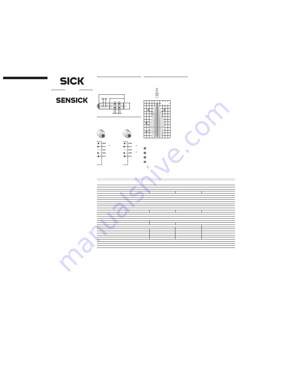
1
M18x1
5
5
73.3
47
5
UM 18-51111
UM 18-51115
UM 18-51112
UM 18-51114
1
L+
Q, Q
NC
4
3
2
M
brn
blk
blu
5
MF
gra
wht
1
L+
Q , Q
Q
, Q
4
3
2
M
brn
blk
blu
5
MF
gra
wht
2
2
1
1
–80
–40
0
40
80
[mm]
50
100
150
200
250
300
350
UM 18-5111_
250 mm
1
2
3
4
2
Operating distance
Maximum scanning
distance
3
1
4
Aligned plate
500 x 500 mm
2
Tube diameter 10 mm
UM 18-
51111
51112
51114
51115
Oper
Oper
Oper
Oper
Operating distance
ating distance
ating distance
ating distance
ating distance
30 mm ... 250 mm (< 350 mm)
(maxim
(maxim
(maxim
(maxim
(maximum scanning distance)
um scanning distance)
um scanning distance)
um scanning distance)
um scanning distance)
Ultrasonic frequency
320 kHz
Resolution
0.36 mm
Reproducibility
typ. ±0,15 % of final value
Accuracy
≤
2 % of final value
≤
2 % of final value
Oper
Oper
Oper
Oper
Operating v
ating v
ating v
ating v
ating voltage
oltage
oltage
oltage
oltage
U
B
= 10 ... 30 V DC
Residual ripple
10 %
Idle current consumption
≤
40 mA
Housing material
Brass tube, nickel plated
Plastic parts: PBT
Ultrasonic converter : polyurethane foam, epoxy resin with glass content
Enclosure rating to EN 60 529
IP 67
Connection type
Plug M12, 5-pin
Display elements
2 LEDs
2 LEDs
Ambient temperature
Operating: –20 °C ... +70 °C
Storage:
–40 °C ... +85 °C
Weight
65 g approx. (with 2 nuts)
Control input MF
Teach-in
Switching outputs PNP, inver table
1 x PNP
1)
2 x PNP
2)
Switching outputs NPN, inver table
1 x NPN
3)
2 x NPN
4)
Temperature compensation
No
yes
yes
no
Synchronisation option
No
yes
yes
no
Functional display
No
yes
yes
no
Scanning mode
Yes
yes
yes
yes
Deflector mode
No
yes
yes
no
Switching hysteresis
2.0 mm ±10 %
Switching frequency
15 Hz
Response time
32 ms
Standby delay
< 300 ms
3
1)
(L+) – 2 V, l
max
= 500 mA, shor t-circuit proof
3)
M + 2 V, l
max
= 500 mA, shor t-circuit proof
2)
(L+) – 2 V, l
max
= 2 x 500 mA, short-circuit proof
4)
M + 2 V, l
max
= 2 x 500 mA, shor t-circuit proof


