It takes 500 ms for the robot to monitor the reduced speed (see robot documentation).
The response time of the safety laser scanner is 70 ms. At an approach speed of
1600 mm/s, a difference in the minimum distances 912 mm results.
Approach
b
Reduced Field radius
=
Stop Field radius
+ S
Diff
Complementary information
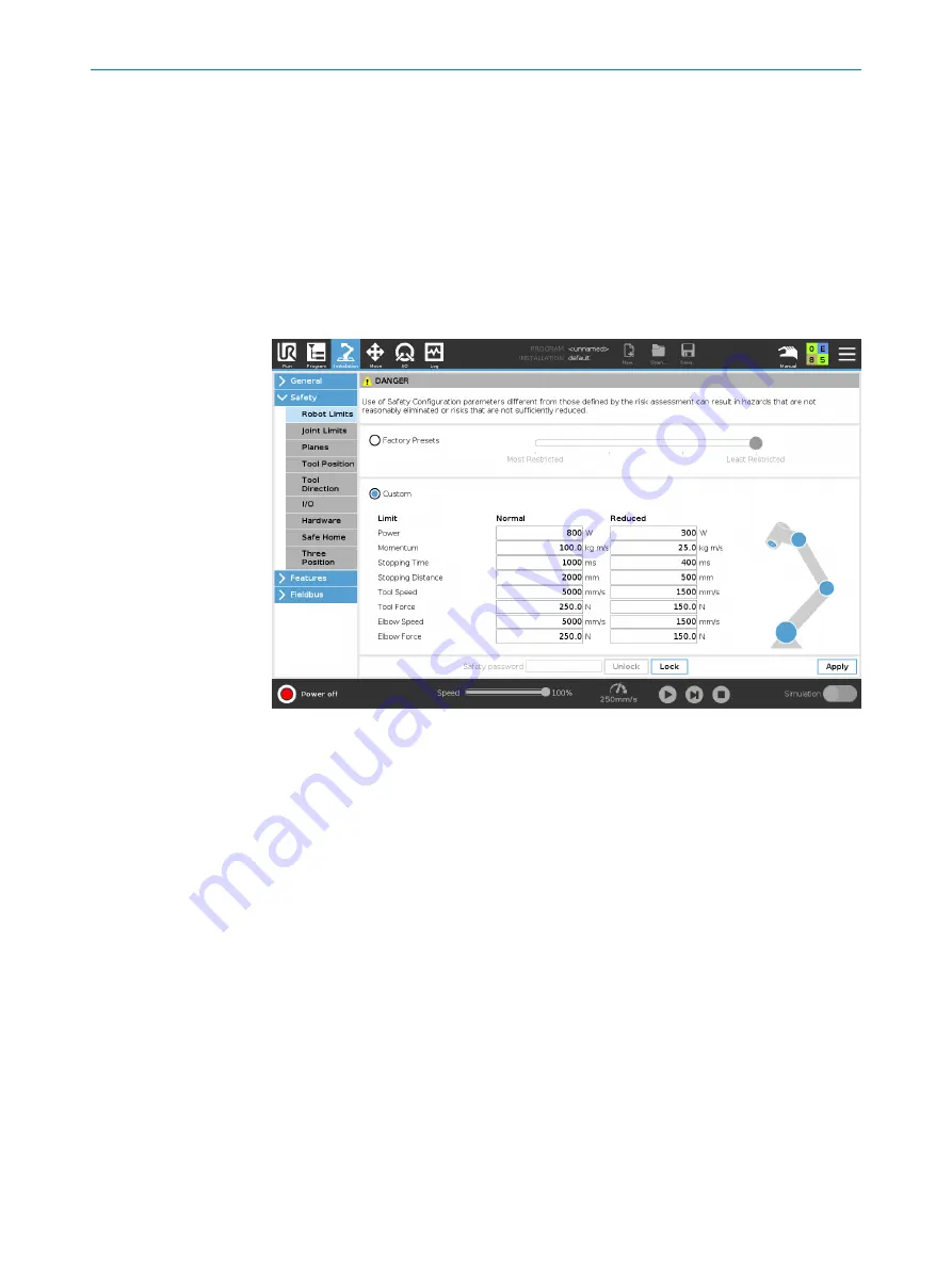
In the safety configuration of the robot controller, you can configure the stopping
time for the maximum speed (Normal Mode) and the safety-rated monitored speed
(Reduced Mode).
Figure 5: Configuration of the stopping time in the robot controller
Further topics
•
"Calculating value for Stop Field radius", page 9
4.1.3
Position of the robot
The robot must be mounted at a fixed position. If the robot is mounted on a moving
table, the safety laser scanner must be mounted on the same table. The robot and the
safety laser scanner must always be positioned in the same relationship to each other.
If the position of the robot is changed, the protective fields must be reestablished
because the environment of the system has changed.
4.1.4
Depending on the variant, a warning field must be configured in the configuration
software. This warning field is not used by the safety system. You can use the signal as
you wish in your application.
Signal behavior
•
LOW: Warning field free
•
HIGH: Object in warning field
4
PROJECT PLANNING
12
O P E R A T I N G I N S T R U C T I O N S | nanoScan3 Tool - URCap
8025720/1A9R/2020-12-15 | SICK
Subject to change without notice


