background image

52

8024638/AE00/V1-0/2019-09| SICK

S E R V I C E   M A N U A L   |  MCS200HW

Subject to change without notice

5  

REPAIRS 

5

Repairs

5.1

Working on the device cabinet

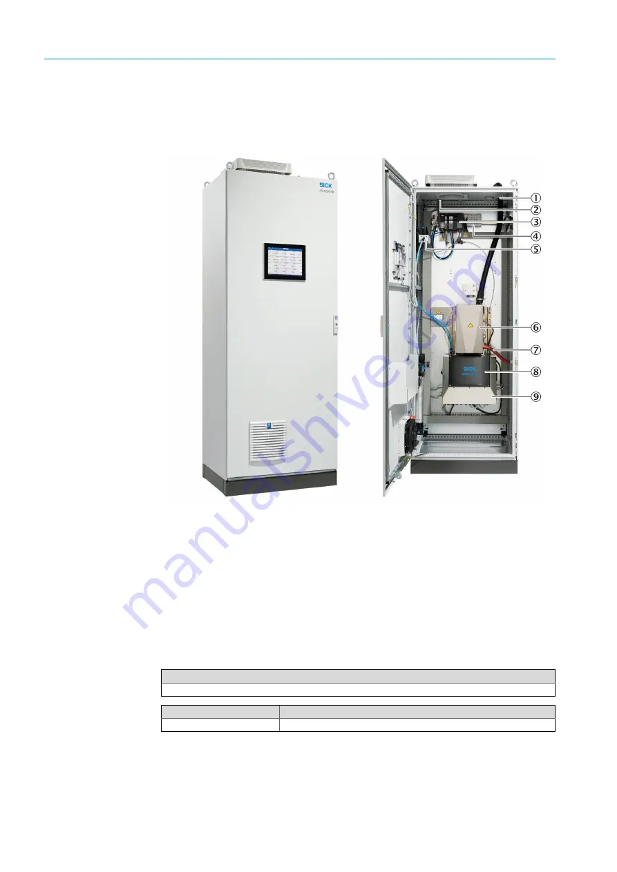
Fig. 59: Equipment cabinet, inside

5.1.1

Replacing the door fan

1

Disconnect the MCS200HW power supply.

2

Disconnect the power supply of the door fan.

1

Heated sample gas line

2

Roof ventilator

3

Valve  manifold

4

IO  modules

5

Pressure reducer unit

6

Cell

7

Test  gas  line

8

Sender/receiver  unit

9

Electronics  unit

Tools required
Phillips screwdriver

Spare parts set No.

Contents

6048627

Door fan

Summary of Contents for MCS200HW

Page 1: ...MMMI MMMSERVICE MANUAL S E R VI C E M A N U A L MCS200HW Multicomponent Analysis System Title page ...

Page 2: ...9183 Waldkirch Germany Phone 49 7641 469 0 Fax 49 7641 469 1149 E mail info pa sick de Trademarks Product names used in this document may be trademarks and are only used for identification purposes Original document This document is an original document of SICK AG SICK AG assumes no liability for the correctness of an unauthorized translation If in doubt contact SICK AG or your local representativ...

Page 3: ...e complete cell 18 3 4 3 Cell inlet filter maintenance 21 3 4 4 Replacing the non return valve on the cell inlet filter 25 3 4 5 Ejector block maintenance 26 3 4 5 1 Replacing the O ring on the middle section 29 3 4 5 2 Replacing the sealing ring on hose connection 2 30 3 4 5 3 Replacing the O rings on exhaust gas connection and ejector nozzle 31 3 4 6 Mirror plates and tubes maintenance 33 3 4 6 ...

Page 4: ... display 62 5 1 8 Replacing the 24V power supply unit 63 5 2 Working on the cell 65 5 2 1 Removing the complete cell 65 5 2 2 Fitting the complete cell 68 5 2 3 Replacing the oxygen sensor 70 5 2 4 Replacing mirror plates 73 5 2 4 1 Replacing the upper mirror plate 73 5 2 4 2 Replacing the lower mirror plate 76 5 2 5 Replacing the heating cartridges 79 5 2 6 Replacing the PT100 temperature sensor ...

Page 5: ...the cable and light barrier on the filter wheel motor 120 5 3 15 Replacing the LPMS04 circuit board 121 5 3 16 Replacing the heating cartridges 122 5 3 17 Replacing the PT100 temperature sensor 125 5 3 18 Replacing the sender receiver windows 127 5 3 19 Adjusting the zero point 128 5 4 Working on the electronics unit 129 5 4 1 Removing and fitting the electronics unit 129 5 4 2 Replacing the LPMS0...

Page 6: ...CONTENTS 6 8024638 AE00 V1 0 2019 09 SICK S E RVI C E M AN UA L MCS200HW Subject to change without notice ...

Page 7: ...ect tree refers to the current directory structure on the left side in SOPAS The SOPAS menu refers to the menu line in SOPAS Furthermore operating the operator panel is not described here Handling the I O modules is also not explained in detail Intervention on the MCS200HW by unauthorized persons voids the guarantee by the SICK AG WARNING Damage as a result of improper working Improper working can...

Page 8: ...ke suitable safety precautions before working on the gas path Provide adequate ventilation at the workplace or work under a vent Wear protective goggles or a safety mask protective gloves and acid proof protective clothes WARNING Explosion hazard through explosive sample gas Do not apply explosive gases to the MCS200HW DANGER Risk of burns due to hot surface Allow the MCS200HW to cool down before ...

Page 9: ... have any questions If you have questions to the Helpdesk provide the following information if possible Device type serial number firmware version Measured components and measuring ranges Ambient conditions temperature air humidity possible acidic gases Error messages display and your own error description Damage history Repairs already made and replaced parts Contact address for calling back ...

Page 10: ...ET Ethernet cable 3 m CAT5 cross over ESD wristband with crocodile clip 2 mm Allen key 2 5 mm Allen key 3 mm Allen key 4 mm Allen key 5 mm Allen key 6 mm Allen key 5 mm socket wrench 5 5 mm socket wrench 7 mm socket wrench 14 mm jaw wrench 16 mm jaw wrench 18 mm jaw wrench 19 mm jaw wrench Phillips screwdriver Torx screwdriver TX20 Slot screwdriver Tweezers Pliers Circlip pliers Scalpel ...

Page 11: ...to be carried out on the MCS200HW as well as the respective intervals are listed in the Preventive Maintenance document 3 2 Expendable and wearing parts Definition Expendable parts Parts that must be replaced irrespective of their condition No guarantee Wearing parts Parts that should be replaced as required depending on their condition Guarantee possibly restricted ...

Page 12: ...ging filter pads 3 3 1 1 Door ventilator Only replace filter mats on the device cabinet when the device is switched off 1 Pull the blue lever to open the ventilator flap Fig 2 Ventilator flap in cabinet door 2 Take old filter pad out Fig 3 Ventilator flap in cabinet door open 1 Roof ventilator 2 Door ventilator Spare parts set No Contents 2099669 Filter mats for MCS200HW cabinet ...

Page 13: ... roof ventilator with Torx TX20 4 pieces 2 Remove the roof ventilator cover 3 Remove old filter mats 4 pieces 4 Insert new filter mats at the edges 4 pieces Labeled sides must point to the fan 5 Replace the cover 6 Close the locks Observe the flow direction when inserting the filter mat The firm labeled side points to the clean air side the open soft side to the dust air side Tools required Torx s...

Page 14: ...200HW cool down 3 Loosen the fastening screws of the cell cover on the right and left with a Phillips screw driver 4 pieces DANGER Risk of burns due to hot surface Allow the MCS200HW to cool down before carrying out any work NOTE Do not switch off the instrument air supply Tools required Phillips screwdriver 1 Cell 2 Sender receiver unit with electronics unit Do not remove the screws only loosen t...

Page 15: ... MCS200HW cool down 3 Loosen the fastening screws of the cell cover on the right and left with a Phillips screw driver 4 pieces 4 Open the cell cover see Chapter Working on the cell page 14 1 Fastening screws right Tools required Jaw wrench size 14 16 18 Phillips screwdriver 5 mm Allen key DANGER Risk of burns due to hot surface Allow the MCS200HW to cool down before carrying out any work Do not r...

Page 16: ...7 Optional Disconnect the test gas line from the 90 degree bracket on the cell inlet filter with a jaw wrench see Fig 6 Cell open page 16 item number 5 8 Disconnect the oxygen sensor on the device Sub D plug 1 Exhaust gas line 2 Oxygen sensor 3 Heated sample gas line 1 4 Heated sample gas line 2 optional 5 Test gas line 6 Fastening clip for exhaust gas line 7 Slots for hose connections Disconnect ...

Page 17: ...eater plug connection Fig 8 Power supply cell heater 11Disconnect the A holder of the cell Loosen the fastening screws on the left with a 5 mm Allen key 3 pieces Loosen the fastening screws on the right with a 5 mm Allen key 3 pieces Fig 9 Cell A holder right 12Lift the cell upwards and remove it from the cabinet The plug connection is located at slot CELL below the sender receiver unit 1 CELL slo...

Page 18: ...binet with retaining plate 2 Position the cell in the device cabinet Hook the bolts of the bracket plate of the cell into the retaining plate in the device cabinet Fig 11 Cell with bracket plate 3 Screw the cell A holder tight Fasten screws left and right with a 5 mm Allen key 3 pieces each Tools required Jaw wrench size 14 16 18 Phillips screwdriver 5 mm Allen key 1 Retaining plate 2 Recess 3 Pow...

Page 19: ...er Connect the plug into the CELL slot below the sender receiver unit Fig 13 Power supply cell heater 2 Insert the oxygen sensor into the device and screw tight Fix the line of the oxygen sensor to the cell with the fastening clip 3 Connect hose lines 1 to 3 to the marked slots see Fig 7 Slots page 16 item number 7 Fix hose lines 1 and 3 to the cell with fastening clips as necessary 1 A holder fas...

Page 20: ... item number 1 Fasten the exhaust gas line to the cell with the fastening clip see Fig 6 Cell open page 16 item number 6 5 Optional Attach the test gas line to the 90 degree bracket see Fig 6 Cell open page 16 item number 5 6 Connect heated sample gas lines 1 and 2 optional to the cell inlet filter see Fig 6 Cell open page 16 item numbers 3 and 4 5 Close the cell cover and screw tight see Fig 5 Ce...

Page 21: ...orking on the cell page 14 5 Disconnect the following hose connections with a suitable jaw wrench Hose connection to the ejector block see Fig 15 item number 3 Test gas connection optional see Fig 15 item number 2 Heated sample gas line 1 or optionally 2 see Fig 15 item numbers 1 and 5 Tools required Jaw wrench size 14 16 Phillips screwdriver 5 mm Allen key Circlip pliers Slot screwdriver Scalpel ...

Page 22: ...tions 6 Loosen the fastening screws on the cell inlet filter with a 5 mm Allen key 4 pieces Fig 16 Cell inlet filter fastening screws 7 Remove the cell inlet filter 1 Heated sample gas line 1 2 Test gas connection with non return valve 3 Hose connection to ejector block 4 Cell inlet filter 5 Heated sample gas line 2 optional 1 to 4 Fastening screw ...

Page 23: ...ell inlet filter lock washer 10Remove the sintered metal filter and O ring white 11Insert spare parts into the cell inlet filter observe the sequence 1 O ring white 2 Sintered metal washer 3 Lock washer Make sure the lock washer engages 1 O ring outer black 2 Nozzle 3 Lock washer 4 Sintered metal filter NOTE Leak tightness of the system Damaged surfaces impair the leak tightness of the system Do n...

Page 24: ... cell with a 5 mm Allen key see Fig 17 Cell inlet filter opened page 23 14Replace the spring washer of the nozzle 15Screw the nozzle tight 16Attach the cell inlet filter to the cell with new screws 17Fasten hose connections 18Close the cell cover and screw tight 1 Sintered metal washer 2 Lock washer 3 O ring white 4 O ring black 5 Cell inlet filter Keep the nozzle for reassembly Observe the sequen...

Page 25: ... filter hose con nections page 22 3 Remove the non return valve and 90 degree bracket together Fig 21 Non return valve and 90 degree bracket new Fig 22 Non return valve arrow marking flow direction 4 Insulate the new non return valve Wrap both ends with Teflon tape Leave the first two threads free Tools required Jaw wrench size 14 Spare parts set No Contents 2099679 Cell inlet filter and non retur...

Page 26: ...the O ring of the middle section Replace the O ring and sealing ring on hose connection 2 Replace the O rings on the exhaust gas connection and ejector nozzle 1 Disconnect the MCS200HW power supply 2 Let the MCS200HW cool down 3 Loosen the fastening screws of the cell cover on the right and left with a Phillips screw driver 4 pieces Arrow marking on the non return valve marks the flow direction se...

Page 27: ...the plug connection on the device cabinet Loosen the fastening clip with a Phillips screwdriver 6 Disconnect hose connections 2 and 3 with a jaw wrench see Fig 24 Ejector block hose connections page 27 item numbers 3 and 4 Fig 25 Hose slots 1 Ejector block 2 Oxygen sensor 3 Hose connection 2 4 Hose connection 3 5 Hose connection to cell inlet filter 6 Exhaust gas line The hose connections are mark...

Page 28: ... fastening screws of the ejector block with a 5 mm Allen key 3 pieces see Fig 26 Ejector block fastening screws page 28 Fig 26 Ejector block fastening screws 10Remove the ejector block 11Remove the old O rings and support sleeve see Fig 27 Ejector block O rings page 28 item numbers 1 and 2 Carefully remove O ring residues from the cell and ejector block Fig 27 Ejector block O rings 1 Screw Keep th...

Page 29: ...ozzle O ring outside page 33 3 4 5 1 Replacing the O ring on the middle section 1 Loosen the fastening screws of the ejector block middle section with a 2 5 mm Allen key 2 pieces Fig 29 Ejector block middle section 2 Remove the middle section from the ejector block Suitable aids for removing O ring residues Flat tool slot screwdriver scalpel or similar Acetone Tools required Phillips screwdriver S...

Page 30: ...with new screws 3 4 5 2 Replacing the sealing ring on hose connection 2 1 Disconnect hose connection 2 with a jaw wrench Fig 31 Ejector hose connection 2 2 Remove the old sealing ring from the hose connection 2 Carefully remove sealing ring residues 1 O ring 2 Nozzle Tools required Phillips screwdriver Slot screwdriver Jaw wrench size 14 19 5 mm Allen key 3 mm Allen key 2 mm Allen key Scalpel 1 Se...

Page 31: ...th a 2 mm Allen key 2 pieces Fig 32 Ejector block fastening screws exhaust gas connection 2 Assemble the removal tool for the ejector nozzle Fig 33 Removal tool ejector nozzle 3 Position the removal tool on the underside of the ejector block see Fig 34 Suitable aids for removing O ring residues Flat tool slot screwdriver scalpel or similar Acetone Tools required Phillips screwdriver Slot screwdriv...

Page 32: ... and exhaust gas connection 6 Fit a new O ring on the front of the ejector nozzle 7 Fit a new O ring on the exhaust connection 8 Insert the ejector nozzle 9 Fasten the middle section with new screws 10Fit a new O ring on the outside of the ejector nozzle NOTE Leak tightness of the system Damaged surfaces impair the leak tightness of the system Do not damage surfaces Suitable aids for removing O ri...

Page 33: ...plates and tubes maintenance The mirror plates can only be serviced with the cell removed The complete cell must be removed to replace the O rings of the upper mirror plate 1 Ejector nozzle O ring outside Observe the sequence First put the spring washer then the washer on the screw NOTE Material damage Do not touch the coated surfaces of the mirror plates Tools required 5 mm Allen key Phillips scr...

Page 34: ...ver 4 pieces Fig 37 Cell fastening screws cover plate 1 3 Loosen the fastening screw on the rear of the upper cover plate with a Phillips screw driver 1 piece Fig 38 Cell fastening screws cover plate 1 4 Remove the upper cover plate 5 Loosen the fastening screws on the upper mirror plate with a 5 mm Allen key 6 pieces 1 Fastening screws of upper cover plate Keep screws spring washers and washers f...

Page 35: ...tening screws with a 5 mm Allen key Tighten fastening screws parallel Ensure the screws grip properly and avoid thread seizure 7 Remove the upper mirror plate 1 Fastening screws Keep screws spring washers and washers for reassembly 1 Thread openings Alternative Unscrew and remove all cell covers see Chapter Removing the complete cell page 65 Apply the flat side of a screwdriver to the side recesse...

Page 36: ...e mirror plate 10Fit the upper mirror plate 1 Mirror plate 2 Coated surface 3 O ring 4 Recesses for levering out NOTE Leak tightness of the system Damaged surfaces impair the leak tightness of the system Do not damage surfaces Suitable aids for removing O ring residues Flat tool slot screwdriver scalpel or similar Acetone NOTE Material damage Protect mirror plates from insulation particles Do not ...

Page 37: ...ror plate 1 Place the removed cell down with the underside facing upwards Fig 43 Cell underside 2 Remove the sealing rings from the tubes 3 Loosen the fastening screws of the lower cover plate with a Phillips screwdriver 4 pieces 4 Remove the lower cell cover plate 5 Loosen the fastening screws on the lower mirror plate with a 5 mm Allen key 6 pieces 1 Mirror plate labeling 2 Cell front side with ...

Page 38: ... 7 Remove the lower mirror plate 8 Remove the old O ring from the mirror plate Carefully remove O ring residues from the mirror plate and cell Protect the upper mirror plate against O ring residues 1 Fastening screws Keep screws spring washers and washers for reassembly 1 Thread openings Alternative Unscrew and remove all cell covers see Chapter Removing the complete cell page 65 Apply the flat si...

Page 39: ...plate tight 13Screw the lower cell cover plate tight 14Fit the tubes O rings 15Refit the cell see Chapter Working on the sender receiver unit page 43 Suitable aids for removing O ring residues Flat tool slot screwdriver scalpel or similar Acetone 1 Lower mirror plate 2 O ring NOTE Material damage Protect mirror plates from insulation particles Do not touch the insulation material Observe alignment...

Page 40: ... 48 Tubes 2 Lever out the tubes 1 Screw the screws into the thread openings provided 2 pieces Fig 49 Thread openings tubes 2 Tighten the fastening screws with a 3 mm Allen key Tighten fastening screws parallel Ensure the screws grip properly and avoid thread seizure 3 Take off the tubes Carry out tube maintenance at the same time as maintenance of the lower mirror plate Tools required 3 mm Allen k...

Page 41: ...stal glass out of the tube from below This could destroy the crystal glass b Remove O ring 1 Fig 51 Removing the tube crystal glass 5 Fit new O rings and new crystal glass observe sequence 1 Insert O ring 1 inside the tube 2 Place 0 ring 2 outside around the tube NOTE Leak tightness of the system Damaged surfaces impair the leak tightness of the system Do not damage surfaces Suitable aids for remo...

Page 42: ...e tube points upwards Fig 54 Aligning the tube on the mirror plate 8 Turn the tube to align it so that the holes for the screws are over each other The tube must end flush with the mirror plate 9 Screw the tube tight onto the lower mirror plate 10Repeat procedure for second tube 11Fasten the lower mirror plate to the cell with a new O ring see Chapter Replacing the O rings of the lower mirror plat...

Page 43: ...cing the filter mat on the ventilator Fig 55 Ventilator sender receiver unit 1 Open the ventilator cover on the outside Remove the ventilator from the side 2 Replace the filter mat Fig 56 Ventilator cover and filter mat 3 Fit the outside ventilator cover DANGER Risk of burns due to hot surface Allow the MCS200HW to cool down before carrying out any work Spare parts set No Contents 5309683 Filter m...

Page 44: ... page 44 2 Loosen the fastening screws of the drying agent container on the inside of the lid with a Phillips screwdriver 2 pieces Fig 58 Drying agent container Do not remove the screws only loosen them 1 Fastening screws The drying agent must be replaced each time the sender receiver unit is opened Pay attention to dust protection Refit the sender receiver unit cover during work on the unit The d...

Page 45: ... 0 2019 09 SICK SE RVIC E MAN U AL MCS200HW Subject to change without notice MAINTENANCE 3 3 Fill the drying agent 1 sachet 4 Screw the drying agent container tight 5 Close the sender receiver unit cover and screw tight ...

Page 46: ...in the specified warning thresholds 3 Readjust the adjustment factors when deviations are higher than 0 02 or when a maintenance request appears 4 2 Oxygen sensor drift check 1 Select Diagnosis State control O2 Sensor 2 Check the adjustment factor The adjustment factor must be more than 0 5 vol mA below the specified warning threshold 3 Readjust the adjustment factors when the adjustment factor is...

Page 47: ...sis State control Beamer 2 Check beamer current The beamer current must be within the specified warning thresholds 3 Replace the beamer when the radiator current is less than 0 05 A above the Current Min Warning or a maintenance request is pending 4 4 Reference energy check 1 Select Diagnosis Control values Reference energy 2 Check the reference energy ...

Page 48: ...rgy The reference energy of the respective component must be at least 5 percentage points above the individual warning threshold 3 Proceed as follows when the reference energy is lower or a maintenance request is pending 1 Check the beamer current see Chapter Beamer current check page 47 2 When the beamer current is OK check optical components Window soiling Soiling of the gold layer of the mirror...

Page 49: ...rameterization Formulas Formula 130 Modbus Simulation Fixed values can be specified for the measured values These are available in the Modbus registers and can be searched for by the customer Proceed as follows to change the register sequence in the data transfer 1 Select Parameterization Modbus 2 Select Register swap 3 Select the register sequence ...

Page 50: ...puts and outputs 4 5 3 1 Analog outputs Under Analog outputs AOi current values can be specified which are present at the respective analog outputs 1 Select Maintenance Tests Analog outputs AOi 2 Select Tests The input window opens 3 Enter the value 4 5 3 2 Digital outputs For the procedure to simulate the digital outputs see Analog outputs page 50 ...

Page 51: ... Under Analog inputs AIi externally simulated current values can be displayed and checked as mA value and converted to the physical quantity 1 Select Maintenance Tests Analog inputs AIi 2 Select Tests The input window opens 3 Enter values 4 5 3 4 Digital inputs For the procedure to simulate the digital inputs see Analog inputs page 51 ...

Page 52: ...cabinet inside 5 1 1 Replacing the door fan 1 Disconnect the MCS200HW power supply 2 Disconnect the power supply of the door fan 1 Heated sample gas line 2 Roof ventilator 3 Valve manifold 4 IO modules 5 Pressure reducer unit 6 Cell 7 Test gas line 8 Sender receiver unit 9 Electronics unit Tools required Phillips screwdriver Spare parts set No Contents 6048627 Door fan ...

Page 53: ...eads individually 1 Press the push button 2 Pull the lead out Fig 62 Door fan detail 5 Remove the fan 1 Open the bayonet lock by turning the complete fan 2 Remove the fan 6 Insert new fan 1 ELECTRONIC electronics power supply 2 FAN housing fan power supply 3 Grounding 4 CELL cell 5 DEVICE sender receiver unit 1 Push button 2 Flow direction arrow marking Observe flow direction when inserting Here I...

Page 54: ...ressure reducer unit 1 Close off instrument air provided by the customer 2 Loosen the fastening screws behind the pressure reducer unit with a 4 mm Allen key 4 pieces Fig 64 Pressure reducer unit 3 Disconnect the hose connections 4 Screw the new pressure reducer unit tight Tools required Phillips screwdriver 4 mm Allen key Spare parts set No Contents 5329115 Pressure reducer unit 1 Instrument air ...

Page 55: ... unit valve 5 Connect the hoses 6 Connect the instrument air 5 1 3 Replacing the CAN node Fig 66 CAN node 1 Disconnect the MCS200HW power supply 2 Disconnect the bus cable 1 Valve position open Tools required Phillips screwdriver Spare parts set No Contents 2099746 Gateway Module 750 837 1 CAN node 2 Valve manifold 3 IO modules ...

Page 56: ... into the opening next to it 2 Disconnect the cable 4 Disconnect the leads 5 Pull the orange lever to pull out the CAN bus Fig 68 CAN node detail 6 Check the switch on the new CAN node Use the settings of the old CAN node 1 Bus cable 2 Openings 3 Power supply Document the assignment of the leads at the CAN node before disconnecting e g with a photo 1 Leads 2 Orange lever 3 Switch ...

Page 57: ... power supply 5 Close off instrument air provided by the customer 6 Disconnect the hose connections 7 Loosen the fastening screws with a Phillips screwdriver 4 pieces Fig 69 Valve manifold 8 Pull the valve manifold out to the front 9 Insert a new valve manifold To connect press with a screwdriver into the opening Tools required Phillips screwdriver Spare parts set No Contents 60663388 Valve block ...

Page 58: ...lacing the valve 1 Disconnect the MCS200HW power supply 2 Disconnect the bus cable on the CAN node see Fig 68 CAN node detail page 56 3 Disconnect the power supply of the CAN node at the 24V power supply unit 4 Connect the MCS200HW power supply 5 Close off instrument air provided by the customer 6 Loosen the valve fastening screws with a Phillips screwdriver 2 pieces 1 Valve manifold locking Tools...

Page 59: ...he orange holder to pull the IO module out to the front 1 Valve manifold 2 Removal lever 3 Valve 4 Valve screw 5 Fastening screw 6 Placeholder Tools required Phillips screwdriver Spare parts set No Contents 2098608 Digital input module 4 channels positive switching contact load 24 V DC 4 5 mA for actuator application 2098609 Digital input module 4 channels positive switching contact load 24 V DC 4...

Page 60: ...on see Chapter Test signal transmission page 48 5 1 6 Replacing the test gas valves 1 Disconnect the MCS200HW power supply 2 Close the valves of the connected test gas cylinders 3 Loosen the locking screw of the power supply plug with a Phillips screwdriver Fig 73 Power supply plug and excitation coil fastening Tools required Phillips screwdriver Spare parts set No Contents 6065506 2 2 path mini s...

Page 61: ...ly plug Fig 74 Power supply plug 5 Loosen the fastening nut of the excitation coil with an 11 mm open end wrench 6 Loosen the fastening screws of the valve block with Torx Tx8 Fig 75 Valve block fastening screws 7 Remove the valve block and sealing rings 2 pieces Fig 76 Valve block sealing rings 1 Power supply plug 1 Fastening screw ...

Page 62: ... to the digital output and to the excitation coil Tighten the locking screw 12Open the valves of the test gas cylinders 13Connect the MCS200HW power supply 5 1 7 Replacing the display 1 Disconnect the MCS200HW power supply 2 Disconnect the cable connections Fig 77 Display cable connections 3 Loosen the screws of the display fastening clips with a Phillips screwdriver 10 pieces 1 Sealing ring 1 2 S...

Page 63: ... cables 8 Connect the MCS200HW power supply 9 Parameterize the IP addresses of the display 5 1 8 Replacing the 24V power supply unit 1 Disconnect the MCS200HW power supply Fig 79 Device cabinet 24V power supply unit 1 Fastening clip Tools required Phillips screwdriver Spare parts set No Contents 2099745 Power supply unit 85 264 V 24 V 2 5 A Observe the safety rules for work on electrical systems s...

Page 64: ...rew the leads 4 Pull out the top and bottom orange brackets Fig 81 24V power supply unit removed 5 Remove the 24V power supply unit 6 Insert and fasten the new power supply unit 7 Reinsert the leads and screw tight 8 Close the cover 9 Connect the MCS200HW power supply Document the position of the leads before removing them e g with a photo 1 Orange bracket top 2 24V power supply unit ...

Page 65: ...the cell inlet filter using a jaw wrench see Fig 6 Cell open page 16 3 Place the cell down with the upper side facing downwards 4 Remove the A holder on both sides Loosen the fastening screws with a 5 mm Allen key 3 pieces Fig 82 Cell A holder DANGER Risk of burns due to hot surface Allow the MCS200HW to cool down before carrying out any work Tools required Phillips screwdriver 5 mm Allen key Jaw ...

Page 66: ...the cell on the left and right Perform the following steps on both sides see Fig 84 Cell side cover page 66 Loosen fastening clips 1 with a Phillips screwdriver 2 pieces Fastening screws 2 of the cell cover 2 pieces have already been loosened do not unscrew Loosen fixing screws 3 of the side cover with a Phillips screwdriver 2 pieces Loosen fastening screws 4 of the bracket plate with a 5 mm Allen...

Page 67: ...e fastening screw on the rear of the upper cover plate with a Phillips screw driver 1 piece Fig 86 Cell upper cover plate fastening screws 2 12Loosen the remaining fastening screws of the rear cover 3 pieces Fig 87 Cell rear cover fastening screws 1 Fastening screws of upper cover plate Keep screws spring washers and washers for reassembly 1 Fastening screw upper cover plate rear side Keep screws ...

Page 68: ...he cable of the heating spiral on the rear side is open Upper cover plate and right cover remain together 16Lift out the inner part of the cell 5 2 2 Fitting the complete cell 1 Replace the inner part of the cell in the upper cover plate and the right cover Fig 89 Inserting the cell 2 Screw the right and left covers tight 3 Insert the cable conduit into the recess Observe the position of the seali...

Page 69: ...nd on the rear side Fig 91 Screwing the bracket plate tight 6 Screw the upper cover plate tight Fig 92 Cell upper cover plate fastening screws 7 Screw the A holder tight on both sides Fig 93 Cell A holder The washers of the fastening screws are on the outside 1 Fastening screw rear side 2 Fastening screw left The recesses of the A holder must be on the outside 1 A holder 2 Recess ...

Page 70: ... Teflon tape and screw tight see Chapter Replacing the non return valve on the cell inlet filter page 25 Fig 95 Insulating the non return valve 5 2 3 Replacing the oxygen sensor The cell inlet filter can be replaced with the cell fitted 1 Fastening screw 2 Sealing ring Tools required Phillips screwdriver Spare parts set No Contents 2081837 Oxygen sensor with double end ring spanner DANGER Risk of ...

Page 71: ...receiver unit 3 Disconnect the plug Fig 97 Oxygen sensor slot 4 Loosen the fastening clip of the oxygen sensor on the cell with a Phillips screwdriver Fig 98 Cell oxygen sensor 5 Remove the oxygen sensor from the cell using a spanner spare parts set 6 Attach the new oxygen sensor to the cell 7 Fasten the oxygen sensor cable with the fastening clip 8 Connect sender receiver unit and fasten with soc...

Page 72: ... oxygen sensor 1 Select Parameterization O2 sensor 2 Check nominal value The nominal value must be 20 95 3 Select Adjustment Start adjustment 4 Click Adjust O2 Oxygen sensor is adjusted In the case of the maintenance message S047 Deviation O2 Just too large due to exceeding the limit value the message can be reset under Maintenance Acknowledge active message ...

Page 73: ...te cell page 15 2 Loosen the fastening screws of the upper cover plate with a Phillips screwdriver 4 pieces Fig 99 Cell fastening screws cover plate 1 NOTE Material damage Do not touch the coated surfaces of the mirror plates Tools required 5 mm Allen key Phillips screwdriver Slot screwdriver Scalpel Spare parts set No Contents 2045740 Maintenance kit windows and seals DANGER Risk of burns due to ...

Page 74: ...plate 5 Loosen the fastening screws on the upper mirror plate with a 5 mm Allen key 6 pieces Fig 101 Fastening screws upper mirror plate 6 Lever out the mirror plate 1 Screw the screws into the thread openings provided on the mirror plate 2 pieces Fig 102 Thread openings upper mirror plate 1 Fastening screw upper cover plate rear side Keep screws spring washers and washers for reassembly 1 Fasteni...

Page 75: ... ring Alternative Unscrew and remove all cell covers see Chapter Removing the complete cell page 65 Apply the flat side of a screwdriver to the side recesses of the mirror plate Lever out the mirror plate NOTE Material damage Do not touch the coated surfaces of the mirror plates 1 Mirror plate 2 Coated surface 3 O ring 4 Recesses for levering out NOTE Material damage Protect mirror plates from ins...

Page 76: ...ening screw on the rear side 1 piece 5 2 4 2 Replacing the lower mirror plate 1 Place the removed cell down with the underside facing upwards Fig 105 Cell underside 2 Remove the sealing rings from the tubes 3 Loosen the fastening screws of the lower cover plate with a Phillips screwdriver 4 pieces 4 Remove the lower cell cover plate 1 Mirror plate labeling 2 Cell front side with cell inlet filter ...

Page 77: ... into the thread openings provided on the mirror plate 2 pieces Fig 107 Thread openings lower mirror plate 2 Tighten the screws with a 5 mm Allen key Tighten fastening screws parallel Ensure the screws grip properly and avoid thread seizure 7 Remove the lower mirror plate 1 Fastening screws 1 Thread openings Alternative Unscrew and remove all cell covers see Chapter Removing the complete cell page...

Page 78: ...Fitting the complete cell page 18 14Connect the MCS200HW power supply 15Switch the MCS200HW on 16Allow the MCS200HW to heat up for at least 2 hours 17Perform zero point adjustment see Chapter Adjusting the zero point page 128 18Check reference energy see Chapter Reference energy check page 47 1 Lower mirror plate 2 O ring NOTE Material damage Protect mirror plates from insulation particles Do not ...

Page 79: ...with the cell inlet filter and ejector is at the bottom Fig 111 Cell overview left 3 Loosen the fastening clips of the heating cartridges with a Phillips screwdriver 9 pieces Tools required Phillips screwdriver Slot screwdriver Pliers Spare parts set No Contents 2099812 Heating cartridge garlands set 2 HP 115 V 180 W 10 x 80 DANGER Risk of burns due to hot surface Allow the MCS200HW to cool down b...

Page 80: ...pen the contact plug Carefully lever open the clamps of the contact plug with a slotted screwdriver 3 pieces Fig 113 Opening the contact plug 1 Heating cartridge 2 Fastening clip If a heating cartridge is stuck it can be pushed out from the other side e g with a screwdriver Proceed as follows in this case Remove the cell inlet filter see Chapter Cell inlet filter maintenance page 21 Remove the eje...

Page 81: ...cartridges Insert heating cartridges in pairs Pairs each have adjacent slots 7 Fasten the cables of the new heating cartridges with fastening clamps 8 Guide the cables of the new heating cartridges in pairs through the cable conduit to the plug 9 Bundle the cables on the back of the cell with cable ties 1 Fastening clip 2 Leads for thermo switches 2 pieces and heating cartridges 4 pieces 3 Groundi...

Page 82: ... clip in the contact plug 12Close the contact plug 13Fasten the cell covers see Chapter Fitting the complete cell page 68 14Fit the cell see Chapter Fitting the complete cell page 18 5 2 6 Replacing the PT100 temperature sensor To replace the PT100 the complete cell must be removed and all covers removed Heating cartridge pairs have the clamps next to each other Tools required Phillips screwdriver...

Page 83: ...h the rear side upwards The side with the cell inlet filter and ejector is at the bottom Fig 118 Cell overview left 3 Loosen the fastening clips with a Phillips screwdriver 2 pieces 4 Remove the PT100 5 Remove the PT100 cable from the cable conduit 1 Open the contact plug Carefully lever open the clamps of the contact plug with a slotted screwdriver 3 pieces Fig 119 Opening the contact plug 1 Fast...

Page 84: ...ide the cable of the new PT100 through the cable conduit to the plug 11Bundle all the cables on the back of the cell with cable ties Fig 121 Bundling the cables of the heating cartridges 12Fasten the cable of the new PT100 with clamping screws in the contact plug see Fig 122 Contact plug assignment with circuit diagram page 85 Shorten the cables to the appropriate length 1 Fastening clip 2 Leads f...

Page 85: ...plete cell page 68 16Fit the cell see Chapter Fitting the complete cell page 18 5 2 7 Replacing the thermostatic switch The thermostatic switch can be replaced when the cell is installed Fig 123 Thermostatic switch Tools required Phillips screwdriver Pliers Slot screwdriver Spare parts set No Contents 6053091 Thermostatic switch 235 C for cell DANGER Risk of burns due to hot surface Allow the MCS2...

Page 86: ...es 2 Remove the cover Fig 125 Thermostatic switch open 4 Remove the thermostatic switch Disconnect the plug connections on both sides of the thermostatic switch Loosen the studs with pliers 5 Fit a new thermostatic switch Plug in the plug connections 1 Cover 2 Release button 3 Fastening screws 1 Studs 2 Plug connection If necessary use a slotted screwdriver or similar when pulling off For a better...

Page 87: ...ct to change without notice REPAIRS 5 Screw the studs tight 6 Screw the cover tight 7 Check the release button Make sure it does not protrude has triggered Push the release button in if necessary If the thermostatic switch has triggered the power supply is interrupted ...

Page 88: ...over 1 Remove the electronics housing cover with a 2 5 mm Allen key Loosen and remove the fastening screws on the front 7 pieces Fig 126 Electronics housing cover sender receiver unit 1 Loosen and remove the fastening screws on the top 2 pieces Fig 127 Electronics housing cover sender receiver unit 2 Loosen the fastening screws on the left 3 pieces and right 4 pieces Tools required Phillips screwd...

Page 89: ... the front 5 3 2 Replacing the beamer Fig 129 Beamer 1 Open the sender receiver unit see Chapter Opening the sender receiver unit page 44 2 Disconnect the plug connection of the power supply 1 Side fastening screws Tools required Phillips screwdriver 5 mm Allen key Spare parts set No Contents 2099790 Beamer and drying agent The drying agent must be replaced each time the sender receiver unit is op...

Page 90: ...hapter Replacing the drying agent page 44 9 Close the sender receiver unit unit and screw tight 10Switch the MCS200HW on 11Check the beamer current see Chapter Beamer current check page 47 12Reset the beamer service life see Chapter Resetting the beamer service life page 90 13Reset the reference energy see Chapter Resetting the reference energy page 91 5 3 2 1 Resetting the beamer service life 1 S...

Page 91: ...change without notice REPAIRS 5 5 3 2 2 Resetting the reference energy 1 Select Maintenance Functions 2 Click Purging The device is set to the Purge state Fig 131 SOPAS purging 3 Wait for the purging time to elapse 2 minutes 4 Select Diagnosis Control values Reference energy ...

Page 92: ... change without notice 5 REPAIRS Fig 132 SOPAS resetting the reference energy 5 Click Reset 6 Select Maintenance Functions Fig 133 SOPAS special operating states 7 Click Measuring The device is set to the Measuring state Reset only appears when the system is in the Purge state ...

Page 93: ... 88 3 Disconnect all plug connections 4 Open the sender receiver unit see Chapter Opening the sender receiver unit page 44 5 Loosen the fastening screws inside with a 6 mm Allen key Fig 134 Sender receiver unit fastening screws inside right Tools required Phillips screwdriver 6 mm Allen key 2 5 mm Allen key Tweezers DANGER Risk of burns due to hot surface Allow the MCS200HW to cool down before car...

Page 94: ... the sender receiver unit with the outer panel out of the device cabinet see Fig 138 Transmit receive unit front side page 95 Lay the sender receiver unit on a level work surface Turn the sender receiver unit with the underside upwards 9 Loosen the fastening screws of the two templates on the rear side with a 2 5 mm Allen key 2 pieces 1 Fastening screw Pay attention to dust protection Replace the ...

Page 95: ...it receive unit front side 11Remove the inner bracket Fig 139 Sender receiver unit inner bracket 12Disconnect the hose connections of the sender receiver unit from the outer plate 13Remove the complete outer plate 1 Tilt the outer plate upwards 2 Pull it off to the back 3 Pull the power supply cable through the recess 1 Fastening screw template 2 Mushroom head mounts 1 Fastening screws outer plate...

Page 96: ...ening screws with a Phillips screwdriver 3 pieces 2 Remove the fastening screws with tweezers 3 Pull sheet metal cover 3 off to the rear 4 Pull the cable of the heating spirals out of the recess of sheet metal cover 3 Fig 142 Sender receiver unit sheet metal cover 3 16Remove sheet metal cover 4 1 Loosen the fastening screws with a Phillips screwdriver 2 pieces 2 Take off sheet metal cover 4 1 Plug...

Page 97: ...stening screws with a Phillips screwdriver 2 pieces 2 Take off sheet metal cover 5 Fig 144 Sender receiver unit sheet metal cover 5 open 18Pull sheet metal cover 1 with foam insulation out to the side 1 Fastening screw sheet metal cover 5 2 Fastening screw sheet metal cover 4 3 Sheet metal cover 4 Keep the sleeves for reassembly 1 Sheet metal cover 1 2 Fitting position sleeves 3 Sleeve 4 Foam insu...

Page 98: ... on the rear side see Fig 137 Sender receiver unit rear side page 95 9 Hook the sender receiver unit with the mushroom head brackets into the device cabinet 10Screw the sender receiver unit tight on the device cabinet see Fig 136 Sender receiver unit fastening screws page 94 11Connect the plug connections 12Screw the electronics housing cover tight 13Replace the drying agent see Chapter Replacing ...

Page 99: ...the new fan cover 2 Tighten the fastening screws 7 Replace the electronics housing cover and screw tight 8 Fit a new filter mat on the outside 9 Close the outside ventilator cover 10Connect the MCS200HW power supply 5 3 6 Replacing the pressure control module Fig 146 Pressure control module 1 Disconnect the MCS200HW power supply 2 Close off 4 bar instrument air 1 Fan 2 Power supply Tools required ...

Page 100: ...age 88 5 Disconnect all hose connections from the slots Fig 148 Pressure control module hose connections 1 Inlet of instrument air with zero gas quality 2 Inlet of instrument air solely as induction air for ejector 3 Manual valve for instrument air selection 4 3 pressure reducers adjustable 5 Manual valve closed 6 Manual valve open 1 Hose connections 2 Ball valve 3 Pressure control module hose con...

Page 101: ...tening screws 9 Remove the pressure control module 10Screw the new pressure control module tight 11Connect the plug connection 12Connect the hose connection of the pressure control module 13Connect the hoses to the slots Fig 150 Hose slots 14Replace the electronics housing cover and screw tight With the cell cover closed mark the hoses before removing them 1 Fastening screw Sequence if the hose co...

Page 102: ...ustment LED lights up green The LED goes out when adjustment is complete Fig 151 Adjusting the pressure 2 Check in the logbook whether the adjustment was successful 5 3 7 Replacing the complete beamer unit Fig 152 Beamer unit Tools required 5 mm Allen key Spare parts set No Contents 2099791 Beamer unit complete for MCS200HW with drying agent sachet 1 Chopper wheel 2 Motor 3 Beamer 4 Power supply p...

Page 103: ...ee Chapter Performing optical adjustment page 103 12Close the sender receiver unit cover and screw tight 13Connect the MCS200HW power supply 14Reset the beamer service life see Chapter Resetting the beamer service life page 90 5 3 8 Performing optical adjustment 1 Start the test measurement to stop the rotating cycle of the filter wheels 1 Select Global definitions 2 Click Test measuring Fig 153 P...

Page 104: ...S display Select Diagnosis Hardware Adjust VVM Magnitude to the maximum possible value Fig 155 SOPAS VVM Magnitude b LED on LPMS04 Green LED shows increasing energy Red LED shows decreasing energy 4 Click Test measurement to deactivate 5 Replace the drying agent see Chapter Replacing the drying agent page 44 6 Close the sender receiver unit cover and screw tight 1 Adjusting screws 2 Adjusting scre...

Page 105: ... page 102 steps 2 to 6 4 Loosen the fastening screw of the chopper wheel cover on the upper side 2 mm Allen key Fig 157 Chopper wheel 5 Remove the chopper wheel cover 6 Loosen the fastening screw of the chopper wheel cover on the lower side 2 mm Allen key Tools required 2 mm Allen key 5 mm Allen key Spare parts set No Contents 2099792 Chopper motor kit The drying agent must be replaced each time t...

Page 106: ... 159 Pulling the chopper wheel off 8 Loosen the fastening screws of the chopper motor with a 2 mm Allen key 3 pieces Fig 160 Chopper motor fastening screws 9 Remove the chopper motor 10Fit a new chopper motor 1 Align the chopper motor cable position see Fig 152 Beamer unit page 102 2 Screw the chopper motor tight 1 Fastening screw 1 Beamer unit 2 Chopper wheel 1 Fastening screw ...

Page 107: ...receiver unit cover and screw tight 17Connect the MCS200HW power supply 5 3 10 Replacing the filter wheel motor Fig 161 Filter wheel housing 1 and 2 fastening screws left and plug connectors The axle is chamfered Tools required 2 mm Allen key 2 5 mm Allen key 5 mm Allen key NOTE Material damage Do not touch the optical surfaces of the filter wheels 1 Filter wheel 1 2 Filter wheel 1 fastening screw...

Page 108: ... 2 fastening screws left and plug connectors page 107 4 Loosen the fastening screws of the filter wheel housing with a 5 mm Allen key 2 pieces 5 Remove the filter wheel housing Fig 163 Filter wheel housing 1 inner side 1 Filter wheel 1 fastening screw right 2 Filter wheel 2 fastening screw right Spare parts set No Contents 2099793 Filter wheel 1 stepper motor kit The drying agent must be replaced ...

Page 109: ...ection 1 Photoelectric switch 2 Motor and light barrier cable connection 3 Lens 4 Filter wheel motor NOTE Material damage Do not touch the optical surfaces of the filter wheels Alternative a Loosen two screws inside the filter wheel housing see Fig 163 Filter wheel housing 1 inner side page 108 b Remove the filter wheel from the clamping hub the clamping hub remains on the motor shaft c To remove ...

Page 110: ...g the filter wheel motor 11Plug the cable into the filter wheel motor 12Insert the filter wheel into the filter wheel housing and screw tight 1 Insert with the open side facing downwards 2 Align the filter wheel so that the fastening screw can be accessed through the opening in the housing 13Insert the filter wheel housing into the sender receiver unit and screw tight 14Connect the lug connection ...

Page 111: ...wheel housing 2 inner side 5 Remove the filter wheel 1 Align the filter wheel in the housing so that the fastening screw can be accessed through the opening 2 Loosen the fastening screw with a 2 mm Allen key loosen the screw only do not remove 3 Remove filter wheel 2 The spare parts set contains the connecting cable with fork light barrier If necessary the connecting cable can also be replaced Spa...

Page 112: ...llen key 4 pieces Fig 171 Filter wheel motor fastening screws 7 Disconnect the filter wheel motor cable see Fig 164 Filter wheel housing 1 rear side page 109 8 Remove the filter wheel motor 9 Screw the new filter wheel motor tight Observe the cable position when aligning the filter wheel motor 10Plug the cable into the filter wheel motor 1 Fastening screw 2 Photoelectric switch Only use screws wit...

Page 113: ...l motor 3 1 Open the sender receiver unit see Chapter Opening the sender receiver unit page 44 2 Disconnect the plug connection on the LPMS04 circuit board 3 Loosen the fastening screws of the filter wheel housing with a 5 mm Allen key 2 pieces Fig 172 Filter wheel 3 The axle is chamfered The spare parts set contains the connecting cable with fork light barrier If necessary the connecting cable ca...

Page 114: ...w left 4 Remove the filter wheel housing Fig 174 Filter wheel housing 3 5 Loosen the fastening screws of the cover with a Phillips screwdriver 4 pieces Fig 175 Filter wheel housing 3 cover 6 Remove the cover 1 Fastening screw left 1 Filter wheel housing 3 2 LPMS03 detector circuit board 3 Detector circuit board connection cable 1 Cover 2 Fastening screw ...

Page 115: ...ws 9 Disconnect the filter wheel motor cable see Fig 164 Filter wheel housing 1 rear side page 109 10Remove the filter wheel motor 11Screw the new filter wheel motor tight Observe the cable position when aligning the filter wheel motor 12Plug the cable into the filter wheel motor 13Insert the filter wheel into the filter wheel housing and screw tight 1 Insert with the open side facing downwards 2 ...

Page 116: ...it board see Chapter Replacing the filter wheel motor page 107 4 Loosen the fastening screws of filter wheel housing 1 with a 5 mm Allen key 2 pieces 5 Remove filter wheel housing 1 6 Loosen the fastening screws of the lens with a 2 5 mm Allen key 2 pieces Fig 178 Filter wheel 1 lens 7 Remove the lens 8 Screw the new lens tight The spare parts set contains the connecting cable with fork light barr...

Page 117: ...Replacing the LPMS03 detector cable Fig 179 LPMS03 Detector cable 1 Disconnect the MCS200HW power supply 2 Open the sender receiver unit see Chapter Opening the sender receiver unit page 44 3 Disconnect the detector cable from the LPMS04 detector circuit board and LPMS03 detector circuit board 4 Connect a new detector cable Fig 180 Detector cable 5 Replace the drying agent see Chapter Replacing th...

Page 118: ...n the LPMS04 circuit board 2 Loosen the fastening screws of the filter wheel housing with a 5 mm Allen key 2 pieces Fig 182 Filter wheel 3 Tools required Phillips screwdriver 2 mm Allen key 2 5 mm Allen key 5 mm Allen key Spare parts set No Contents 2099811 Detector circuit board The drying agent must be replaced each time the sender receiver unit is opened Pay attention to dust protection Replace...

Page 119: ...ble to the LPMS03 detector circuit board 8 Insert filter wheel housing 3 into the sender receiver unit and screw tight The filter wheel housing cover points upwards 9 Connect the lug connection of the filter wheel housing to the LPMS04 circuit board 10Close the sender receiver unit cover and screw tight 11Connect the MCS200HW power supply 12Perform optical adjustment see Chapter Performing optical...

Page 120: ...eces 6 Replace the cable 7 Screw the light barrier tight 8 Plug the cable into the filter wheel motor 9 Insert the filter wheel housing into the sender receiver unit and screw tight a Filter wheel housing 1see Chapter Filter wheel motor 1 page 108 b Filter wheel housing 2 see Chapter Filter wheel motor 2 page 111 c Filter wheel housing 3 see Chapter Filter wheel motor 3 page 113 10Connect the lug ...

Page 121: ...nd remove the sheet metal covers see Chapter Removing the complete sender receiver unit page 93 3 Open the sender receiver unit see Chapter Opening the sender receiver unit page 44 4 Disconnect all plug connections from the LPMS04 5 Loosen the fastening screws inside with a Phillips screwdriver Fig 187 LPMS04 fastening screws inner 6 Loosen the outer fastening screws with a 2 5 mm Allen key 4 piec...

Page 122: ...e Chapter Fitting the complete cell page 18 15Connect the MCS200HW power supply 5 3 16 Replacing the heating cartridges To replace the heating cartridges the cell and sender receiver unit must be completely removed 1 Disconnect the MCS200HW power supply 1 Remove the cell see Chapter Removing the complete cell page 15 2 Remove the sender receiver unit and the sheet metal covers see Chapter Removing...

Page 123: ... with a Phillips screwdriver 5 Remove the heating garland Fig 191 Heating garland 6 Remove heating cartridges from the heating garland 1 Open the contact plug Carefully lever open the clamps of the contact plug with a slotted screwdriver 3 pieces Fig 192 Opening the contact plug Loosen the screws of the fastening clip inside with a slotted screwdriver 2 pieces Fig 193 Contact plug assignment examp...

Page 124: ...ws in the contact plugs according to the circuit diagram see Fig 194 Wiring diagram heating car tridges sender receiver unit page 124 Shorten the cables to the appropriate length Fig 194 Wiring diagram heating cartridges sender receiver unit 3 Fasten the fastening clip in the contact plug 4 Close the contact plug 10Screw the fastening clip of the cable conduit tight 11Fix the grub screws on the re...

Page 125: ... sender receiver unit and the sheet metal covers see Chapter Removing the complete sender receiver unit page 93 3 Loosen the cable conduit fastening clip with a 2 5 Allen key 4 Remove the PT100 from the heating garland 1 Open the contact plug Carefully lever open the clamps of the contact plug with a slotted screwdriver 3 pieces Fig 195 Opening the contact plug Loosen the screws of the fastening c...

Page 126: ...eceiver unit page 126 Shorten the cables to the appropriate length Fig 197 Circuit diagram PT100 sender receiver unit 3 Fasten the fastening clip in the contact plug 4 Close the contact plug 7 Screw the fastening clip of the cable conduit tight 8 Attach the sheet metal covers and fit the sender receiver unit see Chapter Fitting the complete sender receiver unit page 98 9 Fit the cell see Chapter F...

Page 127: ...ith a 3 mm Allen key 3 pieces Fig 198 Window cover 3 Remove the window cover 4 Replace windows and O rings 1 Remove old windows and O rings 2 Insert new O rings and windows O rings sit under and over the windows Fig 199 Windows 5 Screw the window cover on tight 6 Fit the cell see Chapter Fitting the complete cell page 18 7 Connect the MCS200HW power supply Tools required Phillips screwdriver 3 mm ...

Page 128: ...djustment is started Fig 200 SOPAS Zero point adjustment Proceed as follows should a maintenance request appear 1 Repeat zero adjustment Alternatively the message can be acknowledged in SOPAS 1 Select Maintenance Confirm active messages 2 Click Confirm active messages Maintenance request is reset Fig 201 SOPAS acknowledging maintenance requests A maintenance request can appear when the deviation i...

Page 129: ...nect the MCS200HW power supply 2 Remove the electronics housing cover of the sender receiver unit and fan cover see Chapter Removing the electronics housing cover page 88 3 Disconnect all plug connections Fig 202 Electronics unit slots left Fig 203 Electronics unit slots below Disconnect the left plug connections Tools required Phillips screwdriver The sender receiver unit cover can remain closed ...

Page 130: ...ithout notice 5 REPAIRS Fig 204 Electronics unit plug connections left Fig 205 Electronics unit plug connections left detail Disconnect the right plug connections Fig 206 Electronics unit plug connections right 1 Power supply 2 Pressure control module plug connection 1 Fan power supply ...

Page 131: ...ics unit fastening screws 5 Remove the electronics unit 6 Perform the work on the electronics unit 7 Insert the electronics unit into the device cabinet and screw tight see Fig 209 Elec tronics unit fastening screws page 131 8 Attach plug connections and plugs Left side see Fig 204 Electronics unit plug connections left page 130 1 ELECTRONIC electronics power supply 2 FAN housing fan power supply ...

Page 132: ...ew tight 10Connect the power supply 11Connect the MCS200HW power supply 5 4 2 Replacing the LPMS01 circuit board Fig 210 LPMS01 1 Remove the electronics unit see Chapter Removing and fitting the electronics unit page 129 Fig 211 LPMS01 2 Disconnect the connecting cable to the LPMS04 The plugs are coded and can only be reconnected to the correct socket Tools required Phillips screwdriver 5 mm socke...

Page 133: ...ng screws at the top 2 pieces Loosen the fastening screws at the rear 2 pieces Fig 213 Upper electronics unit fastening screws top Fig 214 Upper electronics unit fastening screws rear 4 Disconnect the ribbon cable and white connection cable at both ends To do this slightly lift the upper drawer and shift it backwards 1 LPMS04 connection cable 2 Ribbon cable 3 White connection cable 1 Fastening scr...

Page 134: ...e top drawer 1 Loosen the fastening screws of the LPMS01 with a Phillips screwdriver 9 pieces Fig 216 LPMS01 fastening screws 2 Loosen the right studs with a 5 mm socket wrench 8 pieces Fig 217 Electronics unit right side 3 Remove the red cover caps 4 Remove the LPMS01 from the upper electronics unit 5 Fit the new LPMS01 into the upper electronics unit 6 Screw the LPMS01 tight in the upper electro...

Page 135: ...ov ing and fitting the electronics unit page 129 14Perform zero point adjustment see Chapter Adjusting the zero point page 128 5 4 3 Replacing the LINUX CPU Fig 218 Linux CPU 1 Remove the electronics unit see Chapter Removing and fitting the electronics unit page 129 2 Loosen the CPU housing fastening screws with a Phillips screwdriver 5 pieces Fig 220 Linux CPU housing 3 Remove the CPU housing 4 ...

Page 136: ...board on 7 Screw the studs tight 1 Tighten the studs carefully with your fingers 2 Carefully tighten the studs with a socket wrench 8 Fit the CPU housing Fig 222 Electronics unit flat ribbon cable 9 Screw the CPU housing tight 10Fit the electronics unit see Chapter Removing and fitting the electronics unit page 129 11Connect the MCS200HW power supply 12Perform a firmware update see Chapter Perform...

Page 137: ...e Firmwareupdate 4 Enter smf file in the Firmware update field or select it from the computer 5 Click Transfer and install file to confirm Fig 223 Firmware update 1 6 Follow further instructions on the display The MCS200HW restarts automatically 7 Delete the device in SOPAS search again and connect again 8 Import the parameter backup a Select Maintenance Load Save parameter b Follow further instru...

Page 138: ... backup could not be created proceed as follows 1 Disconnect the MCS200HW power supply 2 Insert the SD card of the old LINUX CPU into the new LINUX CPU 3 Connect the MCS200HW power supply 4 Open the SOPAS menu 5 Select Maintenance Load Save parameter 6 Select latest version with latest timestamp 7 Click Restore parameter backup to confirm see Fig 224 Firmware update 2 page 138 ...

Page 139: ...the upper electronics unit with a Phillips screwdriver Top fastening screws 2 pieces Rear fastening screws 2 pieces Fig 226 Upper electronics unit fastening screws top Fig 227 Upper electronics unit fastening screws rear 3 Disconnect the ribbon cable and white connection cable at both ends To do this slightly lift the upper drawer and shift it backwards Tools required Phillips screwdriver 7 mm soc...

Page 140: ... 230 LPMS02 overview 2 6 Remove the cover template 1 Loosen the fastening screws with a Phillips screwdriver 2 pieces see Fig 229 LPMS02 overview 1 page 140 2 Remove the cover template Document the plug positions of the fuse cables for reassembly E g with a photo or use the circuit diagram 1 Cover template fastening screw 2 LPMS02 fastening screw 3 Fuse cable The fuses are fixed at one end in the ...

Page 141: ...40 8 Remove the green plugs from the right side of the electronics unit 6 pieces Fig 231 Lower electronics unit plugs right 9 Remove the green plugs from the underside of the electronics unit 5 pieces Fig 232 Lower electronics unit plugs bottom 10Remove the LPMS02 carefully Fig 233 LPMS02 removed 11Fit the new LPMS02 Carefully insert the circuit board tilted slightly upwards into the recess 1 Plug...

Page 142: ...om of the electronic unit 15Plug in the fuse cable 16Connect the cables to the upper electronics unit 17Screw the upper and lower electronics unit together Top fastening screws 2 pieces Rear fastening screws 2 pieces 18Fit the electronics unit see Chapter Removing and fitting the electronics unit page 129 5 4 5 Replacing the LPMS02 fan Fig 235 LPMS02 fan The plugs are coded and can only be reconne...

Page 143: ... pieces Rear fastening screws 2 pieces Fig 236 Upper electronics unit fastening screws 1 Fig 237 Upper electronics unit fastening screws 2 3 Loosen the ribbon cable and white connection cable To release from the lower slots slightly lift the upper drawer and shift it backwards Fig 238 Disconnecting the upper electronics unit cable 4 Remove the upper electronics unit 1 Fastening screw 1 Fastening s...

Page 144: ...02 fan 5 Loosen the fastening screws of the fan with a 3 mm Allen key 4 pieces Fig 240 LPMS02 fan fastening screws 6 Disconnect the fan cable 7 Remove the fan 8 Fit the new fan 1 LPMS02 2 Fan 1 Fastening screw 2 Cable Observe fitting position The sticker on the back of the fan must point in the direction of the heat sink ...

Page 145: ...unit page 129 5 4 6 Replacing the LPMS01 to LPMS04 connection cable 1 Remove the electronics housing cover and fan cover see Chapter Removing the elec tronics housing cover page 88 2 Disconnect the connection cable to the LPMS04 Fig 242 LPMS04 connection cable 3 Remove the electronics unit see Chapter Removing and fitting the electronics unit page 129 4 Replace the connection cable 5 Fit the elect...

Page 146: ...3 8080 7425 E Mail enquiry my sick com Mexico Phone 52 472 748 9451 E Mail mexico sick com Netherlands Phone 31 0 30 229 25 44 E Mail info sick nl New Zealand Phone 64 9 415 0459 0800 222 278 tollfree E Mail sales sick co nz Norway Phone 47 67 81 50 00 E Mail sick sick no Poland Phone 48 22 539 41 00 E Mail info sick pl Romania Phone 40 356 17 11 20 E Mail office sick ro Russia Phone 7 495 283 09 ...

Reviews: