background image

Product description

FLOWSIC200 · Operating Instructions · 8013271/1CJ9/V2-0/2022-01 · © SICK Engineering GmbH

27

2.3

Computations

2.3.1

Flow velocity calibration

When the measured velocity does not agree with the mean value of the flow velocity in the
entire tunnel cross-section, the FLOWSIC200 can be calibrated by a network measurement
with a comparison measuring system. Regression coefficients Cv2, Cv1 and Cv0 are
determined from the measured values of the two measuring systems, which are entered
into the FLOWSIC200 during parameterization (



 p. 92, §4.3.3

). The device then calculates

the calibrated flow velocity v from measured value x of the FLOWSIC200 according to the
following formula:
v = Cv2 

·

 x

²

 + Cv1 

·

 x + Cv0

If no calibration is required, Cv2, Cv0 = 0, Cv1 = 1 (default factory setting). The value x then
corresponds to the representative velocity. 

2.3.2

Temperature calibration

The calibration of the temperature measurement with the FLOWSIC200 can be done by a
comparison measurement with a separate temperature sensor (e.g. Pt100), but is
generally not necessary, since the active measuring distance can be determined extremely
accurately (

±

 1 cm) (see formula 2.6, 



 p. 16, §2.1.3

 ).

2.3.3

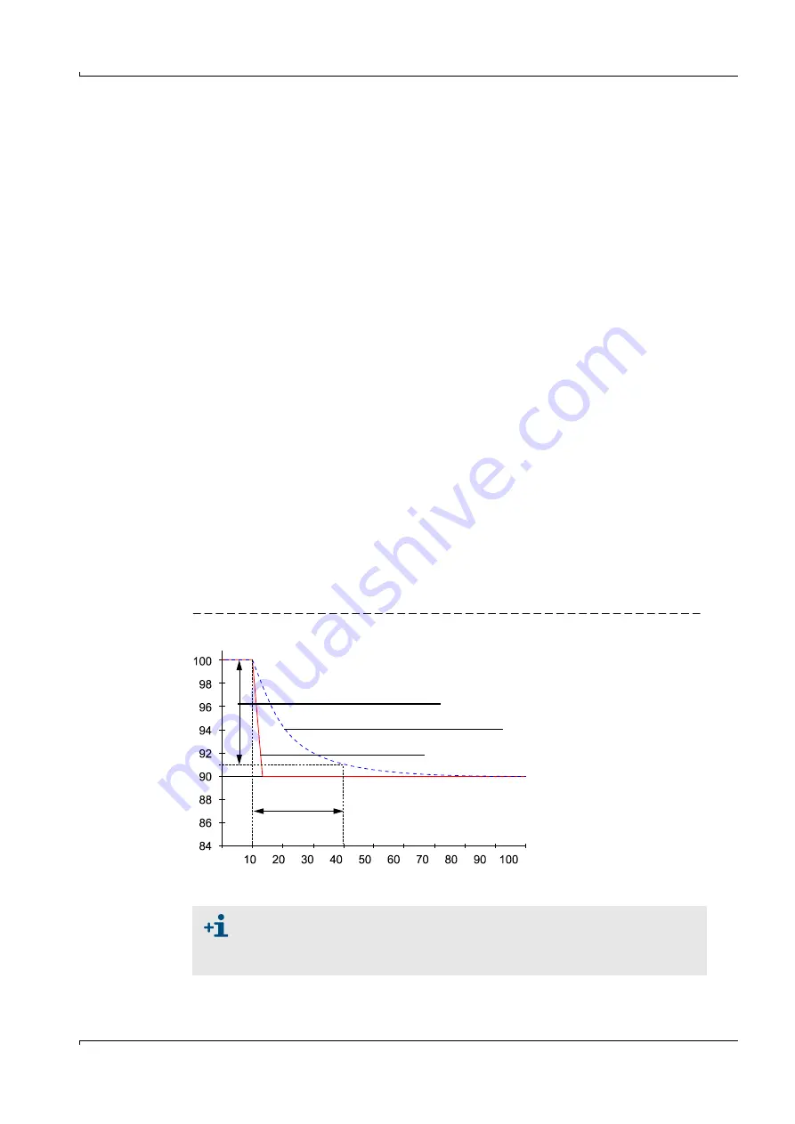
Response time

The response time is the time taken by the measuring device to reach 90% of the end value
after a sudden change in the measured value (

 Fig. 11

).

The response time can be set to any value in the range 1...300 (typical: 60 ... 90 s). Setting
a higher response time provides better attenuation of transient fluctuations in the
measured value and interference to produce a “smoother” output signal.
There is a separate response time for the measurement of flow velocity and air temperature
respectively. 

Fig. 11

Response time

Measured value

90% of the peak

Measured value with response time

Process change

t in s

Response time

The response time should be regarded as a guide value. If the signal quality of 
the ultrasonic pulses is poor, the FLOWSIC200 requires more measured values 
for an output signal of the same accuracy. As a result, the response time is 
higher, within certain limits, than the set time.

Summary of Contents for FLOWSIC200

Page 1: ...O PERATING INSTRU CTIO NS FLOWSIC200 Flow Velocity Monitor Installation Operation Maintenance...

Page 2: ...gener Ring 27 D 01458 Ottendorf Okrilla Germany Phone 49 35 20552410 Fax 49 35 20552450 E mail info pa sick de Original documents The English version 8013271 of this document is an original document o...

Page 3: ...re personal injury or death WARNING Risk or hazardous situation which could result in severe personal injury or death CAUTION Hazard or unsafe practice which could result in less severe or minor injur...

Page 4: ...nit 18 2 2 2 Bracket for sender receiver unit 19 2 2 3 MCU control unit 20 2 2 4 Connection cable 25 2 2 5 Mounting kit 26 2 3 Computations 27 2 3 1 Flow velocity calibration 27 2 3 2 Temperature cali...

Page 5: ...tem to the measuring location 70 4 2 4 Entering system data 71 4 2 5 Setting the check cycle 72 4 2 6 Configuring the analog output 73 4 2 7 Configuring the analog inputs 75 4 2 8 Configuring the limi...

Page 6: ...s 107 6 2 Sender receiver unit 108 6 3 Control unit 109 7 Specification 111 7 1 Technical data 112 7 2 Dimensions Part Nos 113 7 2 1 Sender receiver units 113 7 2 2 Bracket for sender receiver unit 11...

Page 7: ...nformation FLOWSIC200 Operating Instructions 8013271 1CJ9 V2 0 2022 01 SICK Engineering GmbH 7 FLOWSIC200 1 Important information Function of this document Intended use Safety information and protecti...

Page 8: ...rd applications which conform with the technical data specified Additional information and assistance for special applications are available from your SICK representative It is generally recommended t...

Page 9: ...ituation e g network separation firewalls virus protection and patch management 1 5 Intended use Purpose of the device The FLOWSIC200 measuring system is used for non contact measurement of flow veloc...

Page 10: ...he information on the prevention of injuries and damage given therein WARNING Danger through power voltage The FLOWSIC200 measuring system is an item of electrical equipment designed for use in indust...

Page 11: ...manufacturer Do not use damaged components or parts If you do not follow these guidelines the following applies Any warranty by the manufacturer becomes void The FLOWSIC200 can become dangerous The a...

Page 12: ...the operator must ensure The responsible maintenance personnel are at hand at all times and as quickly as possible The maintenance personnel is sufficiently qualified to respond to malfunctions on the...

Page 13: ...escription FLOWSIC200 Operating Instructions 8013271 1CJ9 V2 0 2022 01 SICK Engineering GmbH 13 FLOWSIC200 2 Product description System overview functional principle System components Computations Che...

Page 14: ...r FLSE200 for mounting the sender receiver units on the tunnel wall MCU control unit For control evaluation and output of data of sensors connected via RS485 interface Connection cable Junction box fo...

Page 15: ...e master FLSE junction box Fig 2 Bus connection FLSE200 MCU with one measuring point Fig 3 Bus connection FLSE200 MCU with several measuring points With the bus version up to eight sensors can be conn...

Page 16: ...ies as a result of certain acceleration and braking effects formulas 2 1 and 2 2 The higher the flow velocity and the smaller the angle to the flow direction are the higher the difference in the trans...

Page 17: ...mes to determine the air temperature Simultaneous detection of flow velocity and temperature can be used to warn of icy conditions when the road surface is wet and temperatures are below or around fre...

Page 18: ...ect the ultrasonic transducer from excessive contamination and mechanical damage e g during tunnel cleaning Fig 5 FLSE200 M sender receiver unit Sender receiver unit type FLSE200 M FLSE200 HM FLSE200...

Page 19: ...be aligned with each other with the required accuracy Two hexagonal bolts and dowels serve to fasten the bracket on the tunnel wall or ceiling The brackets are adapted to the respective sender receive...

Page 20: ...inless steel housing Fig 7 MCU control unit options Standard interfaces DISPLAYMODUL relay 3 relay 4 relay 5 BUS S E unit 1 BUS Term Term BUS S E unit 2 relay 1 relay 2 com nc no com nc no com nc no c...

Page 21: ...I CONTROL UNIT POWER FAILURE MAINTENANCE REQUEST INTERFACE MODULE I O MODULE POWER ERROR TxD RxD Plug in slots for optional I O modules Display module option Backplane with terminal connections for wi...

Page 22: ...t module with 4 outputs NO contact contact load 48 V AC DC 0 5 A 3 Interface module Module to pass on measured values system status and service information to higher level control systems optionally f...

Page 23: ...ule 0 4 20 mA 2 per module 0 Without n With n 1 2 1 Optional analog output plug in module 0 4 20 mA 2 per module 0 Without n With n 1 2 1 Optional digital input plug in module 4 inputs per module 0 Wi...

Page 24: ...Wide range power pack 90 250 V AC Wall mounted housing stainless steel 1 4571 painted grey With Display module Without other options Without optional analog inputs With one additional analog module Wi...

Page 25: ...in the scope of delivery The junction boxes must be connected to the MCU control unit using cables provided by the customer information on cable types and wiring p 43 3 3 2 Fig 10 Connection cable T...

Page 26: ...or FLSE200 HM Bracket for FLSE200 H 1 2M8 1 4571 2031891 2x dowel SLM 8N A4 2x hexagon screw 8 55 A4 Stainless steel only Bracket for FLSE200 M Bracket for FLSE200 HM Bracket for FLSE200 H 1 Junction...

Page 27: ...0 can be done by a comparison measurement with a separate temperature sensor e g Pt100 but is generally not necessary since the active measuring distance can be determined extremely accurately 1 cm se...

Page 28: ...25 m s depending on the measuring path and gas temperature In this case check the transducers and electronic components If the signal amplitude or waveform does not match the expected values the tran...

Page 29: ...2 4 3 Check cycle output on the analog output A check cycle is output as follows 90 s zero value live zero 90 s span value The output duration of 90 s is the default factory setting The value can be...

Page 30: ...30 FLOWSIC200 Operating Instructions 8013271 1CJ9 V2 0 2022 01 SICK Engineering GmbH Product description...

Page 31: ...Assembly and installation FLOWSIC200 Operating Instructions 8013271 1CJ9 V2 0 2022 01 SICK Engineering GmbH 31 FLOWSIC200 3 Assembly and installation Project planning Assembly Installation...

Page 32: ...MCU and junction boxes Plan power supply 3 1 2 Requirements for the installation location for the sender receiver units The master and slave sender receiver units must be installed on opposite tunnel...

Page 33: ...direction of travel of the vehicles Fig 13 Correct Incorrect Traffic Traffic Traffic Traffic If due to structural conditions the measurement axis has to be set so low that the maximum permissible vehi...

Page 34: ...art drill hole dimensions Fig 14 Insert anchor bolts mounting kits 2D4 2D8 4D8 1 4571 PA 2M8 1 4571 or anchor bolts mounting kit 2M8 4M8 1 4529 Fasten the brackets with the hexagon head screws or nuts...

Page 35: ...d the MCU must be terminated at both ends with resistors These are already present on the boards jumpers To check change the termination open the MCU and sender receiver units position the jumpers on...

Page 36: ...for hexadecimal addressing from address 1 to 7 Fig 16 To change the address open the sender receiver unit and set the desired address Then close the sender receiver unit again Fig 16 Hardware addressi...

Page 37: ...tically and tilted horizontally over a wide range This allows easy adaptation to local conditions such as the slope of the tunnel wall road inclination curves The two mounting holes in the part of the...

Page 38: ...ion Fig 19 Hanging positioning with connection cable from below Fig 20 Hanging positioning with connection cable from above Reduced swivel range Extended swivel range 90 210 125 245 40 40 70 350 inclu...

Page 39: ...e FLSE200 H FLSE200 HM sender receiver unit 3 2 4 Aligning the sender receiver units After installation the sender receiver units must be aligned so that the respective transmission directions match F...

Page 40: ...gnment with aid string or similar or by sight 2 Fine adjustment with laser pointer or similar 3 2 5 Installing the junction box Install this component on a level surface tunnel wall or roof as shown i...

Page 41: ...mounting kits can be used for fastening p 26 2 2 5 installation p 34 Fig 14 210 350 120 250 340 320 M8 Clearance for cables 160 Clearance for door swing area minimum sideways distance to passing vehi...

Page 42: ...nnected from the power supply Only connect the sender receiver units to the MCU control unit as intended WARNING Hazard through voltage The cables and wires must be permanently installed The plant ope...

Page 43: ...J9 V2 0 2022 01 SICK Engineering GmbH 43 3 3 2 Information on wiring Fig 26 Wiring T es t MCU Tunnel FLSE 200 Slave FLSE200 Master Junction box FLSE200 connection cable SICK scope of delivery Connecti...

Page 44: ...tion box SICK scope of delivery FLSE200 Master connection 2 pairs of wires twisted pair operating capacitance wire wire 110 pF m wire cross section 0 25 mm2 1 pair of wires with wirecross section 1 mm...

Page 45: ...owerful power supply unit Both solutions are available from the manufacturer on request 3 3 3 Connecting sender receiver units and junction boxes These components are to be interconnected as shown in...

Page 46: ...o requirements p 48 Fig 29 p 49 Fig 30 Fig 31 Fig 32 Connect power cable to terminals L1 N PE Fig 27 Close off unused cable ducts with dummy plugs DISPLAYMODUL relay 3 relay 4 relay 5 BUS S E unit 1 B...

Page 47: ...pply voltage 24 V DC RS232 Connection for optional I O module Connections for relays 1 to 5 Connections for S R unit Master Connections for analog inputs 1 and 2 Connection for analog output Connectio...

Page 48: ...85 to Master 4 3 GN YE 6 1 BU RD Assignment plug connector Master RS485 to MCU 4 3 GN YE 6 1 BU RD 5 2 PK GY On site cable to additional measuring points for bus wiring max 8 Operation malfunction Mai...

Page 49: ...t module using on site network cables AO module terminal assignment Fig 30 Analog output module terminal assignment AI module terminal assignment Fig 31 Analog input module terminal assignment DO modu...

Page 50: ...O contacts Assignment 11 AI 1 AO 1 DI 1 n c relay 1 n o relay 1 12 AI 1 AO 1 gnd com relay 1 com relay 1 13 AI 2 AO 2 gnd com relay 2 com relay 3 14 Screen gnd Screen gnd DI 3 n c relay 2 n o relay 3...

Page 51: ...connection for power supply 90 250 V AC1 Terminal connection for customer wiring Function Connection Terminal No Output relay 1 operation malfunction com 1 n c 1 2 n o 2 3 Output relay 2 maintenance...

Page 52: ...h manufacturer Analog input a in 1 25 gnd 26 a in 2 27 gnd 28 Connections for sender receiver unit Master 24 31 36 24 32 37 RS485 A 33 38 RS485 B 34 39 scr 35 40 Input voltage supply 24V DC 3 24 V 41...

Page 53: ...or optional modules Connection is made to terminals 101 180 on the backplane The following shows the I O module connection for slot 1 as an example Connect the I O modules to slots 2 8 in the same man...

Page 54: ...nstallation Digital module connection Fig 37 Digital module on slot 1 101 a 102 b 103 c 104 d 105 a 106 b 107 c 108 d 109 gnd 110 scr 101 a 102 b 103 c 104 d 105 a 106 b 107 c 108 d 109 gnd 110 scr 10...

Page 55: ...200 Operating Instructions 8013271 1CJ9 V2 0 2022 01 SICK Engineering GmbH 55 FLOWSIC200 4 Commissioning and parameterization Basics Standard commissioning procedure Advanced commissioning Operating p...

Page 56: ...tes Laptop PC with Processor At least Pentium III 500 MHz or comparable type USB interface alternative RS232 via adapter Working memory RAM At least 1 GB Operating system MS Windows XP VISTA Windows 7...

Page 57: ...Commissioning and parameterization FLOWSIC200 Operating Instructions 8013271 1CJ9 V2 0 2022 01 SICK Engineering GmbH 57 Fig 38 Installing the USB driver...

Page 58: ...Start the software from the SICK SOPAS start menu The start page is displayed 4 1 3 1 Changing the language If required set the desired language in the Tools Language menu p 58 Fig 39 Confirm the dial...

Page 59: ...ch mode 3 Select device family MCU and click Next Fig 41 Selecting the device family 4 If devices are to be connected via Ethernet configure the IP addresses Click Add NOTICE The MCU P does not suppor...

Page 60: ...Next 6 When devices are connected via serial connections COM ports select the COM ports used and click Next If you are not sure which COM ports are used select all COM ports Fig 43 Selecting COM port...

Page 61: ...g 44 Saving the search settings 4 1 3 3 Connect to the device with advanced mode 1 Click Search settings 2 Select search mode Interface oriented search 3 Select the communication interfaces where the...

Page 62: ...Add Enter the IP address of the device or the IP address range when several devices are used and confirm with OK Select TCP port 2111 in the TCP port directory Define the protocol settings in the Pro...

Page 63: ...ta format in the Format directory according to p 63 Fig 49 Fig 49 Configuring the data format Define the protocol settings in the Protocol directory according to p 61 Fig 45 Define the timeout setting...

Page 64: ...22 01 SICK Engineering GmbH Commissioning and parameterization 4 1 4 Information on using the program Fig 50 Overview 1 Device search 2 Project area 3 Device search progress 4 Device search abort 5 De...

Page 65: ...selection Move the required devices with drag and drop or a double click on the required device into the project area The configuration of the devices is shown in a separate device window The device...

Page 66: ...e parameter values which can be written at the currently logged in user level are downloaded Login Opens the login dialog Logout Logs out the user from the device Import Imports a suitable device from...

Page 67: ...y out the following procedure Connect the measuring system to the SOPAS ET program scan the network and add the required device file MCU FLOWSIC200 M FLOWSIC200 H FLOWSIC200 H M to the current project...

Page 68: ...eral devices are delivered at the same time or when the MCU is swapped later The following steps are then necessary Select device file MCU open directory Configuration Application Selection p 68 Fig 5...

Page 69: ...ctivating connected sender receiver units For correct communication of the MCU with all connected sender receiver units these must be activated in the Configuration System Configuration directory in t...

Page 70: ...tory Configuration Application Selection p 68 Fig 55 set the measuring system to Maintenance p 67 4 2 and enter the Level 1 password p 64 4 1 4 Open device file FLOWSIC200 M or FLOWSIC200 H or FLOWSIC...

Page 71: ...it in Maintenance and enter the Level 1 password p 64 4 1 4 Select directory Configuration Application Parameters p 70 Fig 57 In field Installation Parameters p 70 Fig 57 enter the path length and ins...

Page 72: ...or the automatic control cycle open the MCU device file and select directory Adjustment Function Check Automatic Fig 59 Directory Adjustment Function Check Automatic settings example Entry field Param...

Page 73: ...le for settings Field Parameter Remark Error Current Value Live Zero LZ or 20 mA mA value to be output in Malfunction state error case size depends on connected evaluation system Output Error current...

Page 74: ...value 3 Sound velocity Measured value 4 Acoustic temperature Measured value 5 Temperature A Measured value 6 Temperature B Measured value 7 Signal to noise ratio A Measured value 8 Signal to noise rat...

Page 75: ...may only be changed by SICK Service Field Parameter Remark Aim value in the MCU measurement block Measured value 1 to 8 Variable to be assigned to the selected analog input Range low Lower measuring r...

Page 76: ...low velocity Measured value 3 Sound velocity Measured value 4 Acoustic temperature Measured value 5 Temperature A Measured value 6 Temperature B Measured value 7 Signal to noise ratio A Measured value...

Page 77: ...Value Damping to set the response time Fig 64 Directory Configuration Value Damping display for a connected sender receiver unit Field Parameter Remark Damping time for Sensor 1 Value in s Response ti...

Page 78: ...d with the limit value relay p 76 4 2 8 Example Measuring range 20 20 m s The Live zero value lower end value corresponds to a physical value of 20 m s the 20 mA value upper end value corresponds to a...

Page 79: ...essed without a device connected and transferred to the device again later Saving as a protocol Device data and parameters are registered in the Parameter protocol A Diagnosis protocol can be created...

Page 80: ...device and update device data by selecting Parameters Read from device in the menu Fig 67 Updating device data Select directory Diagnosis Protocols and click the desired protocol type Fig 68 Directory...

Page 81: ...ocol Fig 70 Parameter protocol example 345 6 7 345 8 1 E 0 1 2 34 1 35 1 1 0 6 7 1 2 34 6 8 1 35 6 9 1 4 1 4 8 1 8 5 5 4 0 1 A 8 8 A 8 4 0 A A 5 5 5 B 5 8 B 6 9 C D 6 8 6 1 8 4 6 1 8 4 6 1 8 4 6 35 4...

Page 82: ...k Set State Fig 71 Setting the operational state Checking the signal waveform Checking the signal waveform allows an assessment on the quality of the received ultrasonic signals For display on the scr...

Page 83: ...arameterization FLOWSIC200 Operating Instructions 8013271 1CJ9 V2 0 2022 01 SICK Engineering GmbH 83 Type FLSE200 M Fig 72 Burst waveform HF signal unconditioned signal Fig 73 Burst waveform demodulat...

Page 84: ...structions 8013271 1CJ9 V2 0 2022 01 SICK Engineering GmbH Commissioning and parameterization Type FLSE200 H and FLSE200 HM Fig 74 Burst waveform HF signal unconditioned signal Fig 75 Burst waveform d...

Page 85: ...is open the MCU device file select the Configuration System Configuration directory and check whether the number of outputs entered in the Number of external I O field matches the existing ones correc...

Page 86: ...uration I O Configuration Digital Output Digital outputs directory Field Parameter Remark Inverted Inactive Define the switching direction Active Source bit Bit 0 Malfunction Bit 1 Maintenance Bit 2 M...

Page 87: ...us of each relay is shown in the Diagnosis I O Diagnosis Digital Outputs directory Fig 78 Diagnosis I O Diagnosis Digital Outputs directory To check whether relays switch as intended measured values w...

Page 88: ...GmbH Commissioning and parameterization 4 3 1 3 Assigning and configuring limit value switches to optional digital outputs Select the Configuration Limit Values Switches directory for assigning Config...

Page 89: ...ce file MCU set the measuring system to Maintenance mode and enter the Level 1 password p 64 4 1 4 Switch to the Configuration System Configuration directory The field Interface Module shows the insta...

Page 90: ...and enter the new address in field Fieldbus address field Profibus DP Configuration Fig 81 Directory Configuration I O Configuration Interface Module NOTICE Query via Interface Profibus When connecti...

Page 91: ...y when the address is available when the device is ordered If not standard address 192 168 0 10 is entered The following steps are necessary to change the address Set the desired network configuration...

Page 92: ...h and sound velocity of the real gas under standard conditions p 16 2 1 3 Exact acoustic temperature measurement is only possible when the sound velocity of the real gas remains constant at a referenc...

Page 93: ...M and set the measuring system to Maintenance p 67 4 2 The miniature switch must be set to address 0 p 36 Fig 16 Fig 83 Configuration Device Parameters directory NOTICE For bus systems it must be ensu...

Page 94: ...start can be set from MCU firmware 01 16 00 or higher 3 Open the project Fig 84 Login entry 4 Login with user level Service 5 Switch to Maintenance mode Fig 85 System Configuration menu item 6 Select...

Page 95: ...Diag Display diagnostic information warnings and errors during a start using the Main menu sensor information during a start using the Diagnostics menu p 96 Fig 88 This function is only active when w...

Page 96: ...guring 4 4 3 1 MCU Analog outputs inputs Set the MCU to Maintenance mode and select the I O Parameter submenu Select the desired parameter and enter the default password 1234 using scrolls from 0 to 9...

Page 97: ...para ao Back Enter Back Enter Back Save Back Save Back Save Back Save Back Save Back Save Back Save Back Save 1 2 Limit Low Limit High 1 2 Limit Low Limit High 0000 00 0000 00 0000 00 0000 00 0100 00...

Page 98: ...ith buttons and or and write to the device with Save confirm twice Fig 90 Menu structure for parameterization Back Enter 1 Path length 2 Installation angle 3 Cross Section Area Parameter param sensor...

Page 99: ...4 2 6 Section Selection field Significance Common Display Settings Display language Language version shown on the LC display Display Unit System Unit system used in displays Overview Screen Settings B...

Page 100: ...100 FLOWSIC200 Operating Instructions 8013271 1CJ9 V2 0 2022 01 SICK Engineering GmbH Commissioning and parameterization...

Page 101: ...Maintenance FLOWSIC200 Operating Instructions 8013271 1CJ9 V2 0 2022 01 SICK Engineering GmbH 101 FLOWSIC200 5 Maintenance General Measures to be taken when cleaning the tunnel...

Page 102: ...tenance intervals are more than 24 weeks For FLOWSIC200 with sender receiver units FLSE200 H and FLSE200 HM maintenance cycles of up to 5 years are possible when used according to specifications The w...

Page 103: ...vent water from reaching the ultrasonic transducers Safe protection is ensured by covering the protective tubes with the supplied caps No protective measures are required for the FLSE200 H and FLSE200...

Page 104: ...104 FLOWSIC200 Operating Instructions 8013271 1CJ9 V2 0 2022 01 SICK Engineering GmbH Maintenance...

Page 105: ...Malfunctions FLOWSIC200 Operating Instructions 8013271 1CJ9 V2 0 2022 01 SICK Engineering GmbH 105 FLOWSIC200 6 Malfunctions General information Implausible measured values Malfunctions...

Page 106: ...device file FLOWSIC200 M FLOWSIC200 H FLOWSIC200 H M or MCU p 58 4 1 3 and p 64 4 1 4 Move the mouse pointer to the respective message to display more details on the significance of individual message...

Page 107: ...s measuring distance influenced by high vehicles Check installation situation p 32 3 1 1 Contact SICK Service Symptom Possible cause Action No indication on LC display of control unit option No supply...

Page 108: ...sible causes and correction Display SOPAS ET Possible cause Action Communication A B Connection cable not connected correctly Cables used do not comply with required specification Both sender receiver...

Page 109: ...ion No supply voltage Fuse defective Check voltage supply Contact SICK Service Description Display Message Significance Possible cause Action AO configuration Number of analog outputs configured and n...

Page 110: ...ted Sensor failure Communication problems on RS485 line Check sensor addressing and availability p 110 Fig 95 Correct sensor selection p 85 Fig 76 Contact SICK Service Interface module No communicatio...

Page 111: ...uctions 8013271 1CJ9 V2 0 2022 01 SICK Engineering GmbH 111 FLOWSIC200 7 Specification Technical data Dimensions Part Nos Connection cable sender receiver unit junction box Accessories Options Consuma...

Page 112: ...2 Output signals Analog output 0 2 4 22 mA max load 750 resolution 0 01 mA further analog outputs with I O modules option Digital outputs 5 potential free outputs NC contacts for status signals opera...

Page 113: ...V2 0 2022 01 SICK Engineering GmbH 113 7 2 Dimensions Part Nos All dimensions are in mm 7 2 1 Sender receiver units FLSE200 M Fig 96 FLSE200 M sender receiver unit 120 150 34 60 45 60 80 40 Designati...

Page 114: ...2022 01 SICK Engineering GmbH Specification FLSE200 H FLSE200 HM Fig 97 FLSE200 H FLSE200 HM sender receiver unit 150 60 150 83 60 L 150 60 Component Dimension L Part No FLSE200 HM sender receiver uni...

Page 115: ...cket for FLSE200 M Bracket for FLSE200 H FLSE200 HM Fig 99 Bracket for FLSE200 H FLSE200 HM 60 9 26 77 40 A A M 8 A A Designation Part No Bracket for FLSE200 M 7042039 Bracket for FLSE 200 M material...

Page 116: ...control unit in 19 slot shown with Display module option 340 320 300 125 210 160 Designation Part No Control unit MCU NWSN 1046298 Control unit MCU N2SN 1046299 Control unit MCU NWSD 1046113 Control u...

Page 117: ...nction box In aluminium housing Fig 102 Junction box In stainless steel housing Fig 103 Junction box in stainless steel housing Mounting holes 113 80 52 57 10 125 4 8 Designation Part No Junction box...

Page 118: ...trically isolated 80 V difference 2034656 Analog output module 2 channels 500 0 4 22 mA electrically isolated per module 2034657 Digital output module 2 channels as NC contact 2034659 Digital output m...

Page 119: ...1CJ9 V2 0 2022 01 SICK Engineering GmbH 119 7 4 2 Miscellaneous 7 5 Consumable parts for 2 years operation Designation Part No Hook spanner 7042115 DME 2000 distance sensor 1010578 Designation Quanti...

Page 120: ...nsumfanges wird das Passwort ben tigt Falls zur Eingabe eine falsche Taste gedr ckt wird mu das Fenster geschlossen und anschlie end die Passworteingabe wiederholt werden Password Authorized Client Af...

Page 121: ...Specification FLOWSIC200 Operating Instructions 8013271 1CJ9 V2 0 2022 01 SICK Engineering GmbH 121...

Page 122: ...8080 7425 E Mail enquiry my sick com Mexico Phone 52 472 748 9451 E Mail mexico sick com Netherlands Phone 31 0 30 229 25 44 E Mail info sick nl New Zealand Phone 64 9 415 0459 0800 222 278 tollfree...

Reviews: