Chapter
5
Operating Instructions
CLV 45x Bar Code Scanner
5-6
©
SICK AG · Division Auto Ident · Germany · All rights reserved
8 009 139/K949/06-06-2002
Electrical installation
The connection of the host interface via the AMV/S 40 connection module is described in
the
operating instructions "AMV/S 40 connection module"
(Order No. 8 008 292, English
edition).
Termination of the RS-422 type
The termination can be carried out in the AMV/S 40 connection module.
Refer to the
Operating instructions "AMV/S 40 connection module ".
Connection to the CL 20 mA interface
In order to connect the RS-422 type to a CL 20 mA interface you can use the optional
interface converter No. 2 020 825 for installation in the AMV/S 40 connection module. The
wiring is described in the operating instructions
"AMV/S 40 connection module "
.
Activating the RS-232 type
The RS-232 type can be activated by means of the CLV-Setup user interface:
1.
Select the H
OST
INTERFACE
tab card.
2.
Select the "RS-232" option in the "H
ARDWARE
" list field in the "D
ATA
FORMAT
" section.
3.
Carry out the download to the CLV. To do so, click on
in the toolbar.
The D
OWNLOAD
PARAMETERS
dialog box is opened.
4.
Confirm the dialog box with the saving option P
ERMANENT
.
The CLV operates the host interface in the RS-232 type.
HINT
The communication parameters can be changed if required via the H
OST
INTERFACE
configu-
ration tab.
To do so, edit the D
ATA
FORMAT
and I
NTERFACE
PROTOCOL
sections.
5.5.5
Connecting the CAN interface
Instructions for the connection and for configuration of the CLV to use the device in the
SICK-specific CAN Scanner Network or in a CANopen network see the
operating instructions
“Application of the CAN interface“
(no. 8 009 180, English edition)
5.5.6
Connecting the PC
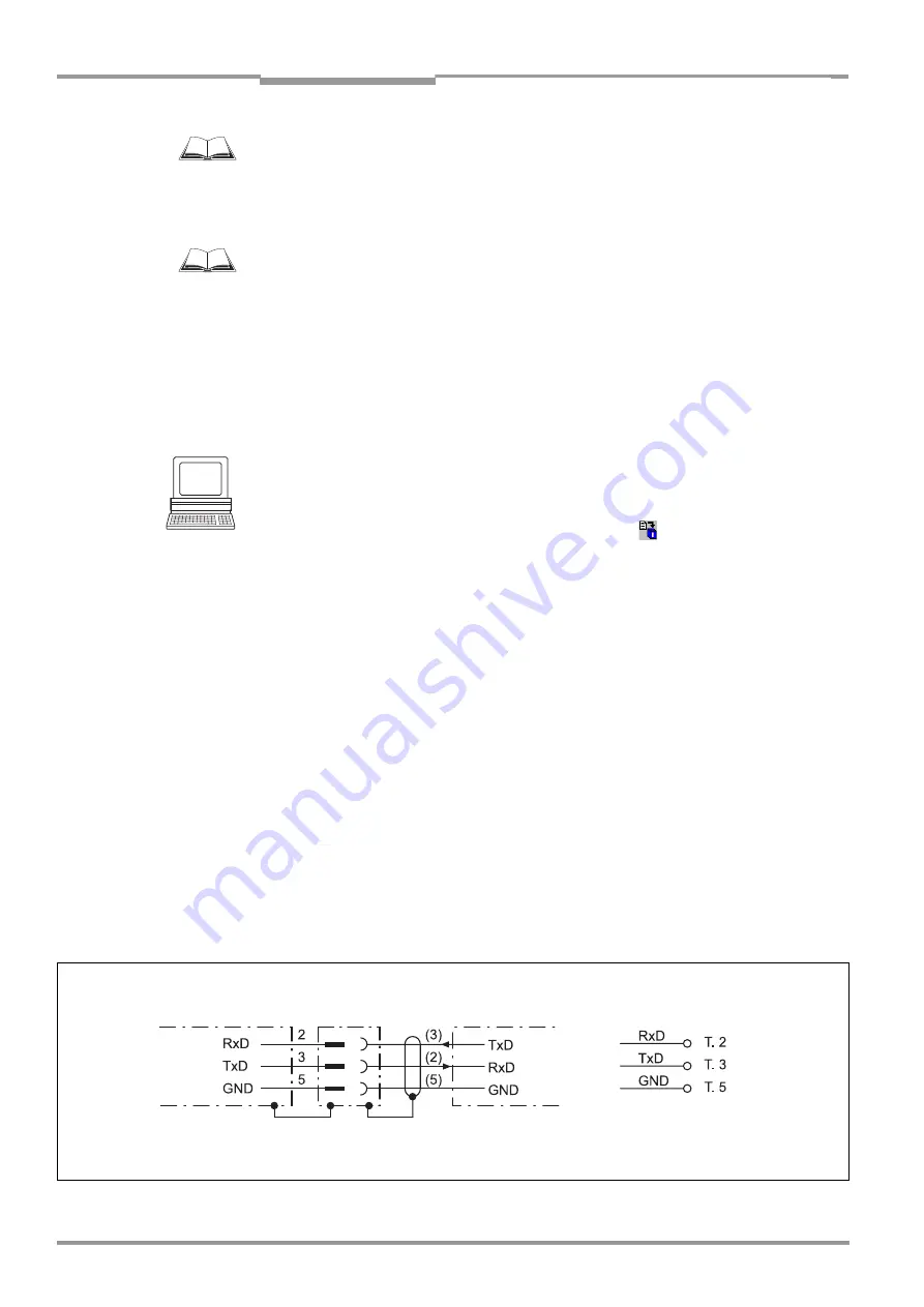
The CLV is operated and configured with the "CLV-Setup" software. To this purpose it must
be connected to the PC via the terminal interface (auxiliary data interface). In contrast to
the host interface the terminal interface has a data format which cannot be modified and a
fixed data transmission rate.
shows the wiring of the terminal interface. The cable
length should not exceed 10 m.
Fig. 5-3:
Wiring the terminal interface
RS-232
( ) = 9-pin D-Sub
connector at PC
or 9-pin
connector "Service"
Terminal assignment
AMV 40-011/AMS 40-012, -013:
CLV 45x
PC


