


Chapter
4
Operating Instructions
CLP 100 Bar Code Reader
Installation
14
©
SICK AG · Division Auto Ident · Germany · All rights reserved
8 008 912/0000/21-08-2002
4.3.2
Adjusting the CLP 100
The adjusting operating mode supports the adjustment of the CLP 100. In this operating
mode the green LED extinguishes if the reading process fails ("No Read"). If the green LED
does not light up, the CLP 100 cannot read the bar code. If the green LED flickers, the CLP
100 can only read the bar code badly. If the green LED shows steady light, the CLP 100 is
aligned optimally. The scanning frequency in adjusting mode amounts to 500 Hz.
1.
Connect the CLP 100 to the supply voltage and switch on the supply voltage.
2.
Connect the CLP 100 to the PC.
3.
Call up the CLP Setup user interface (
refer to Section 10.2, Page 33
).
4.
In the CLP Setup select the D
EVICE
CONFIGURATION
tab card.
5.
Click in the O
PERATING
MODE
field and select A
DJUSTING
MODE
.
6.
Click in the LED
DISPLAY
field and select N
O
R
EAD
/G
OOD
R
EAD
.
7.
Carry out the download to the CLP 100 (
refer to Section 6.5.1, Page 21
).
8.
Guide objects with bar codes realistically into the reading area of the CLP 100. Ensure
that the permitted reading angle is not exceeded.
9.
Start the reading pulse: Cover the optical path of the sensor or make connection (
refer
to Section 4.4
10. Align the CLP 100 so that the green LED lights up steadily as far as possible (reading
result "Good Read").
11. Tighten the screws.
The CLP 100 is aligned optimally to the bar code.
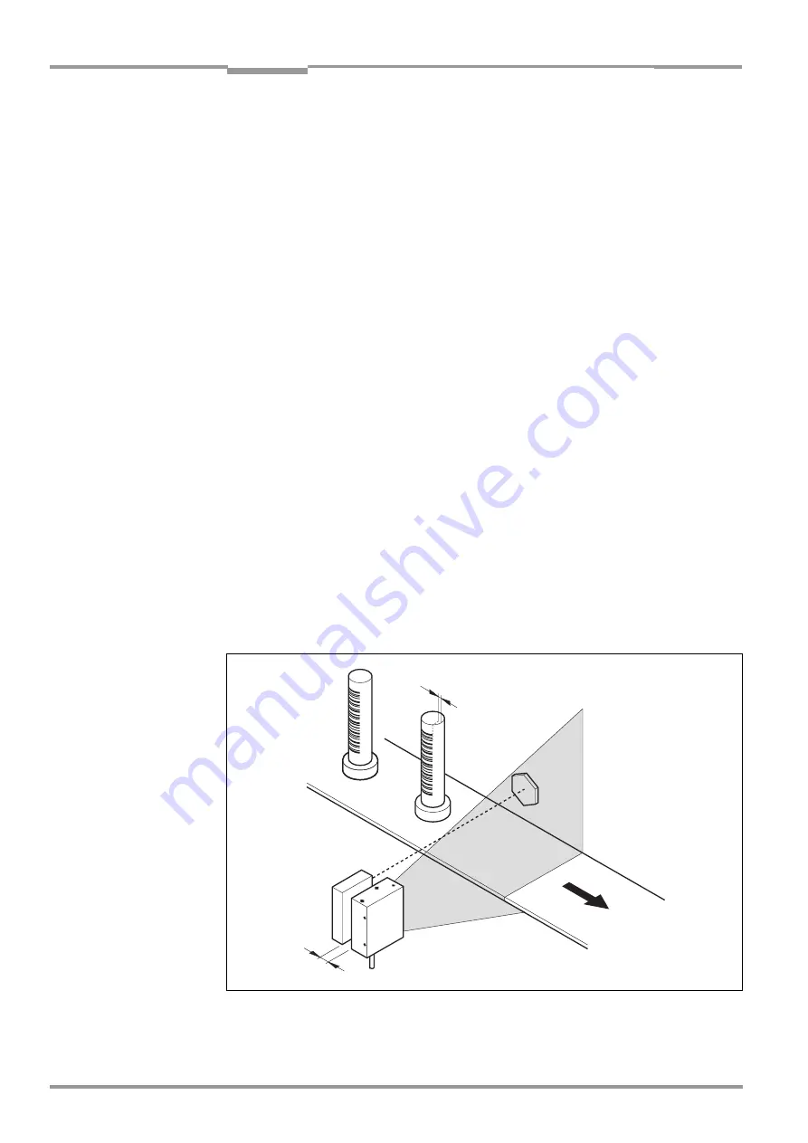
4.4
Installing the reading-pulse sensor
If the CLP 100 is triggered via an external sensor, the sensor and a reflector have to be
installed near the CLP 100.
Figure 4-7
shows an example of the installation site of the
sensor.
Fig. 4-7:
Installation site for the reading-pulse sensor and the reflector (b smaller than a)
a
b


