background image

ITALIANO

ENGLISH

SBM 155

22

COD. 655632  Rev.0

ISTRUZIONI PER L’USO

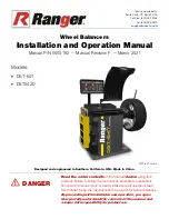
PANNELLO COMANDI - LEGENDA

1. Visualizzatore dati
2. Diodi luminosi di direzione punto di squilibrio
3. Punto di squilibrio (LED)
4. TastI impostazione distanza cerchio
5. TastI impostazione diametro cerchio
6. TastI impostazione larghezza cerchio
7. Tasto selezione unità di misura per larghezza o diametro cerchio (mm/inch)
8. Tasto selezione programma di equilibratura (MODE)
9. Tasto selezione utente
10. Tasti incremento / decremento dati
11. Tasto conferma dato
12. Tasto ottimizzazione
13. Tasto SPLIT
14. Tasto funzioni di controllo (MENÙ)
15. Indicatori selezione utente
16. Indicatore selezione programma pax
17. Indicatori selezione programma di equilibratura
18. Indicatori selezione programma di ottimizzazione
19. Indicatori selezione programma di separazione pesi
20. Indicatore selezione misura distanza
21. Indicatore selezione misura larghezza
22. Indicatore selezione misura diametro
23. Indicatore selezione unità di misura
24. Tasto START
25. Tasto STOP

» Quando la rotazione non è effettuata tramite il motore elettrico, premendo

il pedale verso il basso si  blocca la rotazione della ruota.

» Per azionare il sistema pneumatico di bloccaggio / sbloccaggio  flangia

tirare il pedale verso l’alto (fig.17).

» per acquisire le posizioni dei pesi da applicare con il calibro ALUDATA

tirare il pedale verso l’alto (fig.17).

17

INSTRUCTIONS FOR USE

CONTROL PANEL - KEY

1. Data display
2. Luminous diode imbalance direction indicators
3. Imbalance point (LED)
4. Rim distance setting buttons
5. Rim diameter setting buttons
6. Rim width setting buttons
7. Unit of measurement selection button for rim width or diameter (mm/inch)
8. Balancing program selection button (MODE)
9. Select user button
10. Data increase/decrease buttons
11. Data confirm button
12. Optimization button
13. SPLIT button
14. Control functions button (MENU)
15. User selection indicators
16. Pax program selection indicator
17. Balancing program selection indicators
18. Optimization program selection indicators
19. Weight separation program indicators
20. Distance measurement selection indicator
21. Width measurement selection indicator
22. Diameter measurement selection indicator
23.  Unit of measurement selection indicator
24. START button
25. STOP button

» When the wheel is not being driven by the electrical motor, pressing

the brake pedal locks the rotation of the wheel.

» In order to activate the pneumatic adapter /locking/unlocking system

push the pedal up (fig.17).

» To read the positions for weight application with the ALUDATA gauge,

push the pedal up (fig.17).

18

Summary of Contents for SBM 155

Page 1: ...HINWEISE MANUAL DE INSTRUCCIONES ÐÓÊÎÂÎÄÑÒÂÎ ÏÎ ÝÊÑÏËÓÀÒÀÖÈÈ WHEEL BALANCER EQUILIBREUSE AUSWUCHTMASCHINE EQUILIBRADORA ÁÀËÀÍÑÈÐÎÂÎ ÍÛÉ ÑÒÀÍÎÊ SBM 155 CSI I UK F D ES COD 655632 Rev 0 T T T T Tyr yr yr yr yres Equipment es Equipment es Equipment es Equipment es Equipment T T T T Tools ools ools ools ools ...

Page 2: ...oneous or unacceptable use This symbol is used in the present manual to warn the operator of particular risks associated with the use of the machine CONTENTS GENERAL WARNINGS AND CONTENTS 2 MAIN COMPONENT PARTS 4 TECHNICAL CHARACTERISTICS 4 ACCESSORIES Provided and on request 6 UNPACKING AND LOCATION 8 INSTALLATION Electrical connection 10 Fitting the adapter 12 TROUBLE SHOOTING FAULTS 17 INSTRUCT...

Page 3: ... llamar la atención del operador sobre particulares riesgos relacionados con el uso de la máquina ÍNDICE ÍNDICE Y ADVERTENCIAS GENERALES 3 PARTES Y COMPONENTES PRINCIPALES 5 CARACTERÍSTICAS TÉCNICAS 5 ACCESORIOS de serie y bajo pedido 7 DESEMBALAJE Y COLOCACIÓN 9 INSTALACIÓN Conexión eléctrica 11 Instalación de las bridas 13 MAL FUNCIONAMIENTO SUS CAUSAS Y POSIBLES SOLUCCIONES 20 INSTRUCCIONES PAR...

Page 4: ...ni di emergenza carter di protezione ruota quando il carter è aperto un dispositivo elettrico impedisce l avviamento della macchina Possibilità di memorizzare dati di lavoro di due utenti che lavorano contemporaneamente In funzione del modello la macchina è dotata di questi dispositivi ILLUSTRATIVE MACHINE DRAWING indicating the main parts relevant to use KEY A MAIN SWITCH B POWER SUPPLY CABLE C W...

Page 5: ... ESQUEMA ILUSTRATIVO DE LA MÁQUINA con indicación de las principales partes componentes para el uso LEYENDA A INTERRUPTOR GENERAL B CABLE DE ALIMENTACIÓN C TABLERO PORTAPESOS D PANEL DE MANDOS E CÁRTER DE PROTECCIÓN DE LA RUEDA F BRIDA G CALIBRES AUTOMÁTICOS H PEDAL DE FRENO I SOPORTE DE LA BRIDA Y ACCESORIOS L ALIMENTACIÓN NEUMÁTICA CARACTERÍSTICAS TÉCNICAS Equilibradora electrónica de lanzamient...

Page 6: ...adi Rapidi 3 Flangia per Ruote Moto 4 Distanziale 5 III e IV Cono 6 Anello Centraggio Renault Citroen Peugeot DATI DI TARGA REGISTRATION PLATE DATA DONNEES DE PLAQUE ANGABEN AUF DEM MATRIKELSCHILD DATOS DE CHAPA ÄÀÍÍÛÅ ÒÀÁËÈ ÊÈ 3 4 1 3 4 2 1 2 6 5 4 3 2 TECHNICAL DATA DIMENSIONS Max height with cover open 1800mm Depth with cover open 1260mm Width without adapter 860mm Width with adapter 900mm WEIG...

Page 7: ...3 Plateau pour les roues de moto 4 Entretoise 5 IIIe et IVe Cône 6 Bague de centrage Renault Citroën Peugeot DATOS TÉCNICOS MEDIDAS Altura Máx con cárter abierto 1800mm Profundidad con cárter abierto 1250mm Anchura sin brida 860mm Anchura con brida 900mm PESO Peso neto 158 kg Peso bruto 187 Kg ALIMENTACIÓN ELÉCTRICA Alimentación 3 modelos 115V 1 60Hz 230V 1 50Hz 230V 1 60Hz Potencia 0 7 kW Fases 1...

Page 8: ...reti circostanti fig 6 PRESCRIZIONI DI FISSAGGIO Il basamento della macchina è provvisto di 3 fori per il fissaggio al pavimento Un buon fissaggio è indispensabile per avere indicazioni precise e costanti 6 UNPACKING After removing the packing strapping seals cardboard and the pallet see fig 5 check the machine for missing or damaged parts If in doubt do not use the machine and refer to profession...

Page 9: ...a base de la machine est munie de 3 trous pour la fixation au sol Une bonne fixation est indispensable pour obtenir des indications précises et constantes DESEMBALAJE Después de haber retirado el embalaje ver fig 5 asegurarse de la integridad de la máquina controlando que no haya partes visiblemente dañadas En caso de duda no utilizar la máquina y dirigirse a per sonal profesionalmente cualificado...

Page 10: ...hetta scarica elettrica cod N 100789 Nel caso di smarrimento o deterioramento dell etichetta adesiva si prega di richiederla attraverso il relativo numero di codice al servizio parti di ricambio SICAM INSTALLATION ELECTRICAL CONNECTION ANY WORK DONE ON THE ELECTRICAL SYSTEM EVEN A SIMPLE JOB MUST ONLY BE DONE BY QUALIFIED PROFES SIONAL TECHNICIANS Check the mains voltage is conform to that indicat...

Page 11: ...AM indicando el correspondiente número de código ÓÑÒÀÍÎÂÊÀ ÏÎÄÑÎÅÄÈÍÅÍÈÅ ÝËÅÊÒÐÈ ÅÑÒÂÀ ËÞÁÛÅ ÐÀÁÎÒÛ Ñ ÝËÅÊÒÐÈ ÅÑÊÈÌ ØÊÀÔÎÌ ÄÀÆÅ ÍÅÇÍÀ ÈÒÅËÜÍÛÕ ÎÁÚÅÌÎÂ ÄÎËÆÍÛ ÂÛÏÎËÍßÒÜÑß ÊÂÀËÈÔÈÖÈÐÎÂÀÍÍÛÌ ÏÐÎÔÅÑÑÈÎÍÀËÜÍÛÌ ÏÅÐÑÎÍÀËÎÌ Ïðîâåðèòü ñîîòâåòñòâèå íàïðÿæåíèÿ ëèíèè íàïðÿæåíèþ óêàçàííîìó íà òàáëè êå íà ìàøèíå Ïîäñîåäèíèòü êàáåëü ýëåêòðîïèòàíèå ðèñ 8 A ê âèëêå ñîîòâåòñòâóþùåé åâðîïåéñêèì íîðìàì èëè íîðìàì äåé...

Page 12: ...ruota d automobile utilizzando la flangia univer sale 3 4 5 fori SERRAGGIO RUOTA MOTOCICLO La fig 11 mostra il sistema di serraggio ruota motociclo utilizzando la flangia moto 9a 10c 10a 9b 10b 9c 11 FITTING ADAPTERS Before fitting adapters to the machine it is advisable to clean the machine shaft cone and the hole in the adapter itself A badly fitted adapter will compromise the accuracy of balanc...

Page 13: ...DERN Abb 11 zeigt das Befestigungssystem für Motorradräder mit Hilfe eines Motorradflanschs INSTALACIÓN DE LA BRIDA Antes de fijar la BRIDA a la máquina es oportuno limpiar el cono del árbol de la máquina y el agujero de la BRIDA Una mala adaptación de la BRIDA al árbol influirá en la precisión del equilibrado MONTAJE DE LAS BRIDAS Antes de fijar las bridas a la máquina es oportuno limpiar el cono...

Page 14: ...l sistema di serraggio ruota d automobile utilizzando la flangia universale 3 4 5 fori SERRAGGIO RUOTA MOTOCICLO La fig 15 mostrano il sistema di serraggio ruota motociclo utilizzando la flangia moto 12a 13 12b 14a 14b FITTING THE PNEUMATIC ADAPTER Before fixing the adapter on the machine the machine shaft cone and the adapter hole should be cleaned A poor adapter shaft fastening will nega tively ...

Page 15: ...n actionnant la pédale vers le haut La fig 14b montre le système de serrage des roues de tourisme en utilisant le plateau universel de 3 4 5 trous SERRAGE DE LA ROUE DE MOTO La fig 15 montre le système de serrage de la roue de moto en utilisant le plateau à moto INSTALACIÓN DE LA BRIDA NEUMÁTICA Antes de fijar la BRIDA a la máquina es oportuno limpiar el cono del árbol de la máquina y el agujero d...

Page 16: ...di sinistra non è stato collegato correttamente o è difettoso oppure il cavo è interrotto 1 Controllare il collegamento ed eventualmente sostituire il pick up di sinistra Err 9 Alla fine del secondo lancio di taratura con la ruota sul display compare Err 9 1 Il pick up di destra non è stato collegato correttamente o è difettoso oppure il cavo è interrotto 1 Controllare il collegamento ed eventualm...

Page 17: ...ck up has not been correctly connected or is defective or the cable is disconnected 1 Check left pick up connection and replace if necessary Err 9 At end of second calibrating run with the wheel Err 9 appears on the display 1 The right pick up has not been correctly connected or is defective or the cable is disconnected 1 Check right pick up connection and replace if necessary Err 10 During launch...

Page 18: ...pas été branché correctement soit il est défectueux soit le câble est interrompu 1 Contrôler le branchement et éventuellement remplacer le pick up de gauche Err 9 A la fin du deuxième lancer d étalonnage avec la roue l afficheur montre Err 9 1 Le pick up de droite n a pas été branché correctement soit il est défectueux soit le câble est interrompu 1 Contrôler le branchement et éventuellement rempl...

Page 19: ...cht korrekt angeschlossen ist defekt oder das Kabel ist unterbrochen 1 Den Anschluss des linken Pick Ups kontrollieren und dieses eventuell ersetzen Err 9 Am Ende des zweiten Eichstarts mit dem rad zeigt das Display Err 9 1 Der rechte Pick Up wurde nicht korrekt angeschlossen oder ist defekt oder das Kabel ist unterbrochen 1 Den Anschluss des rechten Pick Ups kontrollieren und dieses eventuell ers...

Page 20: ...en la pantalla aparece Err 8 1 El pick up de la izquierda no ha sido conectado correctamente o es defectuoso o el cable está interrumpido 1 Controlar la conexión y eventualmente sustituir el pick up de la izquierda Err 9 Al final del segundo lanzamiento de calibrado con la rueda en la pantalla aparece Err 9 1 El pick up de la derecha no ha sido conectado correctamente o es defectuoso o el cable es...

Page 21: ...ëåå ïîÿâëÿåòñÿ Err 8 1 Ëåâûé pick up ñîåäèíåí íåïðàâèëüíî èëè ïîëîìàí èëè ïðåðâàí ïðîâîä 1 Ïðîâåðèòü ñîåäèíåíèå ëåâîãî äàò èêà pick up è â ñëó àå íåîáõîäèìîñòè çàìåíèòü Err 9 Â êîíöå âòîðîãî çàïóñêà êàëèáðîâêè ñ êîëåñîì íà äèñïëåå ïîÿâëÿåòñÿ Err 9 1 Ïðàâûé pick up ñîåäèíåí íåïðàâèëüíî èëè ïîëîìàí èëè ïðåðâàí ïðîâîä 1 Ïðîâåðèòü ñîåäèíåíèå ïðàâîãî äàò èêà pick up è â ñëó àå íåîáõîäèìîñòè çàìåíèòü Er...

Page 22: ...matico di bloccaggio sbloccaggio flangia tirare il pedale verso l alto fig 17 per acquisire le posizioni dei pesi da applicare con il calibro ALUDATA tirare il pedale verso l alto fig 17 17 INSTRUCTIONS FOR USE CONTROL PANEL KEY 1 Data display 2 Luminous diode imbalance direction indicators 3 Imbalance point LED 4 Rim distance setting buttons 5 Rim diameter setting buttons 6 Rim width setting butt...

Page 23: ...cquérir les positions des masses à appliquer avec la pige ALUDATA tirer la pédale vers le haut fig 17 INSTRUCCIONES PARA EL USO PANEL DE MANDOS LEYENDA 1 Visualizador de datos 2 Diodos luminosos de dirección punto de desequilibrio 3 Punto de desequilibrio LED 4 Teclas de introducción de la distancia de la llanta 5 Teclas de introducción del diámetro de la llanta 6 Teclas de introducción de la anch...

Page 24: ...in a single measuring cycle and they are displayed separately on the two displays When the figures have been established the wheel is automatically braked to a stop The wheel guard must not be opened before the wheel stops The STOP fig 18 button serves to stop the machine immediately in emergencies The scale and position of the imbalances on the two sides of the wheel are measured in a single meas...

Page 25: ...nzamiento de medición y se indican separadamente en los visualizadores Determinados los datos de la medición la rueda se frena automáticamente hasta pararse No se debe abrir la protección de la rueda antes de que se pare La tecla de parada STOP fig 18 tiene la función de bloquear la máquina en caso de emergencia La magnitud y la posición de los desequilibrios de los dos lados de la rueda se determ...

Page 26: ...rchio è pollici Per impostare le misure della ruota in mm occorre premere il tasto MM INCH e inserire le misure in millimetri così come si leggono sulla ruota Il led acceso indica che la misura selezionata è impostata in mm La distanza è sempre impostata in mm led acceso N B per i programmi PAX l unità di misura predefinita per larghezza e diametro cerchio è mm SELECTING BALANCING PROGRAM The use ...

Page 27: ...ta pour les programmes PAX l unité de mesure prédéfinie pour la largeur et le diamètre de la jante est le millimètre SELECCIÓN DEL PROGRAMA DE EQUILIBRADO El uso de distintos tipos de contrapesos para el equilibrado de los diferentes tipos de llantas de acero o de aleación ligera produce diferencias entre las medidas nominales introducidas para la rueda que se desea equilibrar y las medidas efecti...

Page 28: ... espulsore F ved fig 21c N B Per i programmi ALU 3 e la procedura esterna rimane la stessa per l interno fissare il peso a molletta sul bordo cerchio 21a 21c 21b PROGRAMMING AND FITTING ADHESIVE WEIGHTS WITH THE SPECIAL GAUGE FOR ALUMINIUM OR LIGHT ALLOY RIMS GAUGE Fig 21a A GAUGE BASE CURSOR B WEIGHT POSITIONING GAUGE HEAD C OUTSIDE CLAW D SCREW KNOB E SCALE PLATE IN MILLIMETRES F EXTRUDER G INSI...

Page 29: ...ur fixer la masse à pincette sur le bord de la jante PROGRAMACIÓN Y FIJACIÓN DE LOS PESOS ADHESIVOS CON CALIBRE ESPECIAL PARA LLANTAS DE ALUMINIO O DE ALEACIÓN LIGERA CALIBRE Fig 21a A CALIBRE DE CORREDERA BASE B CABEZAL CALIBRE DE POSICIÓN DE LOS PESOS C PINZA EXTERNA D POMO ROSCADO E PLACA MILIMETRADA F EXPULSOR G PINZA INTERNA PARA FIJACIÓN PESO H EMPUÑADURA CON ALOJAMIENTO DE LA PLACA La máqui...

Page 30: ... adesivi seguire le istruzioni alla pag precedente della procedura Programmazione e fissaggio pesi adesivi con calibro speciale Per ritornare alla visualizzazione del peso singolo basta premere di nuovo il tasto SPLIT 13 fig 18 WEIGHT SEPARATION PROGRAM For aluminum and light alloy rims ALU 2 ALU 3 wheel balancing programs The purpose of the weight separation program is to allow the adhesive imbal...

Page 31: ...che SPLIT 13 fig 18 PROGRAMA DE SEPARACIÓN DE LOS PESOS Para llantas de aluminio o de aleación ligera programas de equilibrado ALU 2 y ALU 3 El programa de separación de los pesos sirve para esconder los eventuales pesos adhesivos de corrección del desequilibrio detrás de los radios de la llanta en caso de que al final de un lanzamiento de equilibrado el peso externo resulte en posición visible es...

Page 32: ... display current static imbalance reading for the wheel Left display minimal residual imbalance that can be achieved by applying the recommended imbalance reduction Displaying these figures is useful for deciding if it is worth continuing the imbalance reduction procedure for the same reason also after the first cycle the STOP button can be pressed to view the static imbalance on the right display...

Page 33: ...de desequilibrio aconsejada Visualizar estos valores es útil para decidir si es conveniente proseguir en la operación de reducción del desequilibrio por el mismo motivo también después del primer lanzamiento es posible pulsando la tecla STOP visualizar en la pantalla de la derecha el desequilibrio estático de la rueda para verificar si es efectivamente útil realizar la operación de reducción Fase ...

Page 34: ... 10 fig 18 The possible settings are GrA display imbalance figures in grams oun display imbalance figures in ounces Press the OK MENU button to move on to the next parameter Sound signal the left display reads Snd and the right display gives the current state enabled or disabled of the sound signal To change the setting use the buttons 10 fig 18 The possible settings are on sound signal enabled oF...

Page 35: ...esequilibrio en gramos oun visualización valor del desequilibrio en onzas Para pasar al parámetro siguiente pulsar la tecla OK MENÚ señal acústica la pantalla de la izquierda visualiza Snd y la de la derecha visualiza el estado de activación o desactivación de la señal acústica para introducir un nuevo valor utilizar las teclas 10 fig 18 los valores posibles son on señal acústica activa oFF señal ...

Page 36: ...otto l albero principale il display visualizza C 5 ed il valore dell angolo di calibrazione 10 tenendo la ruota in questa posizione premere il tasto SPLIT che presenta entrambi i led accesi La taratura eseguita viene automaticamente memorizzata in modo permanente BASIC MACHINE CALIBRATION Press and hold down the MENU button As soon as the left display reads CAL immediately release the button and p...

Page 37: ...de 1 5 seg la tecla MM INCH Ahora la pantalla de la izquierda muestra el mensaje C 1 La tecla MENÚ permite ahora navegar por los diversos menús de regulación y da la posibilidad de elegir entre efectuar la corrección del desequilibrio del árbol la autoregulación de la equilibradora y el reglaje de los calibres automáticos Primera fase de calibrado corrección del desequilibrio árbol Primera fase de...

Page 38: ...BRATING THE AUTOMATIC GAUGES The presence of this device depends on the machine model The calibration of the automatic gauges can be accessed after carrying out the first calibration procedure or using the MENU button in the calibration menu The left display reads d 1 Move the millimeter scale distance cursor B to its retracted position Set the number read on the millimeter scale with the buttons ...

Page 39: ... de equilibrado Si en este lanzamiento de prueba se detecta un desequilibrio elevado es necesario controlar el desgaste los juegos y la suciedad de las partes empleadas para centrar la rueda REGLAJE DE LOS CALIBRES AUTOMÁTICOS La máquina estará dotada o no de estos dispositivos en función del modelo Se puede acceder al reglaje del calibre automático después de efectuar la primera fase de calibrado...

Page 40: ...ves to the analogue input readings for DISTANCE WIDTH and DIAMETER in the corresponding units of measurement Cycle counter the display reads Cnt To display the cycle count press the distance button 4 fig 18 and the right display gives in sequence the total number of cycles and partial number of cycles from the last time the machine was switched on Test display the display reads LEd test lighting u...

Page 41: ...vegar por el menú utilizar las teclas 4 y 5 fig 18 la pantalla de la izquierda visualiza en secuencia An0 An1 An10 valores de 0 a 4095 pulsando la tecla se pasa a la lectura de las entradas analógicas de DISTANCIA ANCHURA y DIÁMETRO en la unidad de medida correspondiente contador de lanzamientos la pantalla visualiza Cnt para visualizar la cuenta de los lanzamientos es necesario pulsar la tecla di...

Page 42: ...nd position of imbalance on the two sides of the wheel are established in a single measuring cycle and are shown separately on the displays D The arrows indicate the direction the wheel must be turned for the positioning at the point of imbalance separate indications for the two sides of the wheel E Turn the wheel manually until the imbalance point LED lights up 3 fig 1 If the sound signal is enab...

Page 43: ... la rueda se determinan en un único lanzamiento de medida y se indican por separado en los visualizadores D Las flechas indican la dirección en que se debe girar la rueda para el correcto posicionamiento en el punto de equilibrado indicación por separado para cada lado de la rueda E Se debe girar a mano la rueda hasta que se encienda el led del punto de desequilibrio 3 fig 1 la señal acústica si e...

Page 44: ...w Before carrying out any maintenance or cleaning operations switch off the machine using the main switch and remove the plug from the socket MECHANICAL PARTS The axle cone adapter device and the screw de vices must be kept clean and lightly lubricated with non corrosive oil even when not being used The quality of the balancing depends significantly on the condition of these parts MOVEMENT AND TRA...

Page 45: ...MOLITION L équilibreuse étant un rebut de type spécial la décomposer en parties homogènes et évacuer selon les lois en vigueur MANTENIMIENTO ORDINARIO limpieza y mantenimiento de la máquina a cargo del usuario Para garantizar ls eficiencia de la máquina y para su correcto funcionamiento es indispensable efectuar la limpieza y el periódico mantenimiento ordinario Las operaciones de mantenimiento or...

Page 46: ...devices The following symbol which appears on the devices indicates that persons in possession of any such waste material are obliged to dispose of it or the devices themselves according to the above indications Due to the dangerous substances contained within such devices or their waste material incorrect management or illegal dumping of them may con taminate the environment and cause damage to h...

Page 47: ... diesem Zweck vorgesehene eigene Sammelstellen zu bringen gemäss den vom Gerätehersteller abgegebenen Anweisungen und unter Beachtung der nationalen Normen Das nachstehend aufgezeichnete und am Produkt aufgeklebte Symbol verpflichtet den Halter des Mülles bei Entsorgung der Geräte nach obigen Anweisungen vorzugehen Ein nicht korrektes Vorgehen oder eine wilde Abfallentledigung solcher Geräte kann ...

Page 48: ...WHEN CALLING TO SPECIFY THE MA CHINE MODEL THE SERIAL NUMBER FOUND ON THE MACHINE IDENTIFICATION PLATE AND THE TYPE OF FAULT WARNING ALL WORK ON ELECTRICAL PNEUMATIC AND HYDRAULIC SYSTEMS MUST BE CON DUCTED BY PROFESSIONALLY QUALIFIED PERSONNEL THE EXPLODED DIAGRAMS ON THE FOLLOWING PAGES SHOW THE COMPONENT PARTS OF THE BASIC MACHINE SPECIAL VERSIONS AND ACCESSORY PARTS WARNING SPARE PARTS MUST BE...

Page 49: ... MOMENTO DE LA LLAMADA ESPECIFICAR ELMODELO DE MÁQUINA EL N DE FABRICACIÓN SEÑALADO EN LA CHAPA DE LA MATRÍCULA Y EL TIPO DE DISFUNCIÓN ATENCIÓN CUALQUIER INTERVENCIÓN EN LA INSTALACIÓN ELÉCTRICA HIDRÁULICA Y NEUMÁTICA DEBE SER EFECTUADA EXCLUSIVAMENTE POR PERSONAL PROFESIONALMENTE CUALIFICADO LOS CUADROS EXPLICATIVOS DE LAS PÁGINAS SIGUIENTES MUESTRAN LAS PARTES COMPONENTES DE LA MÁQUINA BASE LAS...

Page 50: ......

Page 51: ...h applicable regulations below mit folgenden einschlägigen Bestimmungen selon les normes ci dessous con directivas subaplicables Direttive CEE EC Directive EG Richtlinie Directive CEE Directivas CE 2006 42 CE Machinery 2006 95 CE Low Voltage 2004 108 CE EMC Norme Armonizzate Applicate Applied harmonized standards Angewendete harmonisierte Normen Normes harmonisées appliquèes Normas aplicadas en co...

Page 52: ...SICAM S r l Via della Costituzione 49 42015 Correggio RE ITALY Tel 39 0522 643311 Telefax 39 0522 637760 http www sicam it sales sicam it ...

Reviews: