background image

8

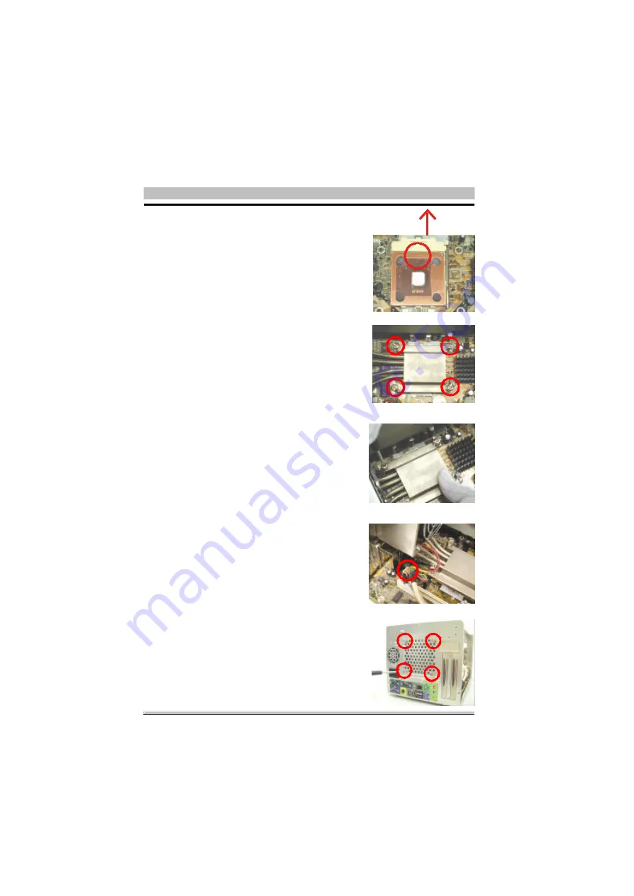
6. Insert the four screws in the holes on the heat-

pipe’s four cut edges; later place the heat-pipe
on the CPU socket and match the screws with
the holes on the socket.


先將四顆螺絲放入熱導管四個切角孔內。

把熱導管置於

CPU

腳座上,並將螺絲對齊腳座

孔洞後置入。

7. Screwing the heat-pipe on the CPU socket.

Note that press down the diagonal cut edge as
screwing or unscrewing the other.
Note: Set the weight under 4KG as using an

electric screwdriver.


將螺絲鎖入

CPU

腳座或將螺絲自

CPU

腳座鬆

開時,請按壓其對角線端,再將螺絲一一鎖入
或鬆開。
注意: 使用電動螺絲起子時,請將重力設於

4KG 以下。

8. Plug the fan’s power to the CPU fan connector

on the mainboard.

將風扇電源線插入主機板上之

CPU

風扇插座。

9. Screwing the heat-pipe to the back-panel.

用所附的4顆螺絲將熱導管固定於機殼背板
上。

5. Place the copper shim on top of CPU die.

Follow the directional word, 

UP

 as mounting.

CPU

保護銅片置於

CPU

上,安裝時請注意

銅片上之字樣


UP

必須朝向腳座上之

SOCKET

462

字樣。

UP

Summary of Contents for SK41G

Page 1: ...XPC Installation Guide XP C Use for SK41G M645...

Page 2: ...reserves the right to revise the manual or include changes in the specifications of the product described within it at any time without notice and without obligation to notify any person of such revi...

Page 3: ...e XPC FCC FCC 15 B FCC Copyright 2002 by Shuttle Inc All Rights Reserved 2002 Window s95 Window s98 Window sME Words Microsoft Corporation IBM International Business Machines Corporation AMD AMDCorpor...

Page 4: ...all 5 2 3 1 SK41G Series 7 2 3 CPU And Cooler Installation 7 2 4 Install DDR SDRAM 9 2 5 1 Install HDD Cable 10 2 5 2 Install CD ROM Cable 10 2 5 3 Install Rack 11 2 5 Install Cables And Rack 10 2 6 I...

Page 5: ...e cube shaped mini bare bone system XPC next gene ration PC due to the fact that Shuttle believes the next generation PC should be small light weight easy to use and should look distinctively differen...

Page 6: ...LED Power Switch Reset Mic SPDIF Out USB USB 1394 1394 Earphone Central Bass Surround R L Line In Front R L Power Code AC COM1 2 1 2 VGA VGA 1394 1394 LAN Port 10 100 Base T USB USB PS 2 Keyboard PS...

Page 7: ...le x 1 4 IDE x 1 5 HDD IDE cable x 1 5 IDE x 1 6 Power cord x 1 6 x 1 7 XPC installation guide x 1 7 XPC x 1 8 Mainboard CDx 1 8 x 1 9 Mainboard manual x 1 9 x 1 10 Installation kit screws etc x 1 10...

Page 8: ...e identical to its socket or slots 2 The Red line of cables ex FDD HDD and 1 marked on the socketor slots allstand for the firstpin Please make sure before fabricate 1 2 Back Panel Floppy Connector CP...

Page 9: ...5 1 Remove 3 screws of chassis cover 2 2 Start To Insatll 2 2 1 Ope n Cha ssis Cover 2 Remove the cover 2 2 2 Remo ve HDD FDD CD ROM Rac k 1 Remove 4 screws of rack 2 1 2 Remove the rack...

Page 10: ...nnector 3 Fold FDD cable under power supply 4 Fix FDD cable onto the power and chassis rail with adhesive from acces sory pack power power 2 2 3 In stall FDD C able 1 FDD cable 4 Remove all front cove...

Page 11: ...up the CPU socket lever to 90 degree angle Socket 462 CPU 90 Note SK41G supports AMD Socket 462 Athlon XP Duron processor Please follow our steps to complete the CPU installation SK41G AMD Athlon XP D...

Page 12: ...on the CPU socket Note that press down the diagonal cut edge as screwing or unscrewing the other Note Set the weight under 4KG as using an electric screwdriver CPU CPU 4KG 8 Plug the fan s power to t...

Page 13: ...1 Unlock the DIMM latch DIMM 2 Plug DDR module into the DIMM slot and lock the latch DDR 3 Check if the DDR module is well installed DIMM Install the DDR module to the DIMM1 DIMM2 2 4 Install DDR SDRA...

Page 14: ...DD cable as picture shows IDE IDE1 IDE2 2 5 2 Ins tall C D ROM Cable 1 CD ROM cable 2 5 Install Cables And Rack 2 5 1 Install HDD Cable 1 HDD cable 2 Plug the cable to the IDE 2 connector IDE2 Note Re...

Page 15: ...ront panel pin pin 3 Follow the picture to secure the cable to the chassis 4 Let the cable through the reserved hole 5 Leave the cable as picture shows 2 5 3 Insta ll Rack 1 Place CD ROM FDD HDD on th...

Page 16: ...n chassis close 2 Tighten all the devices with their own screws 3 Please tighten the screws on the standard line to make sure that FDD CD ROM will be in the same level with front panel 4 Leave the cab...

Page 17: ...13 6 Tighten the rack with 2 screws 5 Put the rack into the chassis...

Page 18: ...ctor and cable to the FDD 3 Connect HDD power connector and cable to the HDD 2 Put HDD power conncotor in the rack Clip 1 Put HDD cable in the rack clip 2 6 Install Peripherals HDD cable Power connect...

Page 19: ...e it with when fabricate the CD ROM cable 5 Plug IDE cable and power connector to CD ROM CD ROM cable Power connector 2 7 Install Accessories 2 7 1 Ins tall front feet 1 Take out 2 front feet from acc...

Page 20: ...d AGP PCI 1 Take AGP Card for example to install expansion card AGP 2 Remove 2 screws from back panel bracket and lift up AGP PCI door 2 AGP PCI 3 Install AGP Card into AGP slot and tighten it with sc...

Page 21: ...17 2 8 1 Clos e the C hassis Cover 1 Shut the cover and tighten it with screws 2 8 Complete 2 8 2 Complete 2 1...

Reviews: