


FP1
FP3
PGXD
BIAS
AUDIO
0dB
-10dB
AUDIO
0dB
-10dB
4
Adjusting Gain
FP1 and FP3
Perform a sound check. Use the
audio gain control located on the
side (FP1) or front (FP3) of the
unit to adjust the gain up (+) or
down (−) until desired level is
reached.
FP3 only:
Adjust so the audio
input level indicator flickers yellow
at peak sound levels.
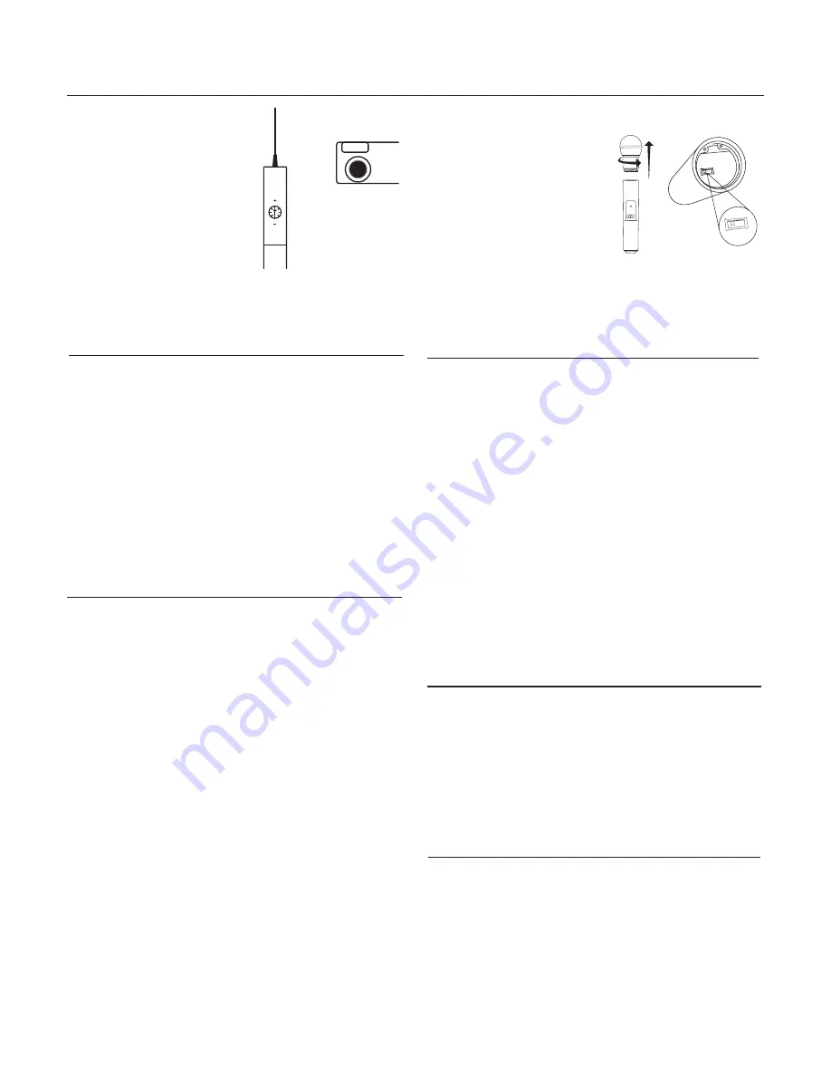
FP2
The handheld transmitter normally
does not require adjustment and
should be left at 0dB
for most ap-
plications. Only use the –10dB set-
ting for loud singing or other high
SPL applications if there is noticable
distortion.
Access the gain adjustment switch
by unscrewing the head of the micro-
phone. Use the tip of a pen or a small
screwdriver to move the switch:
0dB:
For normal use.
Single System Setup
1.
Perform a group scan:
Press and hold the
scan
button for 3 seconds. After the scan com-
pletes, the new group and channel is automatically activated and
saved.
2.
Synchronize the transmitter:
Align the transmitter and receiver infrared (IR) ports and press the
sync
button.
After a successful sync, the transmitter LED momentarily flashes and
the blue RF LED illuminates.
Multiple System Setup
Use the following steps to ensure the best performance when using mul-
tiple wireless systems at the same location.
1. Turn all receivers
on
and all transmitters
off
.
Note:
Turn on any other digital equipment that could cause interfer-
ence during the performance so it will be detected during the frequen-
cy scans in the following steps.
2. Perform a group scan using the first receiver by pressing and holding
the
scan
button for 3 seconds.
3. Turn on the first transmitter and sync it to the receiver.
For each additional system:
1. Manually set the group number to match the first receiver (see Manual
Group and Channel Selection).
2. Perform a channel scan by pressing the
scan
button.
3. Sync the transmitter to the receiver.
Important:
After syncing each transmitter, leave it on so that scans from
the other receivers do not select that channel. Be sure only one transmit-
ter IR port is exposed when synchronizing each system.
Manual Group and Channel Selection
(receiver only)
Important:
Most single-system applications do not require manual group
or channel settings--use an automatic frequency scan instead. However,
it may be useful for some applications, such as to tune to and record au-
dio directly from a microphone in a compatible wireless installation.
To set the group:
1. Press the
scan
and
sync
buttons simultaneously. The
GROUP
display
flashes.
2. Press the
sync
button to change the group number.
3. Press
scan
to accept the selected group.
4. Press
scan
again to save and exit.
5. If desired, perform a channel scan to select an open channel in that
group.
To set the channel:
1. Press the
scan
and
sync
buttons simultaneously. The
GROUP
display
flashes.
2. Press
scan
to move to the channel setting. The
CHANNEL
number
flashes.
3. Press the
sync
button to advance to the desired channel number.
4. Press
scan
to save and exit.
Note:
Remember to sync the transmitter to the receiver.
Automatic Frequency Scan
If you experience RF interference, switch to a new channel using the
channel or group scan.
Channel scan:
Press the
scan
button on the receiver. Switches to new
channel in the same group.
Group scan:
Press and hold the
scan
button for 3 seconds. Finds a new
group and selects an open channel in that group. (Do not use in multiple
system setups unless all systems are moved to the same group.)
Locking and Unlocking the Transmitter
Locking the transmitter prevents accidental changes during
performances.
To lock the controls:
With the transmitter off, hold the power button
down until the green LED flashes (~5 seconds)
To unlock the controls:
With the transmitter on, hold the power button
down until the green LED flashes (~5 seconds)
FP2
–10dB:
Use only if audio distorts due to high SPL levels.