Antenna Height
Receiver antennas should be clear of obstructions,
including human bodies, which can absorb RF. Therefore,
placing the antennas higher than “crowd level” (5 or 6 feet,
2 m, from the floor) is always recommended.
Antenna Orientation
Receiving antennas should be oriented in the same
plane as the transmitting antenna. Since th e transmitting
antenna is generally in the vertical position, receiving
antennas should also b
e vertical. However, handheld
transmitter antennas, because of the dynamics of
live performers, can sometimes vary in position. As a
compromise, antennas can be placed at approximately a 45-
degree angle from vertical. Additionally, never orient antennas
horizontally! This sometimes occurs when antennas are
mounted on the back of the receivers, inside an equipment
rack where there is not enough clearance for vertical
orientation. If this situation arises, either obtain the necessary
parts to front-mount the antennas, or remote-mount them
outside the rack (see Antenna Remoting). Antennas must
always be kept clear of any metal surfaces by at least a few
inches and not touch or cross other receiving antennas.
Antenna distribution systems can help avoid some of these
problems, and they will be discussed in the next section.
ANTENNA DISTRIBUTION
Proper antenna distribution is key to achieving
optimum performance from multiple wireless systems
operating in the same environment. Stacking or rack
mounting wireless receivers results in many closely spaced
antennas, which is not only unsightly and a physical
challenge, but actually degrades the performance of
the wireless systems. Antennas spaced less than 1/4
wavelength apart disrupt the pickup patterns of one
another, resulting in erratic coverage. Additionally, closely
spaced antennas can aggravate local oscillator bleed,
which is a potential source of interference between closely
spaced receivers. Finally, for remote antenna applications,
antenna distribution is essential to keeping the number of
remote antennas and coaxial cable runs to a minimum.
Antenna distribution eliminates these issues by splitting the
signal from a single pair of antennas to feed multiple
receivers. Splitting can be accomplished by either passive
or active means.
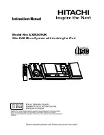
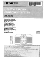
Passive Splitters
(2 receivers)
Passive splitters are inexpensive and do not require
any power to operate. Using a passive splitter results in a
signal loss of about 3 dB for every split. As a general
rule, no more than 5 dB of loss is acceptable between
the antennas and the receiver inputs. For this reason,
passive splitters should only be used for a single split (i.e.,
splitting a single antenna to two receivers). An additional
consideration with passive splitters is the presence of DC
voltage on the antenna inputs of some receivers. This
voltage is usually present for powering remote antenna
amplifiers directly off a receiver. If two receivers are
connected together with a passive splitter, each receiver
will “see” the voltage from the other receiver at its antenna
inputs. Depending on the design of the receiver, this may
be a problem. To avoid any potential damage, either use a
splitter that incorporates circuitry to block the voltage,
use an external DC blocker, or defeat the voltage on at
least one of the receivers.
7
ANTENNA SETUP
Wireless Systems Guide for
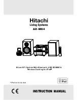
✓
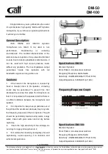
OK
proper and improper antenna and receiver placement
Summary:
• Always maintain line-of-sight from
transmitting antenna to receiving antenna.
• Separate antennas by at least one-quarter
wavelength.
• Orient receiving antennas in the same
plane as transmitting antennas
(typically a 45-degree angle).
Summary of Contents for ANTENNA SETUP
Page 2: ......