Shure Incorporated
7/9
6.
Place the bracket underneath the table, with the tube going through the hole. For thicker tables (≥ 55 mm), turn
the bracket upside down for additional clearance.
Note:
maximum table thickness = 73 mm (2.87 in).
Page 1: ...cement part information Tip This process assumes that both ends of the network cable are accessible If the other end of the network ca ble is not accessible before installing the tube and plugging in...
Page 2: ...Shure Incorporated 2 9 Installation Process 1 Remove the 3 screws located in the center on the bottom of the microphone...
Page 3: ...work cable into the microphone and guide it through the center exit path When the cable is secured guide it through the tube Note If necessary remove the retaining tabs to install thicker cable Replac...
Page 4: ...Shure Incorporated 4 9 3 Align the tube into the recessed area in the center of the microphone Install the 3 screws removed in step 1 to secure the tube...
Page 5: ...Shure Incorporated 5 9 4 Drill a 143 mm 5 5 8 in hole through the table and then place the tray into the hole...
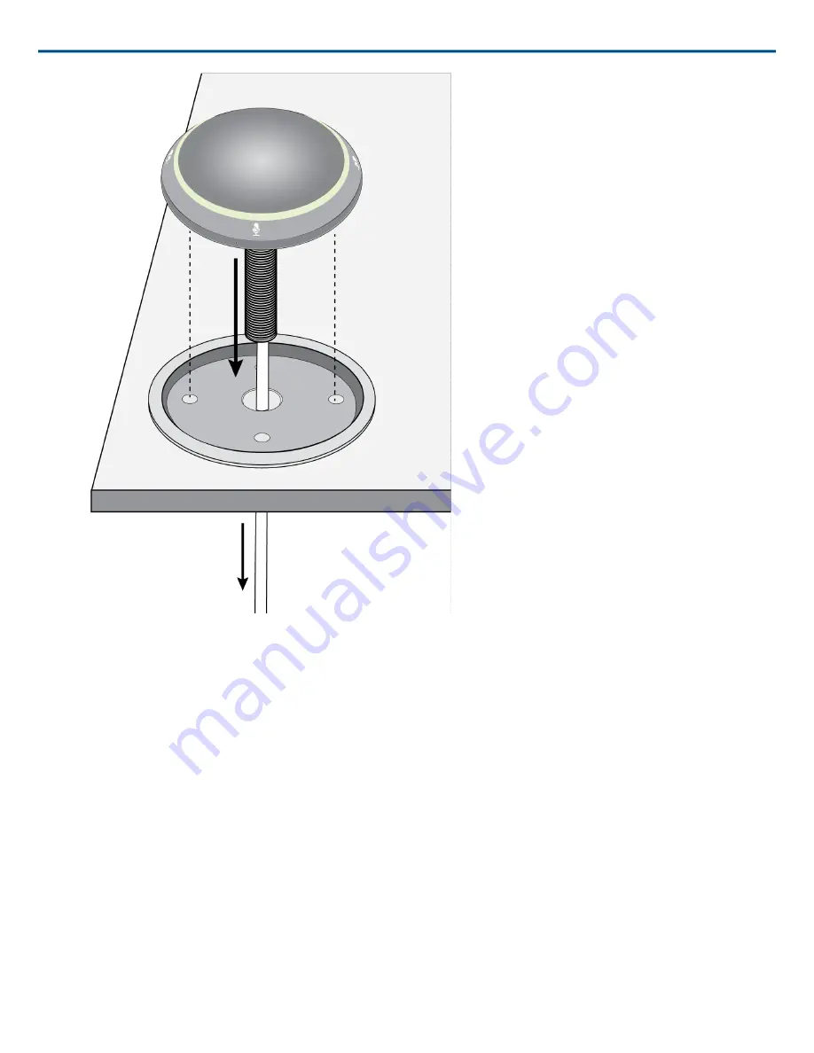
Page 6: ...the tray Then place the tube through the hole in the table and gently press the microphone into the tray Align the Shure logo on the microphone with the Shure logo on the tray The four rubber feet on...
Page 7: ...porated 7 9 6 Place the bracket underneath the table with the tube going through the hole For thicker tables 55 mm turn the bracket upside down for additional clearance Note maximum table thickness 73...
Page 8: ...able through the wing nut and attach the wing nut onto the tube from underneath the table Then tighten the wing nut to secure the bracket against the table Optional use the hole in the wing nut to ins...
Page 9: ...Shure Incorporated 9 9 Dimensions...