SHOWTEC TR-512 User Manual Download Page 26


25 


TR-512 Install 

Product code: 50826 


Mode 

In this submenu you can set recording options. 

01)


Press the ENTER button to open the menu. 

02)


Press the UP/DOWN buttons to select one of the 3 recording modes:  


MANUAL: 

Start and stop recording manually. 


SEMI_AUTO:  Recording starts when the value of a DMX channel is higher than 0. When the DMX 

channel values are set to 0, or Blackout on the light controller is active, recording 
will not start. Once recording has started, selecting STOP RECORD to stop it 
manually. 


AUTO:  

Recording starts when the value of a DMX channel is higher than 0. Stop recording 
by setting all DMX channel values to 0 or activate Blackout on the light controller. 

03)


Press the ENTER button to confirm your choice. 

04)


Press the UP/DOWN buttons to select START RECORD. 

05)


Press the ENTER button to confirm. 

06)


If the display shows WAITING START, press the ENTER button again to start recording. 

07)


Press the ENTER button to stop recording. The recorded program will be saved. 
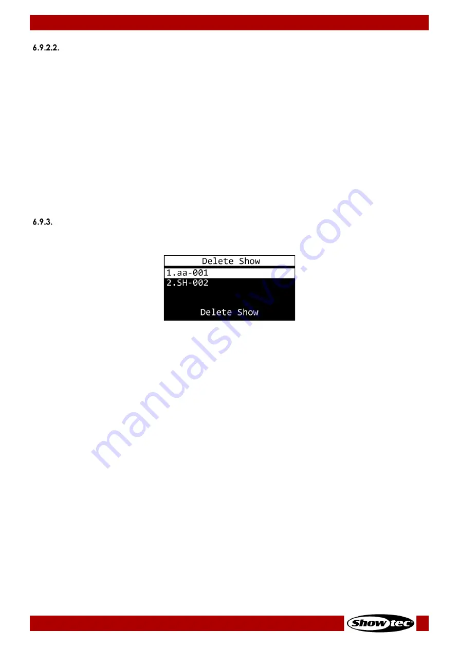
 

Delete Show 

In this menu you can remove the previously recorded programs. 


01)


Press the UP/DOWN buttons to select the program you want to delete. 

02)


Press the ENTER button to confirm your choice. DELETE SHOW will illuminate. 

03)


Press the ENTER button to delete the program. 

04)


Repeat steps 1–3 to delete other programs. 

If the program that you want to delete is assigned to any active trigger event, the device will display a 
message. 

01)


Press the UP/DOWN buttons to choose CONTINUE (to delete the program) or RETURN (to return to the 
previous menu) 

02)


Press the ENTER button to confirm your choice. 


Summary of Contents for TR-512

Page 1: ...TR 512 Install Highlite International B V Vestastraat 2 6468 EX Kerkrade the Netherlands Product code 50826 USER MANUAL ENGLISH V1...

Page 2: ...sal of the device Non observance of the instructions in this user manual may result in serious injuries and damage of property 2021 Showtec All rights reserved No part of this document may be copied p...

Page 3: ...ting 11 Connecting to Power Supply 12 5 Setup 13 Warnings and Precautions 13 DMX Connection 13 DMX 512 Protocol 13 DMX Cables 13 Setup Examples 14 Program Recording Setup 14 Program Playing Setup 15 C...

Page 4: ...ption 29 Version 29 Save Configuration 30 Load Configuration 31 Default Setting 31 7 Troubleshooting 32 8 Maintenance 33 Preventive Maintenance 33 Basic Cleaning Instructions 33 Corrective Maintenance...

Page 5: ...croSD card User manual Fig 01 Intended Use This device is designed to be used as a professional DMX trigger recorder It is suitable for indoor installation in an electrical enclosure Any other use not...

Page 6: ...tuation which if not avoided may result in minor or moderate injury Attention Indicates important information for the correct operation and use of the product Important Read and observe the instructio...

Page 7: ...e is sufficient for the required power consumption of the device Attention General safety Do not block the ventilation openings Without proper heat dissipation and air circulation the internal compone...

Page 8: ...ite International dealer for more information Instructed persons have been instructed and trained by a skilled person or are supervised by a skilled person for specific tasks and work activities assoc...

Page 9: ...e to set a delay which enhances your control of the programs The TR 512 Install is suitable for a large range of venues such as theme parks museums shops and many others Front View Fig 02 01 12 V DC 2...

Page 10: ...tor IN maximum cable gauge 1 5 mm2 AWG 12 12 V Phoenix connector OUT maximum cable gauge 1 5 mm2 AWG 12 Input connections 6 x 2 pin Phoenix terminal trigger GPIO connector IN maximum cable gauge 1 5 m...

Page 11: ...10 TR 512 Install Product code 50826 Dimensions Fig 03...

Page 12: ...on Site Requirements The device must be installed only indoors The device can be mounted on a 35 mm DIN rail The maximum ambient temperature ta 40 C must never be exceeded The relative humidity must n...

Page 13: ...n the information label on the device Make sure that the cross sectional area of the power cable is sufficient for the required power consumption of the device 01 Remove the 2 pin Phoenix terminal pow...

Page 14: ...IN and OUT Phoenix terminal connectors The pin assignment is as follows 3 pin pin 1 ground pin 2 pin 3 Note Maximum recommended DMX data link distance 300 m DMX Cables Shielded twisted pair cables mus...

Page 15: ...connector OUT 06 Fig 08 02 Connect a DMX 512 light controller to the device s 3 pin Phoenix terminal DMX connector IN 05 and connect light fixtures to the device s 3 pin Phoenix terminal DMX connector...

Page 16: ...es 02 Disconnect the DMX 512 light controller from the device 03 Connect the external trigger devices See 5 3 2 1 Connecting External Trigger Devices on page 16 or 5 3 2 2 Connecting the TR 512 Instal...

Page 17: ...er devices movement sensors temperature sensors light sensors etc to the device s 2 pin 1 6 GPIO Phoenix terminal connectors IN 09 Fig 13 03 Optionally you can connect a 12 V device e g a LED indicato...

Page 18: ...ig 15 01 Connect the wall panel to the device with an RJ 45 cable Recommended maximum cable length 25 m 02 Install the wall panel in two ways with or without the jumper See Fig 16 With the jumper Set...

Page 19: ...18 TR 512 Install Product code 50826 03 Make sure that the RJ 45 cable has the following pinout Fig 17...

Page 20: ...o the power supply make sure that the current voltage and frequency match the input voltage current and frequency specified on the information label on the device Start up 01 Before you power the devi...

Page 21: ...into the device 03 Record a program See 6 9 2 Record Show on page 24 for more information During recording the LED indicator 11 will be blinking See 6 7 LED Statuses on page 21 for more information 04...

Page 22: ...name SHOW Assigned DMX program s name TIME Playing time STATUS PLAYING trigger is active or WAITING trigger is inactive DELAY Delay time LED Statuses There are 4 LED indicators 10 11 12 13 on the con...

Page 23: ...22 TR 512 Install Product code 50826 Menu Overview...

Page 24: ...am You can only play one program at a time Note You need to program at least one program in order to be able to play it For more information please read 6 9 2 Record Show page 24 01 Press the UP DOWN...

Page 25: ...he UP DOWN buttons to select one of the 2 submenus NAME See 6 9 2 1 Name on page 24 for more information MODE See 6 9 2 2 Mode on page 25 for more information 02 Press the ENTER button to open the sel...

Page 26: ...e ENTER button to confirm your choice 04 Press the UP DOWN buttons to select START RECORD 05 Press the ENTER button to confirm 06 If the display shows WAITING START press the ENTER button again to sta...

Page 27: ...ation DELAY See 6 9 4 5 Delay on page 27 for more information 04 Press the ENTER button to open the desired submenu Once you have adjusted all the options in menus 6 9 4 1 6 9 4 5 save your trigger ev...

Page 28: ...laying until it ends and then it will stop With only a short pulse the program will play just once NC_TR Normally Closed Trigger will be activated when the circuit opens As long as the circuit remains...

Page 29: ...2 DMX Port Option on page 29 for more information DISPLAY OPTION See 6 9 6 3 Display Option on page 29 for more information VERSION See 6 9 6 4 Version on page 29 for more information 02 Press the EN...

Page 30: ...is submenu you can set the display options 01 Press the UP DOWN buttons to select one of the 3 modes MODE Choose between NORMAL normal view and INVERSE display flip If you choose INVERSE the button fu...

Page 31: ...ss the ENTER button 04 Press or press and hold down for quick search the UP DOWN buttons to select the desired character 05 Press the ENTER button to confirm your choice 06 Repeat steps 1 5 to edit th...

Page 32: ...ns and you want to return to the previous menu Default Setting In this menu you can restore default factory settings 01 Press the UP DOWN button to choose between the 2 options YES The default factory...

Page 33: ...robable cause s Solution The device does not function at all No power to the device Check if power is switched on and cables are plugged in Check if the external power supply is connected properly and...

Page 34: ...tion points The power cables are not damaged and do not show any material fatigue Basic Cleaning Instructions To clean the device follow the steps below 01 Disconnect the electrical enclosure from the...

Page 35: ...osal of this product Waste Electrical and Electronic Equipment This symbol on the product its packaging or documents indicates that the product shall not be treated as household waste Dispose of this...

Page 36: ...2021 Showtec...

Reviews: