background image


Control Modes  


FUNCTIONS: 

There are 4 modes:    

• Static Colors 
• Built-in programs Auto run 
• Master/Slave  
• DMX512 (3, 3, 4, 10 or 24 Channels) 


One Spectral 

(

Static Colors

)


1)


Fasten the effect light onto firm trussing. Leave at least 0,5 meter on all sides for air circulation. 

2)


When the Spectral is not connected by a DMX-cable, it functions as a stand-alone device.


Please 

see page 13 for more information about the static colors. 


One 

Spectral

 (

Built-in Programs

)


1.


Fasten the effect light onto firm trussing. Leave at least 0,5 meter on all sides for air circulation. 

2.


When the Spectral is not connected by a DMX-cable, it functions as a stand-alone device.


Please 

see page 14 for more information about the built-in programs. 


Multiple Spectrals (Master/Slave control)


1.


Fasten the effect light onto firm trussing. Leave at least 0,5 meter on all sides for air circulation. 

2.


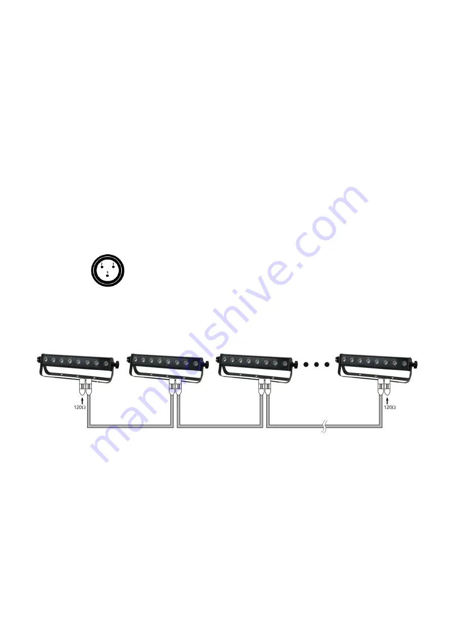
Use a 3-p XLR cable to connect the Spectral.


The pins: 


1. 

Earth 

2. 

Signal  - 

3. 

Signal  + 


3.


Link the units as shown in (Fig. 3), Connect a DMX signal cable from the first unit's DMX "out" socket to 
the second unit's "in" socket. Repeat this process to link the second, third, and fourth units. 

You can 

use the same functions on the master device as described on page 13+14 (Static Colors or Built-in 
Programs

). This means on the master device you can set your desired operation Mode and all slave 

devices will react the same as the master device.  


Multiple Spectrals (Master/Slave control) 


Fig. 3 


Multiple Spectrals (DMX Control)


1.


Plug the end of the electric mains power cord into a proper electric power supply socket

2.


Use a 3-p XLR cable to connect the Spectrals

3.


Link the units as shown in (figure 4), Connect a DMX signal cable from the first unit's DMX "out" socket 
to the second unit's "in" socket. Repeat this process to link the second, third, and fourth units

4.


Supply electric power: Plug the end of the mains power cord into proper electric power supply 
sockets. Do so for all units and the controller. 


Summary of Contents for Spectral CYC650

Page 1: ...Spectral CYC650 V2 ORDERCODE 43519 Highlite International B V Vestastraat 2 6468 EX Kerkrade The Netherlands Phone 31 45 5667700 ...

Page 2: ... on Showtec for more excellent lighting products We design and manufacture professional light equipment for the entertainment industry New products are being launched regularly We work hard to keep you our customer satisfied For more information iwant showtec info You can get some of the best quality best priced products on the market from Showtec So next time turn to Showtec for more great lighti...

Page 3: ...l 11 DMX Control Mode 11 DMX Addressing 11 Menu Overview 12 Main Menu Options 13 1 Creating a static color 13 2 Activating an Auto Program 14 3 DMX 512 Address 14 4 Run Mode 15 5 Personality 15 6 Changing the Settings 16 7 FACTORY DEFAULT SETTINGS 16 8 Edit Custom 17 9 Fans 17 10 White Settings 18 11 White Settings RGB Recalibration 18 12 Activate Password 18 How to make your own Custom Program 19...

Page 4: ...ons If improving on this lifespan expectancy is of a higher priority place care in providing for lower operational temperatures This may include climatic environmental and the reduction of overall projection intensity Safety Instructions Every person involved with the installation operation and maintenance of this device has to be qualified follow the instructions of this manual Before your initia...

Page 5: ...me Make sure that no side forces can impact on the truss system The cable insert or the female part in the device must never be strained There must always be sufficient cable to the device Otherwise the cable may be damaged which may lead to deadly electrical shocks If the external cable is damaged it has to be replaced by a qualified technician If the lens is obviously damaged it has to be replac...

Page 6: ...sues Do not attempt the installation yourself Always let the installation be carried out by an authorized dealer Procedure If the Spectral CYC650 is lowered from the ceiling or high joists professional trussing systems have to be used Use a clamp to mount the Spectral CYC650 with the mounting bracket to the trussing system The Spectral CYC650 must never be fixed swinging freely in the room The ins...

Page 7: ...hod to use Note If you are given an RMA number please include the following information on a piece of paper inside the box 1 Your name 2 Your address 3 Your phone number 4 A brief description of the symptoms Claims The client has the obligation to check the delivered goods immediately upon delivery for any short comings and or visible defects or perform this check after our announcement that the g...

Page 8: ...put Drive current 350mA Peak Power 154 Watt Continuous Power 82 Watt On board Display for Auto and Custom control Control protocol DMX 512 Control personality TOUR PIXEL ARC1 ARC1 D HSV Dimmer 0 100 Strobe 0 20Hz Cooling Forced Cooling Fan Overheat Protection 3 3 4 10 or 24 channel LED wash light 4 different DMX Operating modes Colour temperature presets 3 200 K 10 000 K Built in automated program...

Page 9: ... Pixel 2 Green 6 Pixel 2 Blue 7 Pixel 3 Red 8 Pixel 3 Green 9 Pixel 3 Blue 10 Pixel 4 Red 11 Pixel 4 Green 12 Pixel 4 Blue 13 Pixel 5 Red 14 Pixel 5 Green 15 Pixel 5 Blue 16 Pixel 6 Red 17 Pixel 6 Green 18 Pixel 6 Blue 19 Pixel 7 Red 20 Pixel 7 Green 21 Pixel 7 Blue 22 Pixel 8 Red 23 Pixel 8 Green 24 Pixel 8 Blue ARC1 Channel Description 1 Red 2 Green 3 Blue ARC1 D Channel Description 1 Master Dim...

Page 10: ...king materials from the Spectral CYC650 Check that all foam and plastic padding is removed Connect all cables Do not supply power before the whole system is set up and connected properly Always disconnect from electric mains power supply before cleaning or servicing Damages caused by non observance are not subject to warranty Set Up and Operation Before plugging the unit in always make sure that t...

Page 11: ...LR cable to connect the Spectral The pins 1 Earth 2 Signal 3 Signal 3 Link the units as shown in Fig 3 Connect a DMX signal cable from the first unit s DMX out socket to the second unit s in socket Repeat this process to link the second third and fourth units You can use the same functions on the master device as described on page 13 14 Static Colors or Built in Programs This means on the master d...

Page 12: ...d be connected on one data link Connecting more than 30 fixtures on one serial data link without the use of a DMX optically isolated splitter may result in deterioration of the digital DMX signal Maximum recommended DMX data link distance 100 meters Maximum recommended number of Spectrals on a DMX data link 30 fixtures 220V 24 units may be connected in series 120V 12 units may be connected in seri...

Page 13: ...esses right Therefore the DMX address of the first Spectral should be 1 001 the DMX address of the second Spectral should be 1 24 25 the DMX address of the third Spectral should be 25 24 49 etc Please be sure that you don t have any overlapping channels in order to control each Spectral correctly If two or more Spectrals are addressed similarly they will work similarly For address settings please ...

Page 14: ...12 Menu Overview Do not use this option ...

Page 15: ...ough this menu 2 Use the UP DOWN buttons to change the static colors Red Green Blue or the strobe speed 0 20Hz 3 Press MENU to go 1 step back 4 You can combine RED GREEN and BLUE to create an infinite range of colors 0 255 Red Strobe Set the value of the red LEDs 0 255 Set the value of the flash 0 20Hz Green Set the value of the green LEDs 0 255 Blue Set the value of the blue LEDs 0 255 ...

Page 16: ...rams 2 Press ENTER after selecting the desired auto program You can select the auto speed of the 10 built in programs from 000 255 3 You can also edit 10 custom programs 3 DMX 512 Address 1 When you press ENTER in menu DMX 512 address you can set the DMX address 2 You can choose your DMX address between 001 512 ...

Page 17: ...ntrol the Spectral SLAVE mode is for using the device during a Master Slave operation When the fixtures are in Auto program operation the RUN MODE does not work 5 Personality Enter the PERSONALITY mode to select a DMX mode TOUR PIXEL ARC1 ARC1 D HSV TOUR 10 channels PIXEL 24 channels ARC1 3 channels ARC1 D 4 channels HSV 3 channels ...

Page 18: ... 3 4 are speed modes of the non linear dimmer DIM1 is fastest and DIM4 is slowest The DIM setting does not have any effect in TOUR mode The DMX setting overrules the DIM setting 4 The Color settings menu enables you to activate deactivate the color calibration functions When you have selected RGBW to ON RGB TO WHITE has been set This means RGB 255 255 255 The color is displayed as you have calibra...

Page 19: ...n be edited 3 Each step allows the creation of a scene using RED GREEN BLUE STROBE STEP TIME FADE 9 Fans With this menu you are able to control the fan speed of the device 1 Press Menu until the display shows FANS 2 Press enter to open this menu Scroll through the menu to set the desired fan speed IMPORTANT Do no use the FAN OFF option The device can become damaged and warranty will become void ...

Page 20: ...B Recalibration 1 RGB TO WHITE can be edited by using RED GREEN and BLUE 12 Activate Password 1 Enter the KEY LOCK mode to select whether the access password is On or Off 2 The Access Password UP DOWN UP DOWN 3 When you have pressed ENTER in menu KEY ON it will take 30 seconds before the Spectral is locked 4 When the password is activated the display will ask for password each time the fixture is ...

Page 21: ...Up Down to change the values Use Up Down to change the values Use Up Down to change the values Use Up Down to change the values Use Up Down to change the values 1 And so you can add a maximum of 30 scenes 2 After that you can start with CUSTOM02 and create a maximum of 30 scenes again 3 You can repeat these steps until you ve reached CUSTOM10 step 30 4 This means it is possible to create 300 separ...

Page 22: ...wn Green Down Blue 100 Red 100 Green 100 Blue 100 White 1 3200K White 2 3400K White 3 4200K White 4 4900K White 5 5600K White 6 5900K White 7 6500K White 8 7200K White 9 8000K White 10 8500K White 11 10000K 6 000 009 Strobe No Function 010 255 0 20 Hz 7 000 010 011 020 021 030 031 040 041 060 061 070 071 080 081 090 091 100 101 110 111 120 121 130 131 140 141 150 151 160 161 170 171 180 181 190 19...

Page 23: ...ntensity of each respective color Channels 2 3 and 4 can be combined to create an unlimited range of colors COLOR MACROS WHITE BALANCE Channel 5 selects the required COLOR MACRO and whites in different colors Channel 5 has priority over channels 2 3 and 4 Channel 1 is used to control the intensity of the COLOR MACRO STROBE CH6 is the strobe channel and controls the strobe effects of CH2 CH3 CH4 an...

Page 24: ... 000 255 Block 3 Blue 0 100 10 000 255 Block 4 Red 0 100 11 000 255 Block 4 Green 0 100 12 000 255 Block 4 Blue 0 100 13 000 255 Block 5 Red 0 100 14 000 255 Block 5 Green 0 100 15 000 255 Block 5 Blue 0 100 16 000 255 Block 6 Red 0 100 17 000 255 Block 6 Green 0 100 18 000 255 Block 6 Blue 0 100 19 000 255 Block 7 Red 0 100 20 000 255 Block 7 Green 0 100 21 000 255 Block 7 Blue 0 100 22 000 255 B...

Page 25: ...255 Blue 0 100 4 Channel ARC1 D Channel Value Function 1 000 255 Master Dimmer 0 100 2 000 255 Red 0 100 3 000 255 Green 0 100 4 000 255 Blue 0 100 3 Channel HSV Channel Value Function 1 000 255 Hue Color variations 0 100 2 000 255 Saturation of color Red 0 100 3 000 255 Value Dimmer 0 100 ...

Page 26: ...24 Beam Angles ...

Page 27: ...has to make sure that safety relating and machine technical installations are to be inspected by an expert after every year in the course of an acceptance test The operator has to make sure that safety relating and machine technical installations are to be inspected by a skilled person once a year The following points have to be considered during the inspection 1 All screws used for installing the...

Page 28: ...cing the fuse 4 If all of the above appears to be O K plug the unit in again 5 If you are unable to determine the cause of the problem do not open the Spectral as this may damage the unit and the warranty will become void 6 Return the device to your Showtec dealer No Response to DMX Response Suspect the DMX cable or connectors a controller malfunction a light effect DMX card malfunction 1 Check th...

Page 29: ...pect connections and cables Correct poor connections Repair or replace damaged cables Data link not terminated with 120 Ohm termination plug Insert termination plug in output jack of the last fixture on the link Incorrect addressing of the fixtures Check address setting One of the fixtures is defective and disturbs data transmission on the link Bypass one fixture at a time until normal operation i...

Page 30: ...y TOUR PIXEL ARC1 ARC1 D HSV Peak Power 154 Watt Continuous Power 82 Watt On board Display for Auto and Custom control Control protocol DMX 512 Dimmer 0 100 Strobe 0 20Hz Cooling Forced Cooling Fan Overheat Protection 3 3 4 10 or 24 channel LED wash light 4 different DMX Operating modes Built in automated programs via DMX Recall custom programs via DMX LED display with lock out feature Beam angle ...

Page 31: ......

Reviews: