SHOWTEC 42233 Manual Download Page 20


19 


Ordercode: 42233 

Controller for Octostrip MKII 

08)


Press the SETUP button to enter and to toggle between the 2 options below. Once you have chosen 
the desired option, do as follows: 


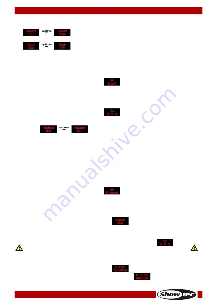
Program speed (Press the UP/DOWN buttons to increase/decrease program 
speed. The adjustment range is between 1-100, from slow to fast.) 


Strobe (Press the UP/DOWN buttons to set strobe frequency. The adjustment 
range is between 0-99, from OFF to high frequency.) 

 
09)


Once you have adjusted the settings, press the SETUP button to confirm. 


3. Master/Slave 
With this menu you can set the device as a master or a slave device. 

01)


Press the MODE button until the display shows 

 . 

02)


The device is now operating in slave mode and will react the same as the master device. 


4. DMX-512 
With this menu you can set the device’s DMX starting address and the desired DMX channel mode. 

01)


Press the MODE button until the display shows 

 . 

02)


Press the SETUP button to open the menu. 

03)


Press the UP/DOWN buttons to set the desired DMX starting address. The adjustment range is 

between 

 . 

04)


Press the SETUP button again to proceed to channel mode settings. 

05)


Press the UP/DOWN buttons to choose one of the following DMX channel modes: 


6CH, 8CH, 14CH, 24CH, 26CH, 50CH, 96CH or 112CH (for 50 cm LED strips) 


6CH, 8CH, 14CH, 24CH, 26CH, 50CH, 192CH or 208CH (for 100 cm LED strips) 

 
06)


The displayed DMX channel modes depend on the LED strip length. See 8.1., page 21. 

07)


Press the SETUP button to confirm. 


5. Network Settings 
With this menu, you can adjust the device’s properties, such as the signal source, IP address, net mask, 
net, subnet mask, universe and the MAC address. 

01)


Press the MODE button until the display shows 

 . 

02)


Press the SETUP button to open the menu. 

03)


Press the UP/DOWN buttons to toggle through the 7 options below. 

 
5.1. Signal Source 
With this menu you can select the desired signal source: DMX or ArtNet. 

01)


Press the UP/DOWN buttons until the display shows 

 . 

02)


Press the SETUP button to open the menu. 

03)


Press the UP/DOWN buttons to choose between DMX or ArtNet. 

04)


Press the SETUP button to confirm. 


If you have chosen ArtNet, press the MODE button until the display shows 

, for 

the signal to be received properly. Otherwise, the device will not function in ArtNet mode. 


5.2. IP Address 
With this menu you can set the IP address. 

01)


Press the UP/DOWN buttons until the display shows 

 . 

02)


Press the SETUP button to open the menu. The display will show 

 . 

Summary of Contents for 42233

Page 1: ...Controller for Octostrip MKII V1 Highlite International B V Vestastraat 2 6468 EX Kerkrade the Netherlands Ordercode 42233 MANUAL ENGLISH...

Page 2: ...Octostrips ArtNet Control 12 Connecting to a Network 13 ArtNet settings 13 How To Make a Data Cable 14 Software for controlling 14 Fixture Linking 15 Data Cabling 15 Control Panel 16 Control Mode 16 D...

Page 3: ...he 50 cm LED strips 43 112 channels only when using the 50 cm LED strips 44 192 channels only when using the 100 cm LED strips 46 208 channels only when using the 100 cm LED strips 47 Maintenance 49 R...

Page 4: ...t includes Showtec Controller for Octostrip MKII Pro power cable 1 5 m User manual LED Expected Lifespan LEDs gradually decline in brightness over time HEAT is the dominant factor that leads to the ac...

Page 5: ...ctions Avoid flames and do not put close to flammable liquids or gases Always hold the fixture by the transport handles Always keep the case closed while operating Always allow a free air space of at...

Page 6: ...evice is operated in any other way than the one described in this manual the product may suffer damages and the warranty becomes void Any other operation may lead to dangers like short circuit burns e...

Page 7: ...n proper UPS packing or double boxing is always a safe method to use Note If you are given an RMA number please include the following information on a piece of paper inside the box 01 Your name 02 You...

Page 8: ...trip MKII However in such case it is not advisable to operate the old and the new version of the device in Auto mode as the built in programs differ per version Power supply 100 240V AC 50 60Hz Power...

Page 9: ...ON OFF 03 Fuse T2L 250V 04 Ground earth connection 05 Pro power connector Blue 100 240V IN 06 Pro power connector Grey 100 240V OUT 07 3 pin DMX signal connector IN 08 RJ45 ArtNet signal connector IN...

Page 10: ...ole system is set up and connected properly Always disconnect from electric mains power supply before cleaning or servicing Damages caused by non observance are not subject to warranty Set Up and Oper...

Page 11: ...20 and 21 for more information about Auto Built in programs Sound controlled and Static Colors modes Multiple Octostrips Master Slave control 01 Fasten the effect light onto firm trussing Leave at lea...

Page 12: ...g a DMX signal cable Repeat this process to link the second third and fourth units 05 Connect a light controller to the first device s in socket using a DMX cable 06 Connect the included 8 LED strips...

Page 13: ...s in socket using a CAT 5 CAT 6 signal cable Repeat this process to link the second third and fourth units 05 Using a CAT 5 CAT 6 cable connect the first Octostrip s RJ45 in socket to the PC Windows...

Page 14: ...e of the first Octostrip to 1 04 Set the first Octostrip s DMX address to 001 05 If you for example want to operate the Octostrip in 8CH mode set the DMX starting address of the second Octostrip to 9...

Page 15: ...5 5E 6 and connect it to the RJ45 connector as shown in the picture below fig 07 The wires should now be colored as follows Fig 07 Software for controlling In combination with Arkaos or DMT Software...

Page 16: ...ty signal and are less prone to electromagnetic interference DAP Audio DMX Data Cables DAP Audio Basic microphone cable for allround use bal XLR M 3 pin XLR F 3 pin Ordercode FL01150 1 5 m FL013 3 m F...

Page 17: ...8 417 417 etc Please be sure that you do not have any overlapping channels in order to control each Octostrip correctly If two Octostrips are addressed similarly they will work similarly Note It is al...

Page 18: ...17 Ordercode 42233 Controller for Octostrip MKII Menu Overview...

Page 19: ...s 02 Press the SETUP button to open the menu 03 Press the UP DOWN buttons to choose the desired built in program The adjustment range is between 04 Press the UP DOWN buttons until the display shows 05...

Page 20: ...e settings 05 Press the UP DOWN buttons to choose one of the following DMX channel modes 6CH 8CH 14CH 24CH 26CH 50CH 96CH or 112CH for 50 cm LED strips 6CH 8CH 14CH 24CH 26CH 50CH 192CH or 208CH for 1...

Page 21: ...en 04 Press the SETUP button to confirm 5 5 Subnet With this menu you can set the subnet 01 Press the UP DOWN buttons until the display shows 02 Press the SETUP button to open the menu 03 Press the UP...

Page 22: ...the desired LED strip length 50 cm or 100 cm 01 When the display shows press the SETUP button to open the menu 02 Press the UP DOWN buttons to choose between 1 0M and 0 5M 03 Press the SETUP button to...

Page 23: ...annel 1 Color Macros 0 5 Not functional 6 11 Color 1 12 17 Color 2 18 23 Color 3 24 29 Color 4 30 35 Color 5 36 41 Color 6 42 47 Color 7 48 53 Color 8 54 59 Color 9 60 65 Color 10 66 71 Color 11 72 77...

Page 24: ...2 Strobe 0 4 Not functional 5 255 Strobe frequency from low to high frequency Channel 3 Built in programs Dimmer must be open 0 10 Not functional 11 22 Program 1 23 34 Program 2 35 46 Program 3 47 58...

Page 25: ...6 131 Color 21 132 137 Color 22 138 143 Color 23 144 149 Color 24 150 155 Color 25 156 161 Color 26 162 167 Color 27 168 173 Color 28 174 179 Color 29 180 185 Color 30 186 191 Color 31 192 197 Color 3...

Page 26: ...m speed CH1 must be set between 11 250 0 255 Speed adjustment from slow to fast Channel 2 Sound sensitivity CH1 must be set between 251 255 0 255 Sound sensitivity adjustment from low to high sensitiv...

Page 27: ...adjustment Red from 0 100 Channel 7 Green LED strips 1 4 CH3 must be open CH5 must be closed 0 255 Gradual adjustment Green from 0 100 Channel 8 Blue LED strips 1 4 CH3 must be open CH5 must be closed...

Page 28: ...9 180 185 Color 30 186 191 Color 31 192 197 Color 32 198 203 Color 33 204 209 Color 34 210 215 Color 35 216 221 Color 36 222 227 Color 37 228 233 Color 38 234 255 Color 39 Channel 12 Red LED strips 5...

Page 29: ...Green LED strip 2 0 255 Gradual adjustment Green from 0 100 Channel 6 Blue LED strip 2 0 255 Gradual adjustment Blue from 0 100 Channel 7 Red LED strip 3 0 255 Gradual adjustment Red from 0 100 Chann...

Page 30: ...m speed CH1 must be set between 11 250 0 255 Speed adjustment from slow to fast Channel 2 Sound sensitivity CH1 must be set between 251 255 0 255 Sound sensitivity adjustment from low to high sensitiv...

Page 31: ...stment Red from 0 100 Channel 7 Green LED strips 1 2 CH3 must be open CH1 and CH5 must be closed 0 255 Gradual adjustment Green from 0 100 Channel 8 Blue LED strips 1 2 CH3 must be open CH1 and CH5 mu...

Page 32: ...be closed 0 255 Gradual adjustment Red from 0 100 Channel 13 Green LED strips 3 4 CH9 must be open CH1 and CH11 must be closed 0 255 Gradual adjustment Green from 0 100 Channel 14 Blue LED strips 3 4...

Page 33: ...ust be open CH1 and CH17 must be closed 0 255 Gradual adjustment Red from 0 100 Channel 19 Green LED strips 5 6 CH15 must be open CH1 and CH17 must be closed 0 255 Gradual adjustment Green from 0 100...

Page 34: ...8 174 179 Color 29 180 185 Color 30 186 191 Color 31 192 197 Color 32 198 203 Color 33 204 209 Color 34 210 215 Color 35 216 221 Color 36 222 227 Color 37 228 233 Color 38 234 255 Color 39 Channel 24...

Page 35: ...rogram speed CH1 must be set between 11 250 0 255 Speed adjustment from slow to fast Channel 2 Sound sensitivity CH1 must be set between 251 255 0 255 Sound sensitivity adjustment from low to high sen...

Page 36: ...l adjustment Red from 0 100 Channel 7 Green LED strip 1 CH3 must be open CH1 and CH5 must be closed 0 255 Gradual adjustment Green from 0 100 Channel 8 Blue LED strip 1 CH3 must be open CH1 and CH5 mu...

Page 37: ...must be closed 0 255 Gradual adjustment Red from 0 100 Channel 13 Green LED strip 2 CH9 must be open CH1 and CH11 must be closed 0 255 Gradual adjustment Green from 0 100 Channel 14 Blue LED strip 2...

Page 38: ...CH15 must be open CH1 and CH17 must be closed 0 255 Gradual adjustment Red from 0 100 Channel 19 Green LED strip 3 CH15 must be open CH1 and CH17 must be closed 0 255 Gradual adjustment Green from 0 1...

Page 39: ...9 Channel 24 Red LED strip 4 CH21 must be open CH1 and CH23 must be closed 0 255 Gradual adjustment Red from 0 100 Channel 25 Green LED strip 4 CH21 must be open CH1 and CH23 must be closed 0 255 Grad...

Page 40: ...233 Color 38 234 255 Color 39 Channel 30 Red LED strip 5 CH27 must be open CH1 and CH29 must be closed 0 255 Gradual adjustment Red from 0 100 Channel 31 Green LED strip 5 CH27 must be open CH1 and C...

Page 41: ...olor 36 222 227 Color 37 228 233 Color 38 234 255 Color 39 Channel 36 Red LED strip 6 CH33 must be open CH1 and CH35 must be closed 0 255 Gradual adjustment Red from 0 100 Channel 37 Green LED strip 6...

Page 42: ...91 Color 31 192 197 Color 32 198 203 Color 33 204 209 Color 34 210 215 Color 35 216 221 Color 36 222 227 Color 37 228 233 Color 38 234 255 Color 39 Channel 42 Red LED strip 7 CH39 must be open CH1 and...

Page 43: ...r 21 132 137 Color 22 138 143 Color 23 144 149 Color 24 150 155 Color 25 156 161 Color 26 162 167 Color 27 168 173 Color 28 174 179 Color 29 180 185 Color 30 186 191 Color 31 192 197 Color 32 198 203...

Page 44: ...nt Blue from 0 100 Channel 4 Red LED strip 1 section 2 0 255 Gradual adjustment Red from 0 100 Channel 5 Green LED strip 1 section 2 0 255 Gradual adjustment Green from 0 100 Channel 6 Blue LED strip...

Page 45: ...D strip 2 0 4 Not functional 5 255 Strobe frequency from low to high frequency Channel 5 Dimmer LED strip 3 0 255 Dimmer intensity from dark to brightest Channel 6 Strobe LED strip 3 0 4 Not functiona...

Page 46: ...ction 2 CH1 must be open 0 255 Gradual adjustment Red from 0 100 Channel 21 Green LED strip 1 section 2 CH1 must be open 0 255 Gradual adjustment Green from 0 100 Channel 22 Blue LED strip 1 section 2...

Page 47: ...ent Blue from 0 100 Channel 4 Red LED strip 1 section 2 0 255 Gradual adjustment Red from 0 100 Channel 5 Green LED strip 1 section 2 0 255 Gradual adjustment Green from 0 100 Channel 6 Blue LED strip...

Page 48: ...LED strip 2 0 4 Not functional 5 255 Strobe frequency from low to high frequency Channel 5 Dimmer LED strip 3 0 255 Dimmer intensity from dark to brightest Channel 6 Strobe LED strip 3 0 4 Not functio...

Page 49: ...ction 2 CH1 must be open 0 255 Gradual adjustment Red from 0 100 Channel 21 Green LED strip 1 section 2 CH1 must be open 0 255 Gradual adjustment Green from 0 100 Channel 22 Blue LED strip 1 section 2...

Page 50: ...lacing the Fuse Power surges short circuit or inappropriate electrical power supply may cause a fuse to burn out If the fuse burns out the product will not function whatsoever If this happens follow t...

Page 51: ...e respond erratically or not at all to the controller Poor data quality Check data quality If much lower than 100 percent the problem may be a bad data link connection poor quality or broken cables mi...

Page 52: ...trip output 5 pin XLR OUT Electro mechanical effects Dimmer 0 100 Strobe 0 20Hz Housing Die cast aluminum Control protocol DMX 512 ArtNet DMX control via standard DMX controller Onboard LED display fo...

Page 53: ...52 Ordercode 42233 Controller for Octostrip MKII Dimensions...

Page 54: ...53 Ordercode 42233 Controller for Octostrip MKII Notes...

Page 55: ...54 Ordercode 42233 Controller for Octostrip MKII...

Page 56: ...2018 Showtec...

Reviews: