The computer and DRO that come with the machine are 220 volt only and
their cords are hard wired into the control box of the machine.
CAUTION: DO NOT PLUG THE COMPUTER OR DRO INTO A 110
VOLT OUTLET.
The cord comes out the back of the machine on the left side about 36” from
the floor. Measure out your location and have your outlet wired so the cord
can reach. (Use of a 3-4’ extension cord of sufficient wire gauge is
acceptable if necessary) The outlet should be about 48” from the floor. You
will also need a 110 volt outlet near the machine for any lights, fans etc. you
may want to use.
MOVING INTO PLACE AND LEVELING
Now that you are all wired and ready to move the machine into place,
screw the adjustable legs up into the bench legs until the machine is resting
on the casters. Now one person can easily roll the machine around.
However, be careful and move slowly because the machine is very top heavy,
and even a small nut or bolt could stop the caster and cause the machine to
tip over if rolling too fast. Sweep up your entire area before beginning the
move. If you are mounting the machine close to the back wall, be sure to
release the computer mount and swing it out toward the front of the
machine before getting up close to the wall. Once you are in the chosen
place, begin screwing the adjustable levelers out of the bench legs until the
machine is lifted off the casters. Most shops have concrete floors, but in the
unlikely event you are on a wood floor, you should cut some 6” X 6” steel
pads to place beneath the levelers to spread the load. Mark the place on the
floor with paint or sharpie so you can always return there if you should need
to move the machine. If you have a machinist’s level, that is great, but a
good quality carpenter’s level will work as well. Place the level on the top
carriage of the machine and begin to adjust the levelers until you are level
left to right, forward to back and at 45 degrees to both positions. The
machine castings are very rigid, and there is little chance of distortion as
long as all 6 legs are planted firmly on the ground.
REVIEWING THE CONTROLS
Summary of Contents for MILL TURN
Page 12: ......
Page 13: ......
Page 14: ......
Page 15: ...5C COLLET SET 4 JAW CHUCK ...
Page 16: ...FOLLOW REST ...
Page 17: ...STEADY REST ...
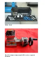
Page 18: ...TOOL TRAY The CNC toolpost setup manual will be sent as a separate document ...


