background image

-34-

M

A

INTE

N

A

N

CE

W1742W, W1742SW, W1754W, W1754SW (Mfd. Since 9/15)

Table.Height.Chain.&.Sprockets

Grease Type ........................... Lithium-Based NLGI#2

Frequency ..................... Every 160 Hours of Operation

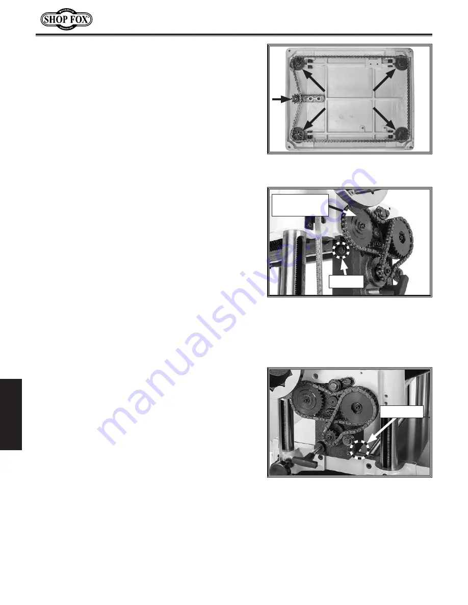
The table leadscrews are synchronized by the table height 

chain and sprockets located underneath the planer base 

(see 

Figure.36

). Use shop rags and mineral spirits to clean 

away debris and grime, then brush on a light coat of 

multi-purpose grease to the chain and sprockets.

Figure.36.

 Table height chain and 

sprockets as viewed from underneath base.

Drive.Chain.&.Sprockets

Grease Type ........................... Lithium-Based NLGI#2

Frequency ..................... Every 160 Hours of Operation

The infeed and outfeed rollers receive the transferred 

power from the cutterhead through the drive chain 

system on the right side of the machine, as shown in 

Figure.37

.

Remove the table height handwheel and the safety covers 

attached to the inside of the drive chain cover, then 

remove the cover to access these parts.

Use shop rags and mineral spirits to clean away any debris 

and grime, then brush on a light coat of multi-purpose 
grease to the chain and sprockets.

Gearbox.Oil

Oil Type ......................... ISO 320 or SAE 140 Gear Oil

Oil Amount ................................................ 20 Oz.

Frequency ................ After First 20 Hours, Then Yearly

Note:


SAE 85W-140 multi-weight gear oil may also be used 

as a substitute. DO NOT mix oil types!

Note:


We recommend that you replace the gearbox oil 

after the first 20 hours of operation. This is a normal 

break-in procedure and will help maximize the service life 

of the machine by flushing away any particles from the 

break-in and manufacturing process.

Although it is not necessary to remove the drive chain 

cover to access the fill and drain plugs, it is more 

convenient to do so (see 

Figures.37–38

). Add oil into the 

fill-plug hole until it just reaches the fill plug.

Figure.37.

 Location of drive chains, 

sprockets, and fill plug.

Fill Plug

Figure.38.

 Location of gearbox drain plug.

Drain Plug

Drive Chain

and Sprockets

Summary of Contents for W1742SW

Page 1: ...PLANERS Phone 360 734 3482 Online Technical Support techsupport woodstockint com COPYRIGHT JANUARY 2016 BY WOODSTOCK INTERNATIONAL INC WARNING NO PORTION OF THIS MANUAL MAY BE REPRODUCED IN ANY SHAPE...

Page 2: ...g grinding tool integrity and the usage of personal protective equipment The manufacturer will not be held liable for injury or property damage from negligence improper training machine modifications...

Page 3: ...blems 24 Depth of Cut 26 Bed Roller Height 27 Setting Feed Rate 28 Adjusting Replacing Knives W1742W W1754W 28 Adjusting Replacing Knives 28 Rotating Replacing Cutterhead Inserts W1742SW W1754SW 30 AC...

Page 4: ...ss metal liquids asbestos silica animal parts biohazards burning material ashes etc 5 Always disconnect power before servicing or cleaning 6 Do not expose to rain or wet areas 7 Keep hands long hair a...

Page 5: ...V Single Phase 60 Hz Full Load Current Rating 15A 20A Minimum Circuit Size 20A 30A Connection Type Cord Plug Power Cord Included Yes Power Cord Length 7 ft 7 ft Power Cord Gauge 12 AWG Plug Included Y...

Page 6: ...A Knife Type HSS Single Sided Solid N A HSS Single Sided Solid N A Knife Length 15 in N A 20 in N A Knife Width 1 in N A 1 in N A Knife Thickness 1 8 in N A 1 8 in N A Knife Adjustment Jack Screws N...

Page 7: ...tter understand the instructions in this manual To reduce your risk of serious injury or damage to the machine read this entire manual BEFORE using machine Feed Rate Control Knob Table Locks Bed Rolle...

Page 8: ...workpiece thicknesses One complete revolution moves the table approximately 1 16 C Feed Rate Control Knob Selects 20 FPM feed rate when pushed in and 16 FPM feed rate when pulled out D Table Locks Sec...

Page 9: ...ated Infeed Roller Pulls the workpiece toward the cutterhead C Chip Breaker Breaks off chips created by the cutterhead to prevent tear out and diverts the chips to the dust port D Chip Deflector Direc...

Page 10: ...gs or alcohol when tired or when distracted ELECTRICAL EQUIPMENT INJURY RISKS You can be shocked burned or killed by touching live electrical components or improperly grounded machinery To reduce this...

Page 11: ...duce accidental contact with moving parts or flying debris make sure they are properly installed undamaged and working correctly FORCING MACHINERY Do not force machine It will do the job safer and bet...

Page 12: ...ce before cutting Verify workpiece is free of nails staples loose knots or foreign material Workpieces with minor warping should be jointed first or planed with the cupped side facing the infeed table...

Page 13: ...vices that might operate at one time during normal operations The machine must be properly set up before it is safe to operate DO NOT connect this machine to the power source until instructed to do so...

Page 14: ...with all local codes and ordinances DO NOT modify provided plug For 240V Connection The machine must be properly set up before it is safe to operate DO NOT connect this machine to the power source unt...

Page 15: ...been carefully packaged for safe transportation If you notice the machine has been damaged during shipping please contact your authorized Shop Fox dealer immediately The following items are needed bu...

Page 16: ...sembly 1 H Feed Rate T Knob M8 1 25 1 I Hex Wrenches 3 4 5 6mm 1 Ea J Hex Wrench 8mm 20 Models Only 1 K Rubber Foot Assemblies 2 L Cap Screws M8 1 25 x 60 Rear Wheels 2 Lock Washers 8mm Rear Wheels 2...

Page 17: ...urfaces If your cleaner degreaser is effective the coating will wipe off easily Tip An easier way to clean off thick coats of rust preventative from flat surfaces is to use a PLASTIC paint scraper to...

Page 18: ...ions Extreme conditions for this type of machinery are generally those where the ambient temperature range exceeds 41 104 F the relative humidity range exceeds 20 95 non condensing or the environment...

Page 19: ...chine elevated by forklift Rear Wheel 1 of 2 x 2 Figure 13 Front feet installed with machine elevated by forklift Front Foot 1 of 2 2 While machine is elevated install rear wheels using 2 M8 1 25 X 60...

Page 20: ...down or work around them when leveling extension wings refer to Bed Roller Height on Page 27 for more information 3 W1742W W1742SW Only Remove two pre installed hex nuts from each table locking rod t...

Page 21: ...Dust Port W1742W W1742SW 400 CFM W1754W W1754SW 625 CFM Do not confuse this CFM recommendation with the rating of the dust collector To determine the CFM at the dust port you must consider these varia...

Page 22: ...so To remove the cover remove the seven cap screws that secure it to the planer To check gearbox oil level do these steps 1 Remove gearbox fill plug see Figure 20 2 Dip short end of a clean hex wrenc...

Page 23: ...egular operations Refer to Troubleshooting on Page 45 or call Tech Support for help Test Run TWIST To reset switch twist button clockwise Figure 21 Resetting the switch Serious injury or death can res...

Page 24: ...e of workpiece as it passes through planer Operator does not push or pull on workpiece If cut is too deep and bogs down planer operator immediately reduces depth of cut 6 Once workpiece is clear of ou...

Page 25: ...or individual components Excessive Warping Workpieces with excessive cupping bowing or twisting are dangerous to cut because they are unstable and often unpredictable when being cut DO NOT use workpie...

Page 26: ...as it leaves the outfeed end of the planer The best way to deal with snipe is by planing lumber longer than your intended work length and then cutting off the excess after planing is completed Cutting...

Page 27: ...olution Use a proper dust collection system adjust chip deflector in or out as necessary Lumber must be completely dry preferably kiln dried KD Air dried AD lumber must be seasoned properly and have n...

Page 28: ...3 Rotating the handwheel clockwise raises the table Although the correct depth of cut varies according to wood hardness and workpiece width we recommend the maximum depth of cut per pass be no more th...

Page 29: ...auges can be used but care must be taken to achieve accurate results Tools Needed Qty Hex Wrench 4mm W1742W W1742SW 1 Hex Wrench 3mm W1754W W1754SW 1 Hex Wrench 6mm 1 Rotacator 1 Figure 25 Bed roller...

Page 30: ...tion whenever working with or around cutterhead knives Wear heavy leather gloves to reduce risk of severe cuts To maintain accurate and consistent planing results we do not recommend sharpening knives...

Page 31: ...W1754W cutterhead components Figure 28 Knife setting jig correctly positioned over knife Center Pad Gib Bolt Knife Setting Jig Knife Figure 29 W1742W W1754W jack screw access hole in cutterhead Jack S...

Page 32: ...5 Remove Torx screw and insert then clean all dust and debris from both parts and cutterhead pocket Note Proper cleaning of insert Torx screw and cutterhead pocket is critical to achieving a smooth fi...

Page 33: ...er adjustments Perfect for adjusting infeed outfeed rollers pressure bars chip breakers and bed rollers Also a great setup tool for other machines Accurate to 0 001 Indicator rotates 360 W1834 20 Blad...

Page 34: ...replace V belts Page 35 Clean vacuum dust buildup from inside cabinet and off motor Lubricate table height worm gear Page 33 Lubricate table height chain sprockets Page 34 Lubricate drive chain sprock...

Page 35: ...Equivalent Oil Amount Thin Coat Grease Type NLGI 2 Equivalent Frequency Every 40 Hours of Operation The table rides on the columns and is moved by the rotation of the leadscrews inside the columns Loo...

Page 36: ...inside of the drive chain cover then remove the cover to access these parts Use shop rags and mineral spirits to clean away any debris and grime then brush on a light coat of multi purpose grease to t...

Page 37: ...ms make sure the V belts are always properly tensioned and in good condition If the V belts are worn cracked or damaged replace them Always replace the V belts with a matched set of three or belt tens...

Page 38: ...tly tensioned Tensioning Table Height Chain The table height chain transfers movement from the elevation handwheel to the columns that control table height The chain drive can be adjusted to remove sl...

Page 39: ...tance Below Knife Insert at BDC Figure 43 A Infeed Roller 0 020 B Chip Breaker 0 020 C Pressure Bar 20 Models Only 0 008 D Outfeed Roller 0 040 Using a Rotacator Tools Needed Qty Phillip s Screwdriver...

Page 40: ...see Figure 45 to adjust height of infeed roller bushing block until Rotacator dial shows 0 020 which is the recommended distance for infeed roller below cutterhead 9 Repeat Steps 7 8 on left hand side...

Page 41: ...cing Knives on Page 28 for detailed instructions 3 DISCONNECT MACHINE FROM POWER 4 Lower bed rollers below table surface refer to Bed Roller Height on Page 27 for detailed instructions 5 Place wood bl...

Page 42: ...sert Feeler Gauge Here Figure 50 Feeler gauge location for adjusting chip breaker height when using wood blocks Insert Feeler Gauge Here Jam Nut Set Screw Cross Bar Figure 51 Example of feeler gauge l...

Page 43: ...n adjusting the roller spring tension keep the following in mind If you are planing milled lumber with a relatively consistent surface use less spring tension If you are planing rough lumber with inco...

Page 44: ...p do these steps 1 DISCONNECT MACHINE FROM POWER 2 Remove dust hood top cover and belt cover Figure 53 Chip deflector and securing flange bolts Chip Deflector Flange Screws 1 of 3 3 Use cutterhead pul...

Page 45: ...age If any of the fingers are damaged the device must be replaced before using the machine Do not apply oil or other lubricants to the anti kickback fingers that will attract dust and restrict free mo...

Page 46: ...king pulley alignment 2 Remove both cabinet covers and belt cover then use straightedge to check pulley alignment as shown in Figure 56 If pulleys are not in same plane loosen cap screw or hex bolt th...

Page 47: ...s poor contacts 12 Motor bearings at fault 1 Reduce feed rate depth of cut 2 Only cut wood ensure moisture is below 20 3 Allow motor to cool reset overload if necessary and reduce depth of cut Contact...

Page 48: ...2 Take a smaller depth of cut Reduce cutting depth when planing hard woods 3 Slow down feed rate 4 Adjust both sides of chipbreaker to correct height 5 Replace affected knife Page 28 or have it sharp...

Page 49: ...g but it may not match your machine Always use the wiring diagram inside the motor junction box CAPACITORS INVERTERS Some capacitors and power inverters store an electrical charge for up to 10 minutes...

Page 50: ...37 220V Pedestal Mounted ON OFF Switch O 13NO Power Indicator Light AD 11 25 40 1G 220V R O 12 GND NEMA 6 20 Plug Hot Ground Hot G 14NO A B A B Motor GND Start Capacitor CBB60 40MFD 450VAC Run Capacit...

Page 51: ...A Start Button GLY37 220V Stop Button GLY37 220V Pedestal Mounted ON OFF Switch O GND 13NO Power Indicator Light AD 11 25 40 1G 220V R O G GND Start Capacitor CBB60 40MFD 450VAC Run Capacitor CD60 300...

Page 52: ...3 13 13 14 15 17 18 19 24 25 26 27 28 29 10 30 17 31 32 33 34 35 36 37 37 39 40 41 44 17 38 45 46 60 45 47 49 63 63 51 56 56 57 58 42 59 61 62 64 64 50 66 68 69 70 71 72 31 73 33 34 63 63 50 74 76 77...

Page 53: ...065 OUTFEED ROLLER 22 X1742W022 KNIFE SETTING JIG SHAFT W1742W 66 X1742W066 BUSHING BLOCK PLATE 23 X1742W023 CAP SCREW M6 1 X 20 67 X1742W067 UPPER SHAFT 24 X1742W024 GEARBOX COVER 68 X1742W068 MIDDLE...

Page 54: ...NG ROD 103 X1742W103 FLAT WASHER 5MM 113 X1742W113 LOCK SLEEVE 104 X1742W104 CAP SCREW M5 8 X 10 114 X1742W114 BALL BEARING 6201ZZ 105 X1742W105 GIB 115 X1742W115 BED ROLLER 106 X1742W106 STAR KNOB M1...

Page 55: ...05 X1742W205 SECONDARY LEADSCREW 220 X1742W220 FENDER WASHER 6MM 206 X1742W206 EXT RETAINING RING 20MM 221 X1742W221 CAP SCREW M5 8 X 12 207 X1742W207 HEX NUT M8 1 25 222 X1742W222 CAP SCREW M8 1 25 X...

Page 56: ...X1742W322 COMPRESSION SPRING 0 5 X 5 X 20 2 306 X1742W306 FENDER WASHER 6MM 323 X1742W323 SHAFT 307 X1742W307 FLANGE BOLT M6 1 X 12 324 X1742W324 OIL SEAL 25 X 47 X 7 308 X1742W308 BALL BEARING 6201Z...

Page 57: ...W404 FLAT WASHER 10MM 417 X1742W417 CHAIN 06B 1 X 64 405 X1742W405 CHAIN TENSIONER 418 X1742W418 SHAFT 406 X1742W406 CHAIN TENSIONER SHAFT 419 X1742W419 SPACER 16 X 25 X 2MM 407 X1742W407 CHAIN TENSIO...

Page 58: ...6 517 503 519 513 520 522 521 523 510 526 534 533 532 527 528 529 527 531 528 527 530 525 506 537 509 536 535 538 503 509 511 511 524 512 507 518 502 501 504 4 504 1 504 2 504 5 504 7 504 3 504 2 504...

Page 59: ...5 1 X1742W545 1 MAG SWITCH BOX 507 X1742W507 MOTOR MOUNT PLATE 545 2 X1742W545 2 CONTACTOR TECO CU 11 220V 508 X1742W508 LOCK COLLAR 545 3 X1742W545 3 OL RELAY TECO RHU 10 1 11 3 16A 509 X1742W509 LOC...

Page 60: ...60 77 79 72 63 71 72 60 58 59 62 75 42 43 44 45 32 28 19 10 36 37 36 37 44 80 37 48 78 72 34 46 47 57 55 56 3 8 18 18 20 18 24 25 53 26 18 29 18 18 35 27 18 30 27 18 38 39 40 41 41 38 48 63 54 27 16 1...

Page 61: ...SHAFT W1754W 69 X1754W069 ANTI KICKBACK FINGER 23 X1754W023 EXT RETAINING RING 10MM W1754W 70 X1754W070 E CLIP 15MM 24 X1754W024 CAP SCREW M6 1 X 20 71 X1754W071 LOCKING ROD BRACKET 25 X1754W025 GEARB...

Page 62: ...SET SCREW M6 1 X 16 103 X1754W103 CAP SCREW M5 8 X 10 113 X1754W113 CAP SCREW M6 1 X 16 104 X1754W104 BED ROLLER 114 X1754W114 TABLE EXTENSION WING 105 X1754W105 BALL BEARING 6201ZZ 115 X1754W115 LOCK...

Page 63: ...54W205 SECONDARY LEADSCREW 221 X1754W221 CHAIN TENSION BRACKET 206 X1754W206 PRIMARY LEADSCREW 222 X1754W222 SPROCKET 10T 207 X1754W207 LEADSCREW NUT 223 X1754W223 EXT RETAINING RING 15MM 208 X1754W20...

Page 64: ...X1754W322 COMPRESSION SPRING 0 5 X 5 X 20 2 306 X1754W306 FENDER WASHER 6MM 323 X1754W323 SHAFT 307 X1754W307 FLANGE BOLT M6 1 X 12 324 X1754W324 OIL SEAL 25 X 47 X 7 308 X1754W308 BALL BEARING 6201Z...

Page 65: ...W404 FLAT WASHER 10MM 417 X1754W417 CHAIN 06B 1 X 68 405 X1754W405 CHAIN TENSIONER 418 X1754W418 SHAFT 406 X1754W406 CHAIN TENSIONER SHAFT 419 X1754W419 SPACER 16 X 25 X 2MM 407 X1754W407 CHAIN TENSIO...

Page 66: ...3 515 512 516 517 518 503 519 513 520 522 521 523 510 526 534 533 532 527 528 529 527 531 528 527 530 525 506 537 509 536 535 538 503 509 511 511 524 512 504 4 504 1 504 2 504 5 504 7 504 3 504 2 504...

Page 67: ...545 1 X1754W545 1 MAG SWITCH BOX 507 X1754W507 MOTOR MOUNT PLATE 545 2 X1754W545 2 CONTACTOR TECO CU 18 220V 508 X1754W508 LOCK COLLAR 545 3 X1754W545 3 OL RELAY TECO RHU 10 1 17 5 21 5A 509 X1754W509...

Page 68: ...tant material 1 5 16 Labels marked have changed since last sending Only shift gearbox when planer is running Neutral 20 FPM 16 FPM Add SAE 30 oil every 24 hours of operation NOTICE OWNER S MANUAL FOR...

Page 69: ...W1742W SW W1754W SW Mfd Since 9 15...

Page 70: ...tape along edges please do not staple Fold along dotted lIne Fold along dotted lIne Woodstock international inc p o box 2309 bellingham Wa 98227 2309 place stamp Here...

Page 71: ...he scope of Woodstock International Inc s warranty then the original owner must bear the cost of storing and returning the product This is Woodstock International Inc s sole written warranty and any a...

Page 72: ...High Quality Machines and Tools Woodstock International Inc carries thousands of products designed to meet the needs of today s woodworkers and metalworkers Ask your dealer about these fine products...

Reviews: