background image

-35-

M1048 10" x 18" Metal Cutting Bandsaw

PA

RT

S

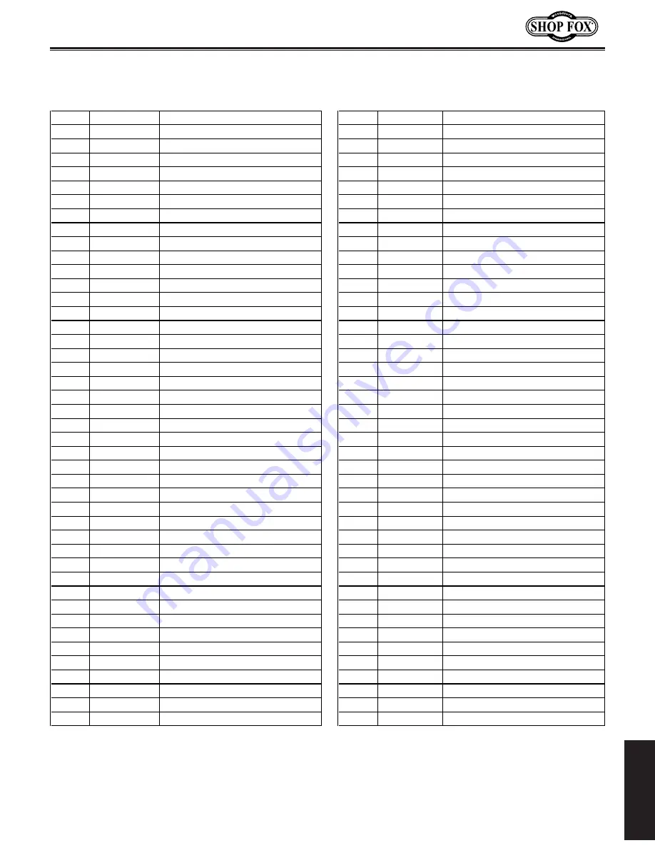
Blade Guides Parts List

REF

PART

#

DESCRIPTION

REF

PART

#

DESCRIPTION

101

XM1048101

SLIDE

SET

157

XM1048157

PLASTIC

BUSHING

101-1

XM1048101-1 SLIDE

158

XPSB04M

CAP

SCREW

M6-1

X

10

101-2

XM1048101-2 SPECIAL

SET

SCREW

159

XPLW02

LOCK

WASHER

1/4

101-3

XPN10

HEX

NUT

7/16-20

160

XM1048160

HEX

NUT

M8

101-4

XPW04M

FLAT

WASHER

10MM

161

XPLW01

LOCK

WASHER

5/16

101-5

XPSB134M

CAP

SCREW

M10-1.5

X

65

163

XM1048163

BLADE

GUARD

101-6

XM1048101-6 DISC

SPRING

164

XM1048164

BLADE

LABEL

101-7

XM1048101-7 INDICATOR

DIAL

167

XPLW02

LOCK

WASHER

1/4

101-8

XM1048101-8 BEARING

51204

168

XPSB04M

CAP

SCREW

M6-1

X

10

101-9

XPW01

FLAT

WASHER

1/2

169

XM1048169

SCALE

101-10 XM1048101-10 SPECIAL

SCREW

170

XM1048170

RIVET

101-11 XM1048101-11 SCALE

171

XPSB77M

CAP

SCREW

M12-1.75

X

30

101-12 XPS05M

PHLP

HD

SCR

M5-.8

x

8

172

XPSS09M

SET

SCREW

M8-1.25

X

20

101-13 XPB32M

HEX

BOLT

M10-1.5

x

25

173

XM1048173

COLUMN

101-14 XPLW06M

LOCK

WASHER

10MM

174

XPSB84M

CAP

SCREW

M10-1.5

X

35

101-15 XM1048101-15 GIB

175

XPW04M

FLAT

WASHER

10MM

101-16 XM1048101-16 BRACKET

176

XPRP49M

ROLL

PIN

5

X

25

102

XPRP49M

ROLL

PIN

5

X

25

177

XM1048177

LEFT

COLUMN

SUPPORT

103

XM1048103

COLLAR

178

XPSB05M

CAP

SCREW

M8-1.25

X

50

104

XM1048104

LEADSCREW

179

XPLW04M

LOCK

WASHER

8MM

105

XPK20M

KEY

5

X

5

X

15

180

XPLW01

LOCK

WASHER

5/16

106

XM1048106

HANDWHEEL

&

HANDLE

181

XM1048181

SUPPORT

SEAT

107

XM1048107

COMPRESSION

SPRING

182

XM1048182

ADJ

FIXING

PLATE

(IDLER)

108

XPRP30M

ROLL

PIN

5

X

50

183

XPLW02

LOCK

WASHER

1/4

109

XM1048109

BRACKET

184

XPSB02M

CAP

SCREW

M6-1

X

20

110

XM1048110

SHAFT

185

XPN03M

HEX

NUT

M8-1.25

141

XPSB72M

CAP

SCREW

M10-1.5

X

30

186

XPSS09M

SET

SCREW

M8-1.25

X

20

142

XPLW06M

LOCK

WASHER

10MM

187

XM1048187

BLADE

ADJUSTABLE

KNOB

143

XM1048143

IDLER

WHEEL

BOX

188

XPW04M

FLAT

WASHER

10MM

144

XPSB130M

CAP

SCREW

M10-1.5

X

16

189

XM1048189

ARM

(LEFT)

145

XM1048145

TENSION

LABEL

190

XM1048190

GIB

146

XM1048146

RIVET

191

XM1048191

HOSE

CLAMP

147

XPS68M

PHLP

HD

SCR

M6-1

X

10

192

XPS05M

PHLP

HD

SCR

M5-.8

X

8

148

XM1048148

BRACKET

193

XM1048193

ARM

(RIGHT)

149

XPSB77M

CAP

SCREW

M12-1.75

X

30

194

XPW04M

FLAT

WASHER

10MM

150

XPSB06M

CAP

SCREW

M6-1

X

25

195

XPSB71M

CAP

SCREW

M10-1.5

X

60

151

XM1048151

BUSHING

200

XM1048200

BEARING

SPACER

152

XM1048152

IDLER

WHEEL

ASSY

203

XM1048203

BEARING

BRACKET

(IDLER)

152-3

XPB70M

HEX

BOLT

M10-1.5

X

16

204

XPSS20M

SET

SCREW

M8-1.25

X

8

152-4

XPW04M

FLAT

WASHER

10MM

205

XM1048205

CARBIDE

GUIDE

153

XPSB11M

CAP

SCREW

M8-1.25

X

16

206

XPSB02M

CAP

SCREW

M6-1

X

20

154

XM1048154

HANDLE

207

XM1048207

ECCENTRIC

SHAFT

SET

155

XM1048155

SPEED

INDICATOR

LABEL

208

XM1048208

BEARING

SHAFT

ASSY

156

XM1048156

IDLER

WHEEL

COVER

209

XM1048209

MICRO

CONTROL

BLOCK

Summary of Contents for M1048

Page 1: ...ine Technical Support tech support shopfox biz COPYRIGHT JULY 2006 BY WOODSTOCK INTERNATIONAL INC REVISED AUGUST 2007 TR WARNING NO PORTION OF THIS MANUAL MAY BE REPRODUCED IN ANY SHAPE OR FORM WITHOU...

Page 2: ......

Page 3: ...structions for Bandsaws 8 ELECTRICAL 9 220V Operation 9 Extension Cords 9 Grounding 9 SETUP 10 Unpacking 10 Inventory 10 Machine Placement 11 Cleaning Machine 11 Mounting to Shop Floor 12 Moving Placi...

Page 4: ...n 24 SERVICE 26 Troubleshooting 26 Blade Change 28 Blade Tension Tracking 29 Blade Guide Bearings 30 Squaring Blade to Table 31 Electrical Components 32 Model M1048 220V Wiring Diagram 33 Blade Guides...

Page 5: ...y claims INTRODUCTION If you need the latest edition of this manual you can download it from http www shopfox biz If you have comments about this manual please contact us at Woodstock International In...

Page 6: ...e 1 M1048 Machine Identification A Blade Tension Handwheel B Lift Handle C Vise Handwheel D Coolant Drip Pan E Work Stop F Pulley Cover G Control Panel H Blade Guide Scale I Blade Guide Knob J Coolant...

Page 7: ...switch that turns the motor and coolant pump OFF at the bottom of the cut C START Button Turns the motor ON and begins the sawing action D Power Light When lit indicates that system is energized and m...

Page 8: ...in moving parts Wear protective hair covering to contain long hair and wear non slip footwear 6 NEVER OPERATE MACHINERY WHEN TIRED OR UNDER THE INFLUENCE OF DRUGS OR ALCOHOL Be mentally alert at all...

Page 9: ...ecking for keys and adjusting wrenches before turning machinery ON 18 CHECK FOR DAMAGED PARTS BEFORE USING MACHINERY Check for binding and alignment of parts broken parts part mounting loose bolts and...

Page 10: ...asses to protect eyes and always disconnect from power 5 WORKPIECE HANDLING Always support the workpiece with table vise or other support fixture Flag long pieces to avoid a tripping hazard Never hold...

Page 11: ...s should you connect your machine to an ungrounded power source or electrocution or severe shock could occur 220V Operation The Model M1048 is wired for 220V operation Always connect this machine to a...

Page 12: ...ed on the machine Make sure to check the machine when you use this inventory list Box Inventory Figure 4 Qty A Model M1048 Metal Cutting Bandsaw 1 Hardware and Tools Not Shown Chip Tray 1 Triagle Scre...

Page 13: ...arts of your Bandsaw are coated with a waxy grease that protects them from corrosion during shipment Clean this grease off with a solvent cleaner or citrus based degreaser DO NOT use chlorine based so...

Page 14: ...methods for anchoring an object to a concrete floor We suggest you research the many options and methods for mounting your machine and choose the best that fits your specific appli cation Mounting to...

Page 15: ...e crate Shipping Bracket Figure 9 Shipping bracket The bracket in Figure 9 has been installed to keep the saw in alignment during shipping Remove it before using your saw Store it for safe keeping in...

Page 16: ...st the feed stop bolt do these steps 1 Adjust the feed stop bolt and jam nut Figure 12 so the bandsaw blade teeth are 1 16 below the vise table surface The adjustments listed below have been performed...

Page 17: ...andsaw to power 5 Raise the bandsaw and close the feed control knob to keep the saw in place 6 Start the bandsaw while keeping your finger near the EMERGENCY STOP OFF button Figure 13 at all times dur...

Page 18: ...ur safety should come first READ and understand this entire instruc tion manual before using this machine Serious personal injury may occur if safety and operational information is not understood and...

Page 19: ...see Figure 16 3 With the rear vise jaw making contact with the posi tive stop tighten the rear vise jaw and re check the angle 4 Loosen the rear vise lock handle and swing the rear jaw until it reach...

Page 20: ...keeping the blade from twisting and drift ing off of the cut line To adjust the rear blade guide arm Loosen the knob shown in Figure 18 and slide the rear blade guide as close to the workpiece as poss...

Page 21: ...tact the blade manufacturer To select the correct blade TPI do these steps 1 Measure the material thickness This mea surement is the length of cut taken from where the tooth enters the workpiece sweep...

Page 22: ...ns in FPM 114 196 288 377 Motor Drive Wheel ENTANGLEMENT HAZARD DO NOT operate bandsaw with pulley cover open Personal injury could occur The speed at which the saw blade will cut through a workpiece...

Page 23: ...ou will over heat the pump and void your warranty Coolant System This bandsaw has a built in coolant system that extends the life of your bandsaw blades by lowering the tempera ture of the blade and w...

Page 24: ...ricate the blade and flush the chips away so they do not stick to the blade If the chips build up on the blade eventually they will bind and skid in the next cut break ing blade teeth and damaging the...

Page 25: ...e cut end it could be very hot Support long pieces so they won t fall when cut and flag the ends to alert passers by of potential dan ger Adjust the blade guides as close as possible to the workpiece...

Page 26: ...off metal chips with a brush or use a shop vacuum to remove the chips Keeping metal chips away from bandsaw mechanisms is important to making sure that your bandsaw lasts a long time This machine is e...

Page 27: ...ce every year Use a high quality ISO 68 or SAE 90 gear oil To change the gear oil do these steps 1 Run the bandsaw for a couple of minutes to warm up the oil in the gearbox 2 DISCONNECT THE BANDSAW FR...

Page 28: ...main power supply is switched ON 7 Replace faulty ON OFF switch 8 Check for broken wires or disconnected corroded connections and repair replace as necessary 9 Test repair replace Machine stalls or i...

Page 29: ...the material 5 The blade is twisted 6 The blade is slipping on the wheels 1 Refer to Changing Blade Speed on Page 20 and adjust as required 2 Refer to Blade Selection on Page 19 and adjust as require...

Page 30: ...then out of the blade guide roller bearings 7 Install the new blade into front and rear blade guide roller bearings as shown in Figure 33 then around the bottom and top wheels Note It is sometimes po...

Page 31: ...is used properly Do not attempt to adjust track ing until the blade is properly tensioned To adjust the blade tracking on the bandsaw do these steps 1 Loosen or tighten the tracking set screw in Figur...

Page 32: ...own until it lightly touches the back of the blade The blade guide roller bearings also need to be adjusted The front bearing is mounted on an eccentric and can be easily adjusted to suit the blade th...

Page 33: ...le and blade as shown in Figure 39 3 Check for gaps along several points of the blade length between the two blade guides Set the machinist square between the blade teeth for a more accurate reading 4...

Page 34: ...mit switch SQ1 Figure 44 Pump motor wiring and capacitor M2 Figure 43 Control panel wiring Figure 42 Junction box M1 SB4 SB1 SB3 L Electrical Components Figure 45 M1048 Contactor relay electrical box...

Page 35: ...rical work ser vice or adjustment Model M1048 220V Wiring Diagram OFF LEGEND M Motor KM1 Contactor Main Motor KM2 Pump Motor Relay KM1 Thermal Relay Main Motor L Indicator Lamp SB1 Emergency Stop Butt...

Page 36: ...34 M1048 10 x 18 Metal Cutting Bandsaw PARTS Blade Guides Parts Breakdown...

Page 37: ...9 XPLW04M LOCK WASHER 8MM 105 XPK20M KEY 5 X 5 X 15 180 XPLW01 LOCK WASHER 5 16 106 XM1048106 HANDWHEEL HANDLE 181 XM1048181 SUPPORT SEAT 107 XM1048107 COMPRESSION SPRING 182 XM1048182 ADJ FIXING PLAT...

Page 38: ...36 M1048 10 x 18 Metal Cutting Bandsaw PARTS Drive Wheel Parts Breakdown...

Page 39: ...16 277 XPSB02M CAP SCREW M6 1 X 20 234 XPN03M HEX NUT M8 1 25 278 XPN03M HEX NUT M8 1 25 235 XPSS01M SET SCREW M6 1 X 10 279 XPSS01M SET SCREW M6 1 X 10 236 XM1048236 PIVOT SHAFT 280 XM1048280 BEARING...

Page 40: ...38 M1048 10 x 18 Metal Cutting Bandsaw PARTS Main Parts Breakdown...

Page 41: ...12 364 XM1048364 BRACKET 415 XM1048415 NAME PLATE 365 XPSB48M CAP SCREW M6 1 X 35 416 XPS70M PHLP HD SCR M5 1 X 8 366 XPSB13M CAP SCREW M8 1 25 X 30 417 XM1048417 COLUMN 367 XM1048367 DISTANCE SET ROD...

Page 42: ...SHER 1 4 474 XPW07 FLAT WASHER 5 16 449 XPS07 PHLP HD SCR 1 4 20 X 3 8 475 XM1048475 CYLINDER ASSY 450 XM1048450 COUPLER PT 1 2 X 1 4 476 XM1048476 PIVOT SHAFT 451 XM1048451 HOSE 3 4 X 1 5 477 XLABEL...

Page 43: ...The owner of this machine MUST maintain the original location and readability of all labels on this machine If any label is removed or becomes unreadable REPLACE that label before allowing the machine...

Page 44: ...d from causes not within the scope of Woodstock International Inc s warranty then the original owner must bear the cost of storing and returning the product This is Woodstock International Inc s sole...

Page 45: ...ine represents a good value _____ Yes ____ No 5 Would you recommend Shop Fox products to a friend _____ Yes ____ No 6 What is your age group _____ 20 29 ____ 30 39 ____ 40 49 _____ 50 59 ____ 60 69 __...

Page 46: ...TAPE ALONG EDGES PLEASE DO NOT STAPLE FOLD ALONG DOTTED LINE FOLD ALONG DOTTED LINE WOODSTOCK INTERNATIONAL INC P O BOX 2309 BELLINGHAM WA 98227 2309 Place Stamp Here...

Page 47: ......

Page 48: ......

Reviews: