41
Parts
11
Parts
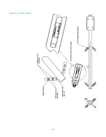
Bay components
Table 4. Components, 6842 bay without de-icers (per antenna bay)
Part Number
Description
Qty.
1. 99718-G504
Bay assembly with arms & mounting bracket
1
2. 01/4-20SS028HM
•
Screw, hex head 1/4-20 x 1-3/4" SS
10
3. 01/4-20SSN
•
Nut, 1/4-20 locking SS
10
4. 01/4SSF
•
Washer, flat 1/4" regular SS
21
5. 99744-G501
•
Arm weldment
4
6. 1/4SSS
Washer, split lock 1/4" SS
1
7. 01/4-20SS008HM
Screw, hex head 1/4-20 x 1/2" SS
1
8. 99745-01 formed
Feedstrap, formed
1
9. G58NUT
Nut, hex 5/8-11 heavy galvanized
12
10. GR58FW
Washer, flat 5/8 heavy galvanized
12
11. G58LW
Washer, split lock 5/8" galvanized
8
12. G58R-10
Rod, full threaded 5/8-11 galvanized
4
13. DCP
Clamp half, 5.75" bolt spacing
2
Table 5. Components, 6842 bay with de-icers (per antenna bay)
Part Number
Description
Qty.
14. 99718-G504
Bay assembly with arms, mounting bracket,
and de-icers
1
2. 01/4-20SS028HM
•
Screw, hex head 1/4-20 x 1-3/4" SS
10
3. 01/4-20MSN
•
Nut, 1/4-20 locking SS
10
4. 01/4SSF
•
Washer, flat 1/4" regular SS
21
5. 99744-G501
•
Arm weldment
4
15. 97353-11
•
Element, de-icer heater
16. 51299-G506
•
Pigtail, bay deicer
1
6. 1/4SSS
Washer, split lock 1/4" SS
1
7. 01/4-20SS016HM
Screw, hex head 1/4-20 x 1" SS
1
8. 99745-01 formed
Feedstrap, formed
1
9. G58NUT
Nut, hex 5/8-11 heavy galvanized
12
10. GR58FW
Washer, flat 5/8 heavy galvanized
12
11. G58LW
Washer, split lock 5/8" galvanized
8
12. G58R-10
Rod, full threaded 5/8-11 galvanized
4
13. DCP
Clamp half, 5.75" bolt spacing
2
Summary of Contents for 6842
Page 4: ......
Page 8: ......
Page 11: ...3 Preparation Figure 1 Tower layout single bay antenna ...
Page 12: ...Preparation 4 Figure 2 Tower layout two bay antenna ...
Page 13: ...5 Preparation Figure 3 Tower layout three bay antenna ...
Page 14: ...Preparation 6 Figure 4 Tower layout four bay antenna ...
Page 15: ...7 Preparation Figure 5 Tower layout five bay antenna ...
Page 16: ...Preparation 8 Figure 6 Tower layout six bay antenna ...
Page 17: ...9 Preparation Figure 7 Tower layout eight bay antenna ...
Page 18: ...Preparation 10 Figure 8 Top mounted installation ...
Page 22: ......
Page 26: ......
Page 32: ......
Page 37: ...29 Connecting the Antenna 2 bay Figure 17 Two way power divider mounted and connected ...
Page 38: ......
Page 46: ...Startup 38 Figure 21 Apply the signal ...
Page 48: ......
Page 51: ...43 Parts Figure 23 Endseal radome components ...
Page 58: ......
Page 60: ...52 Figure A 1 22 Feed Strap with Endseal Radome Deicer ...
Page 61: ...53 Figure A 2 6842 Exploded View with Endseal Radome ...
Page 62: ...54 Figure A 3 Bay Arm Stickers ...
Page 63: ...55 Figure A 4 Power Divider Mount Detail ...
Page 64: ......


