13
Installing the De-icer System (if applicable)
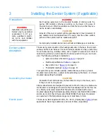
De-icer installation
Installing the de-icer
harness
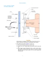
a. Install the main de-icer harness with its bay junction boxes as shown in
on page 14. Connect the leads from each
bay’s de-icer pigtail to the main harness in that bay’s junction box as shown.
CAUTION
It is important to ground both the tower junction box and the control
box, as shown in the schematic diagrams.
b. Furnish a tower junction box as shown schematically in
to connect the
antenna’s de-icer harness to the main power.
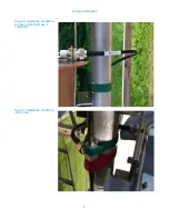
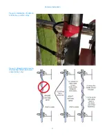
c. Using tie-wraps, secure the entire length of the de-icer harness to the RF
feedline at about 24" (60 cm) intervals. Run the ten-foot de-icer pigtail along
a feedline mount to the tower junction box and secure it to the mount and
the tower.
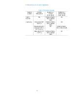
Table 4. De-Icer specifications
Heater Leg
Resistance,
Heater Leg
(T1 or T2)
Current Draw,
amps
1-Bay
203
0.6
2-Bay
101
1.2
3-Bay
68
1.8
4-Bay
51
2.4
5-Bay
41
3.0
6-Bay
34
3.6
7-Bay
29
4.1
8-Bay, single circuit
25
4.7
CAUTION
Shively Labs's de-icer
control box, Model 94068,
is designed for interior
installation only.


