background image


We advise the use of non slip protective gloves throughout 

the assembly process. 


We advise the use of steel capped protective footwear 

throughout the assembly process. 


We advise the use of protective headwear and safety     

goggles throughout the assembly process. 


Where a ladder is in use another person must hold the    

ladder. 


Do not attempt to work in windy conditions. 


We advise the use of a scaffold tower when fitting the roof, 

for felting or if you cannot reach from the ground. 


Do not allow children near the tools and work area. 


Follow any safety precautions quoted by the manufacturer 

for any equipment you use.  


We advise that you use a helper to hold the glass in position 

whilst  you nail the beading in place. 


Check all parts before assembly. 


Only use child and animal safe wood preservative. 


Do not use creosote. 


Allow the wood preservative to fully dry before use. 


Regularly check the building for wear and tear. 

Getting

 Started….. 

GB 

IE 

EVERY PRECAUTION IS TAKEN TO ENSURE THAT YOUR BUILDING HAS NO     
ELEMENT  INCORRECTLY PLACED OR POSSIBLY HAZARDOUS, HOWEVER 
PRIOR TO USE PLEASE CHECK ALL  SURFACES FOR THE FOLLOWING: 


(1) 

RAISED GRAIN, SPLINTERS: Sand down timber to smooth finish 

(2) 

NAIL/SCREW/PIN HEADS PROUD: Tap home to be flush with surface of 
timber 

(3) 

DAMAGED SCREW HEADS RESULTING IN SHARP SPLINTERS OF  

(4) METAL: 

Replace 

(5) 

SHARP ENDS OF NAILS/ SCREWS/ PINS PROTRUDING THROUGH THE 
PANEL: Remove and reposition 

(6) 

ENSURE ALL PARTS ARE SECURED AGAINST REASONABLE FORCE: 
Remove and refit 

(7) 

ENSURE THERE ARE NO LOOSE PARTS: Remove and refit/discard 

Important!  

Safety 

IMPORTANT ! 

For your safety please read 

carefully the safety warnings   

Check that you have noted all the following instructions: 

03


Summary of Contents for 10x6 Sun Pent

Page 1: ...10x6 Sun Pent Version 3 23 01 2020 Julian Shepherd These instructions are for your safety Please read through them thoroughly before use PLEASE KEEP THIS LEAFLET FOR FUTURE REFERENCE...

Page 2: ...j zyku prosimy o wys anie maila lub pisa na adres podany poni ej RUS TR Ba ka bir dilde talimatlar veya bir kopyas n bir kopyas i in bir e posta g nderebilir veya a a daki adrese yaz n z EN For a copy...

Page 3: ...bly Only use child and animal safe wood preservative Do not use creosote Allow the wood preservative to fully dry before use Regularly check the building for wear and tear Getting Started GB IE EVERY...

Page 4: ...y prior to or after assembly The building must have been re treated and re sealed annually NOTE Wood is a natural product and therefore the following are excluded from the warranty Colour change Warpi...

Page 5: ...6 golden rules of maintenance 1 Timber widely recycled 2 Metal fixings widely recycled 3 Glass widely recycled 4 Roofing felt not currently recycled packaging Building 1 Ensure your base is level and...

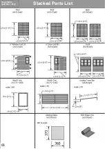
Page 6: ...Stacked Parts List Description part No Qty 06...

Page 7: ...Fascia Bag Parts List Description part No Qty 07...

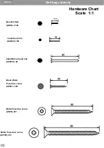
Page 8: ...0023 x 140 8mmFelt Nail A0025 x 42 40mmRound head nail A0035 x81 60mmPosi drive screw Nail bag contents Description part No QTY 13mm A0031 x04 Posi drive screw Black 25mm A0024 x128 16mm Panel Pin A00...

Page 9: ...4 You will need Hammer Spirit level Ladder 1mm 5mm 8mm drill bit Drill Tape measure Ruler Sand paper Gloves Saw Pencil Goggles A helper for some tasks Screwdriver Sharp knife Masking tape When you see...

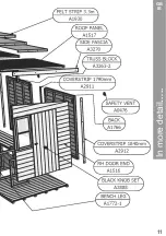
Page 10: ...10 In more detail GB IE...

Page 11: ...11 In more detail GB IE...

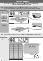
Page 12: ...ve the transport blocks from the bottom of the panels by gently tapping one end with a hammer 12 REMOVE TRANSPORT BLOCKS 01 Floor panel A1512 x02 GB IE Drill ONE of the A1512 floor panels only at the...

Page 13: ...in the LH End panel A1513 only The LH Back panel A1766 is positioned first on top oft he Floor A1512 and goes into the corner Notch to the middle of the back The cladding overlaps the floor Push the...

Page 14: ...n the LH Back panel A1766 only The RH Back panel A1766 is pushed up to the other back panel and fixed together Both the back and front panels fill the entire floor length 04 RH Back Panel A1766 x01 5...

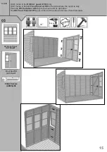
Page 15: ...e LH Front Panel A1765 in the side where the notch is only Push the RH End panel A516 up to the back and fix as before The RH Front Panel A1765 goes in front of the side and screws from that panel 05...

Page 16: ...Front panel A1765 fits in front of the side The front panel is fixed using the holes drilled in the last step 06 GB IE Unlock the door and fit the Black Knob set A2888 07 60mm Screws A0035 x06 25mm Bl...

Page 17: ...block is fitted 44mm below the notch and the back one 39mm Drill a hole half way in to the blocks 8mm then through with a 5mm drill And fix with 80mm screws Place the truss bars on the top and drill a...

Page 18: ...end of the support frame Position the Roof A1517 so the support frame sits on top of the ends frame and the slot goes over the cladding Centralise the roof and fix through the holes just drilled Mark...

Page 19: ...A0035 x13 Roof Panel A1517 x01 Drill and fix the second roof panel as with the previous step Inside the building where the roofs meet drill through one sides framework and fix together with 3 screws...

Page 20: ...to hold the felt in position nail the sides to the wall with 4 nails each and at the bottom nail at approximately 100mm centres The next piece overlaps the lower piece Measure the roof and work out a...

Page 21: ...GB IE Fix the panels to the floor with 2x60mm screws per panel using the holes previously drilled NOTE make sure the screws go into the floor bearers 13 40mm Nails A0025 x24 60mmScrew A0035 x12 56mm F...

Page 22: ...is flush with the felt at the corner Drill and fix the Fascia s with 4 nails each side Drilling prevents splitting The two front fascia A2915 fits across the end fascia s Drill and fix the Fascia wit...

Page 23: ...rrow side to the floor The outer pair are pushed up to the front and end walls drill 2 holes at the bottom into floor bearers and two at the top inline with the end framework The middle legs are fitte...

Page 24: ...mm 24 GB IE Position the Bench top A1772 2 and screw into position with the holes drilled in the last step 17 GB IE Push the Safety vents A0476 into the holes in the back panel 18 Safety vent A0476 x0...

Reviews: