


16
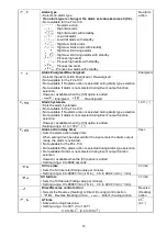
5.7 Output MV (manipulated variable) display
Name, Description
Output MV (manipulated variable) indication
• In the PV/SV display mode, press the
key for approx. 3 seconds.
The display will be changed to Main setting mode during the process, however, keep pressing until
the output MV is indicated.
(MV is indicated on the PV/SV display with the decimal point flashing.)
If the
key is pressed again, the mode will revert to the PV/SV display.
6. Unit operation
After the unit is mounted to the control panel and wiring is completed, operate the unit following
the procedures below.
(1) Turn the power supply to the FCL ON
• For approx. 2 seconds after the power is switched ON, the PV/SV display indicates the sensor input
characters. Refer to (Table 5-1) and (Table 5-2).
During this time, all outputs and LED indicators are in OFF status.
• After that, the PV/SV display indicates PV (process variable).
If SV display is selected during “PV/SV display switching”, the SV will be indicated.
• While the Control output OFF function is working, the PV/SV display indicates "
".
(2) Input each set value
Input each set value, referring to “5. Setup”.
(3) Turn the load circuit power ON.
Control action starts so as to keep the control target at the SV (desired value).
7. Other functions
7.1 Input burnout
[Overscale]
When the thermocouple or RTD is burnt out, or if the input value exceeds the [Input range high limit
value + 50
(100 )] or more, the control output (OUT) is turned off (for DC current output type, OUT
low limit value), and [
] flashes on the PV/SV display.
However, when the input range high limit value is 999.9, if the input value exceeds 999.9, [
]
flashes on the PV/SV display, and the control is performed until [999.9 + 1% of input span].
[Underscale]
For thermocouple input, if the input value drops to -50
(-100 ) or less, the control output (OUT) is
turned off (for DC current output type, OUT low limit value), and [
] flashes on the PV/SV display.
For RTD input, if the input value drops to [Input range low limit value - 1% of input span] or less,
the control output (OUT) is turned off, and
[
] flashes on the PV/SV display.
However, when the Input range low limit value is -199.9, if the input value drops below -199.9,
[
] flashes on the PV/SV display, and the control is performed until [-199.9 - 1% of input span].
Even in SV display mode, the indication of overscale [
] and underscale [
] have priority
over all displays.
7.2 Self-diagnostic function
The CPU is monitored by a watchdog timer, and when an abnormal status is found on the CPU,
the controller is switched to warm-up status.
7.3 Automatic cold junction temperature compensation
(thermocouple input type)
This detects the temperature at the connecting terminal between the thermocouple and the instrument,
and always maintains at the same status as if the reference junction is located at 0
(32 ).