Shinkawa VM-13V1 Instruction Manual Download Page 12


4.


DESCRIPTION OF EACH SECTION
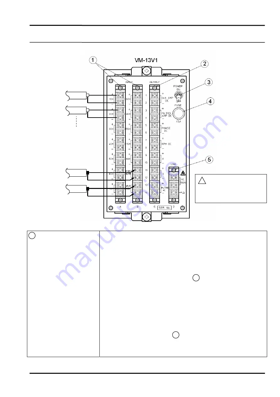
 

VM-13V1


-9-

4-2  REAR PANEL 


 1  Signal Input Terminal Block 

  MEAS. 1ch to 11ch, AUX : 
  Input terminals for up to 11 separate vibration signals and one auxiliary   
 vibration 

signal.  


 Connect vibration signals from vibration transducer or vibration 


  monitor (VM Series) “MONITOR” output.   


 AUX terminals is parallel connection to the front panel AUX   


  Vibration Input Connrctor. (See 4.1 15  on page 8.) 


 Connect signal common to COM treminal indepemdently for each   

    channel. 
  1P/R, NORM, AUX : Input terminal for one (normal) reference signal and   
  one auxiliary refernce signal. 
   

 Connect 1P/R signals from phase marker transducer or Phase Marker   


   (VM-5P) “MONITOR” output.   


 AUX terminlas is parallel connector to the front panel AUX Trigger   


  Input Connector. (See 4.1 13  on page 8.) 


 Connect signal common to COM terminal independently for each   

    channel. 

VIBRATION SIGNAL INPUTS 

1CH 

2CH 

NORMA

(AUX) 

11CH 
(AUX)

 ! 

WARNING 


Beware of electric shock 


from high-voltage parts.

REFERENCE SIGNAL INPUTS 

Summary of Contents for VM-13V1

Page 1: ...MANUAL NO 29361E1 6 Published in Nov 1993 Revised in Aug 2012 MODEL VM 13V1 Vector Monitor INSTRUCTION MANUAL ...

Page 2: ... support the pulled internal board to prevent falling off Since electro sensitive parts are on the internal board care should be taken when handling and adjusting Do not adjust internal switches and or potentiometers unless required This unit is designed for use by specialists or persons thoroughly familiar with the field Make sure that the end user receives the Instruction Manual delivered with t...

Page 3: ...NAL BOARD 11 5 FAULT DISPLAY 5 1 FAULT DISPLAY STATE 18 6 CALIBRATION 6 1 VELOCITY TRANSDUCER SENSITIVITY CALIBRATION 19 6 2 DISPLAY AND OUTPUT CALIBRATION 20 6 3 CALIBRATION POINT LOCATION INTERNAL BOARD LEFT SIDE 21 6 4 CALIBRATION POINT LOCATION INTERNAL BOARD RIGHT SIDE 22 7 MAINTENANCE 7 1 REPLACEMENT OF ALUMINUM ELECTROLYTIC CAPACITOR 23 8 TROUBLESHOOTING 24 9 INPUT SIDE WIRING DIAGRAM 25 ...

Page 4: ...anel LED displays The recorder signal outputs of each data are available on front panel panel BNCs and rear panel terminals A0 A φ VIBRATION SIGNAL BAND PASS OUTPUT 90 0 180 270 A φ GAIN RPM B P F TRACKING FIG 1 1 ROTOR PHASE REF APPLICATION EXAMPLE FOR LARGE TURBINE GENERATOR 3500 35 SPEED DETECTOR PULSE REVOLUTION VIBRATION MONITOR VM SERIES VIBRATION DETECTOR BODE PLOT NYQUIST DIAGRAM FREQUENCY...

Page 5: ...itude VM 13V1 VECTOR MOONITOR rpm Phase Angle X REAL Y IMAG Filtered AC 1 2 11 AUX 1 P R AUX Vibration Signal Input Phase Reference Signal Input DC Recorder Output FIG 1 4 FIG 1 3 BAND WIDTH CONT PLL MULTI SYNC REF GEN N SETL PHASE DETECT XTAL OSC D A 88888 RPM REVOLUTION RPM_DC D A 888 PHAASE DEG PHASE_DC UNIT SEL A D 888 AMPLITUDE mils m m mils m m DUAL RESOLVER DUAL RESOLVER X 1N 2N Y X ADDER D...

Page 6: ...BW 4 FILTER RESPONSE 0 2Hz BW 0 6rpm s 2Hz BW 60rpm s 5 ORDER RATIO 1 1N or 2 2N selected by front panel switch 7 DYNAMIC RANGE 60dB or more 4 INPUT SIGNAL 1 VIBRATION SIGNAL INPUT From displacement transducers or velocity transducers selected by internal switch Input Impedance 10kΩ unbalance Input Sensitivity Displacement transducer 2 5V mm 4V mm 5V mm 8V mm selected by internal switch Velocity t...

Page 7: ... at 25 C 4 X REAL 0 to 10VDC Accuracy 3 of F S at 25 C 5 Y IMAGINARY 0 to 10VDC Accuracy 3 of F S at 25 C 6 X Y POLARITY CW clockwise or CCW counter clockwise selected by internal switch 7 FILTERED AC 10V P P F S 8 EACH OUTPUT IMPEDANCE 100Ω 9 EACH SIGNAL OUTPUT Front panel BNC and rear panel screw terminals 8 TRIGGER PULSE 0 5 to 0 5V PL 4 to 5V PH front panel BNC 6 OTHERS 1 POWER SUPPLY 100VAC 1...

Page 8: ...3 OUTLINE DRAWING VM 13V1 5 ...

Page 9: ...g speed Display range 200 to 99 999rpm 2 AMPLITUDE Display 3 1 2 digit display indicating displacement amplitude in peak to peak selected by the Vibration Input Channal Selector Switch 14 Display range 0 to 500µm or 0 to 19 9mils 3 PHASE Display 3 digit display indicating phase angle selected by the Vibration Input Channal Selector Switch 14 when the VM 13V1 is operated in FILTERED mode Display ra...

Page 10: ...nd width when selecting FILTERD mode by the AMPLMode Selector Switch 5 0 2Hz Band width is 0 2Hz 2Hz Band width is 2Hz AUTO Band width is 0 2Hz below 1 000rpm Band width is 2Hz at 1 000rpm or more Note In 0 2Hz the response of the amplitude and phase output display will become very slow 9 Trigger Mode Selector Switch Used to select the trigger mode AUTO MANUAL for the reference input signal 1P R I...

Page 11: ...Vp p FS 18 Overall Amplitude Signal Output Connector BNC connector to provide overall amplitude signal output 0 to 10VDC FS 19 Filtered Amplitude Signal Output Connector BNC connector to provide filtered amplitude signal output 0 to 10VDC FS 20 X REAL Output Connector BNC connector to provide X real component signal output 0 to 10VDC FS 21 Y IMAG Output Connector BNC connector to provide Y imagina...

Page 12: ...or See 4 1 15 on page 8 Connect signal common to COM treminal indepemdently for each channel 1P R NORM AUX Input terminal for one normal reference signal and one auxiliary refernce signal Connect 1P R signals from phase marker transducer or Phase Marker VM 5P MONITOR output AUX terminlas is parallel connector to the front panel AUX Trigger Input Connector See 4 1 13 on page 8 Connect signal common...

Page 13: ...rovides Y IMAGINARY component signal output 0 to 10VDC FS Provides filtered vibration signal output 0 to 10VDC FS Note Terminal screw ldentification Upper Screw Signal Lower Screw Signal Common Connect signal common to COM terminal independently for each channel 3 Power Supply Switch Lock type 4 Fuse Holder A fuse of 1 5A is inserted Note If the fuse blows check the cause of blowing and take corre...

Page 14: ...ixing tighten four setscrews equally in the same way Note If excessive force is applied the screw thread could be damaged 2 Hold the diagonal two setscrews with fingers and slowly pull out the internal board Note When it is required to completey pull out the internal board support the internal board as shown below Slide lock spring is not attached to this monitor ...

Page 15: ...ernal board obliquely or to the excessive extent may result in twisted flat cable Twisted flat cable cannot be housed properly in the cable case Insertion of the internal chassis without flat cable housed properly in the cable case could cause troubles Cable is twisted ...

Page 16: ...FIX VELOCITY EDDY 10000rpm FS 100000rpm FS POSITIVE NEGATIVE TRIGGER SLOPE SELECTOR SW DC OUTPUT F S SELECTOR SW X Y OUTPUT ROTATION SW CCW Counter clockwise CW Clockwise VIBRATION TRANSDUCER SELECTTION 3 4 1 2 a b c d Installed prior to shipment VEL SENS ADJ POTENTIOMETER 2 5 to 10mV mm sec 10 to 40mV mm sec VARIABLE SEMS MODE FIXED SENS MODE 8mV mm sec VELOCITY TRANSDUCER EDDY CURRENT TRANSDUCER...

Page 17: ...F S ADJ rmp DC 10000rmp FS HYST SET 2 0V 1 5V 1 0V 0 5V UNIT_SELECTOR M M MILS PHASE_DC F S ADJ ZERO ADJ TRIG HYST SET JUMPER AMPLITUDE UNIT SELECTOR SW 6 5 Installed prior to shipment EDDY VEL FIX VAR 10 40 2 5 10VAR_GAIN_ADJ 2 5V mm 4V mm 5V mm 8V mm SENSOR_TYPE SELECT F S_SET_SW EDDY CURRENT TRANSDUCER SENS SELECTOR SW 7 CW CCW ROTATION POLALYTY Installed prior to shipment ...

Page 18: ...ior to shipment 2 PRM DC Output F S Selector SW Used to select RPM DC output full scale 0 2V to 10V 200 to 10 000rpm or 0 02V to 10V 200 to 100 000rpm Note It is set to 0 2V to 10V 200 to 10 000rmp prior to shipment 3 X Y Output Rotation SW Used to select X Y output rotation CW clockwise or CCW counter clockwise CW CCW PHASE ANGLE X Y X Y 0 A 0 A 0 90 0 A 0 A 180 A 0 A 0 270 0 A 0 A A 10V F S PHAS...

Page 19: ...sensitivity mode below FIX 8mV mm sec 0 to peak fixed VAR VEL 2 5 to 40mV mm sec 0 to peak Used to select the sensitivity range when the VAR VEL mode above is selected 2 5 10 2 5 10mV mm sec 0 to peak 10 40 10 40mV mm sec 0 to peak Used to adjust the velocity transducer sensitvity within the range of c 15 turns Note 1 It is set to 8mV mm sec 0 to peak prior to shipment 2 For adjustment procedure s...

Page 20: ...the amplitude unit µm or mils for the Amplitude Dispiay 4 1 2 on page 6 Note It is set to µm unit prior to shipment 7 Eddy Current Transducer Sens Selector SW Used to select the eddy current transducer sensitivity 2 5 4 5 8V mm Note It is set to 8V mm sensitivity prior to shipment ...

Page 21: ... 3sec below 20rpm 4 The RPM Display indicates 00000 and the Phase Display is extinguished The RPM DC Output Phase DC Output and Filtered Amplitude DC Output are disabled Faulty phase reference input 1P R 5 Rotating speed is below minimum measurable rpm 200rpm 5 The RPM Display and Phase Display indicate 00000 The RPM DC Output and Filtered Amplitude DC Output are disabled 1 The vibration signal le...

Page 22: ...ode Selector SW to VAR VEL position Refer to 4 3 5 4 b on page 16 3 Set the Vel Var Sens Range Selector SW to the range that is suitable for the input velocity transducer Refer to 4 3 5 4 c on page 16 4 Calcuate the output voltage of the velocity transducer for 100Hz 500µm amplitude Input the caliculated voltage to the front panel AUX SIGN Input Connrctor Calibration frequency 100Hz 5 Ajust the Ve...

Page 23: ...ibed above The accuracy of the phase angle depends on that of the signal generator Calibration points are shown in 6 3 and 6 4 on page 21 and 22 Do not touch or calibrate other points When calibraing X Y and PHASE ensure the Output Rotation SW and the Trigger Slope SW are set to correct position X Y and PHASE calibration must be performed with use of the two channel oscilloscope in order to check ...

Page 24: ...ELECT rpm DC F S ADJ ZERO ADJ rpm_DC 10000rpm FS 100000rpm FS UNIT_SELECTOR M M MILS PHASE_DC F S ADJ ZERO ADJ SET TO 3 59V DC at 359deg SET TO 0V at 0deg ZERO ADJ POTENTIOMETER F S ADJ POTENTIOMETER PHASE DC OUTPUT F S ADJ POTENTIOMETER ZERO POTENTIOMETER SET TO 0V at 0rpm SET TO 10V DC at F Srpm RPM DC OUTPUT ...

Page 25: ...V at 90deg 1 F S input R164 10V DC at F S input R168 10V DC at F S input R167 10Vp p at F S input ADJUSTEMNT POINT ZERO ADJUSTMENT R174 10V at 180deg 1 F S input R175 10V at 270deg 1 F S input R247 0V at 0V input R254 0V at 0V input R173 0 dig at 0V input CALIBRATION ITEM X REAL DC OUT 10V 10V Y IMAG DC OUT 10V 10V 0 A OVERALL DC OUT 0 10V FS FILTERD DC OUT 0 10V FS FILTERD AC OUT 0 10Vp p FS Amp ...

Page 26: ...ary Replacement by SST is recommended Substrate Name Component No Type Q ty C9 100µF 25WV 1 C36 2200µF 35WV 1 C37 C38 1000µF 50WV 2 C39 C40 470µF 10WV 2 Reference Card C41 C42 220µF 35WV 2 C9 C10 47µF 25WV 2 Counter Phase Card C25 C26 C27 47µF 50WV 3 C109 C110 470µF 25WV 2 Measure Card C111 220µF 35WV 1 To remove or install the monitor proceed according to the instruction manual of the instrument ...

Page 27: ... Faulty manual trigger threshold adjustmant c 2N mode is selected FAULT INDICATION RPM DISPLAY RPM display indicates 0 rpm Trigger LED is off Decimal Points flash The indication randomly changes Decimal points flash Decimal points sometime flash RPM display indicates 2 twice rotating speed CORRECTIVE ACTION a Reduce full scale range a Refer to above b Select FILTERED mode PROBABLE CAUSE a Vibratio...

Page 28: ...tly for each channel VIBRATION SIGNAL INPUT REFERENCE SIGNAL INPUT 1CH NORMAL AUX 11CH AUX 2CH VM 5K DUAL VIBRATION MONITOR VM 5P3 PHASE MAKER UNIT NORMAL VK DRIVER 1CH VK DRIVER AUX VK DRIVER 2CH VK DRIVER 3 11 AUX CH INPUT WIRING DIAGRAM EXAMPLE WITH VM 5 SERIES MONITOR ...

Page 29: ... defects due to improper handling or operation by the user 2 Any defects the case of which is not attributable to Shinkawa Electric 3 Any modifications or repairs made by others than Shinkawa Electric or persons commissioned by Shinkawa Electric 4 Any handling storage and operation under severe environmental conditions that exceed the design specifications 5 Any defects due to fire flood earthquak...

Page 30: ...Hiroshima Factory 4 22 Yoshikawa kogyodanchi Higashi hiroshima 739 0153 Japan Tel 81 82 429 1118 Fax 81 82 429 0804 Field support Repair Dept E Mail service sst shinkawa co jp ...

Reviews: