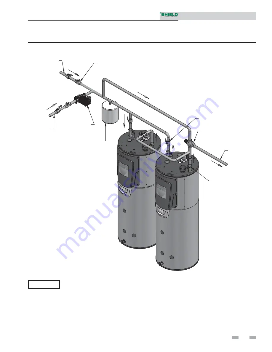
background image

37

5  

System piping 

(continued)


EXPANSION
TANK


BUILDING
RETURN

   SYSTEM
CIRCULATOR

COLD WATER
SUPPLY


FLOW CHECK VALVE
(TYPICAL)


BALL VALVE
(TYPICAL)


   UNION
(TYPICAL)

HOT WATER
SUPPLY


MIXING VALVE
(IF REQUIRED)

IMG00473

Figure 5-3 Multiple Units


Installation & Service Manual

Please note that these illustrations are meant to show system piping concept only, the installer is responsible 
for all equipment and detailing required by local codes.

 NOTICE

Summary of Contents for SNA151-100

Page 1: ... gasoline or other flammable vapors and liquids in the vicinity of this or any other appliance WHAT TO DO IF YOU SMELL GAS Do not try to light any appliance Do not touch any electrical switch do not use any phone in your building Immediately call your gas supplier from a near by phone Follow the gas supplier s instructions If you cannot reach your gas supplier call the fire department Installation...

Page 2: ...witch 43 Louver Relay Output Louver Proving Switch Input 43 Power Cord Connection 43 Runtime Contacts 43 Alarm Contacts 43 8 CONDENSATE DISPOSAL Condensate Drain 46 9 START UP Check for Gas Leaks 47 Inspect fill Condensate System 47 Final Checks Before Starting the Water Heater 47 50 10 OPERATING INFORMATION How the Water Heater Operates 51 Temperature Control 51 Protection Features 51 Water Heate...

Page 3: ... liquids in the vicinity of this or any other appliance WHAT TO DO IF YOU SMELL GAS Do not try to light any appliance Do not touch any electrical switch do not use any phone in your building Immediately call your gas supplier from a near by phone Follow the gas supplier s instructions If you cannot reach your gas supplier call the fire department Installation and service must be performed by a qua...

Page 4: ... cover Allows access to the combustion side of the heat exchanger coils 18 Heat exchanger inlet temperature sensor This sensor monitors the inlet water temperature to the heat exchanger 19 Heat exchanger outlet temperature sensor This sensor monitors heat exchanger outlet water temperature 20 Ignition electrode Provides direct spark for igniting the burner 21 Line voltage junction box The junction...

Page 5: ... 8 22 IMG00461 Left Side inside unit Models 126 065 201 100 18 19 25 3 26 7 33 9 21 17 IMG00461 Right Side inside unit Models 126 065 201 100 The Shield How it works continued 35 2 23 31 27 34 7 13 30 IMG00461 Rear View Models 126 065 201 100 5 Models 126 065 201 100 Installation Service Manual ...

Page 6: ...8 36 27 7 2 35 IMG00461 Rear View Model 501 125 Right Side inside unit Model 501 125 Right Side inside unit Models 286 125 401 125 Models 286 125 401 125 Model 501 125 5 22 26 33 29 32 24 23 1 21 17 9 16 3 13 35 14 20 11 8 IMG00461 IMG00461 5 22 26 33 29 32 24 23 1 21 17 9 16 3 13 35 14 20 11 8 Installation Service Manual ...

Page 7: ...e based on proper combustion calibration and CO2 s adjusted to the recommended levels 4 The Shield 286 125 model can be alternatively vented using a 3 vent air size If the 3 vent air size is used the maximum vent air pipe lengths are limited to 60 equivalent feet each 7 Maximum allowed working pressure is located on the rating plate Model Number Note Change N to L for L P gas models CSA Input Modu...

Page 8: ... you do not provide the minimum clearances shown it may not be possible to service the water heater without removing it from the space Closet and alcove installations This appliance requires a special venting system The vent connection to the appliance must be made with the CPVC pipe section provided with the appliance The field provided vent fittings must be cemented to the CPVC pipe section Use ...

Page 9: ... WARNING 9 1 Determine water heater location continued RECOMMENDED SERVICE CLEARANCES Top 18 457 mm Left Right Side 24 610 mm Front 24 610 mm RECOMMENDED SERVICE CLEARANCES Top 18 457 mm Left Right Side 24 610 mm Front 24 610 mm Installation Service Manual WARNING For closet installations CPVC polypropylene or stainless steel vent material MUST BE used in a closet structure due to elevated tempera...

Page 10: ...om laundry facilities These areas will always contain contaminants WARNING WARNING 1 Determine water heater location Remove water heater from wood pallet 1 Remove the sides and the top of the crate 2 Remove the blocks on the base of the crate to allow for easier removal 3 The water heater can then be slid off the base of the crate for installation Do not drop the water heater or bump the jacket on...

Page 11: ...tion of the common venting system the common venting system should be resized to approach the minimum size as determined using the appropriate tables in Part 11 of the National Fuel Gas Code ANSI Z223 1 NFPA and or CAN CSA B149 1 Natural Gas and Propane Installation Code DANGER WARNING 1 Determine water heater location continued 11 Installation Service Manual Failure to follow all instructions can...

Page 12: ... side with no clearance between adjacent appliances because this appliance is approved for zero clearance from combustible surfaces Consult the Venting section of this manual for specific installation instructions for the appropriate type of venting system that you will be using Figure 1 3_Combustion Air Direct from Outside 1 If air is taken directly from outside the building with no duct provide ...

Page 13: ... cm2 151 100 38 246 cm2 38 246 cm2 75 484 cm2 75 484 cm2 150 968 cm2 150 968 cm2 50 323 cm2 201 100 50 323 cm2 50 323 cm2 100 646 cm2 100 646 cm2 200 1 291 cm2 200 1 291 cm2 67 433 cm2 286 125 72 465 cm2 72 465 cm2 143 923 cm2 143 923 cm2 285 1 839 cm2 285 1 839 cm2 95 613 cm2 401 125 100 646 cm2 100 646 cm2 200 1 291 cm2 200 1 291 cm2 400 2 581 cm2 400 2 581 cm2 134 865 cm2 501 125 125 807 cm2 12...

Page 14: ...bustion air opening a minimum of approximately 25 Check with louver manufacturers for exact net free area of louvers Where two openings are provided one must be within 12 30cm of the ceiling and one must be within 12 30cm of the floor of the equipment room Each opening must have net free area as specified in the chart above Table 1B Single openings shall commence within 12 30cm of the ceiling CAUT...

Page 15: ...vice Manual IMG00464 Figure 2 2 PVC CPVC Concentric Sidewall Termination See page 27 for more details IMG00466 Figure 2 3 Two Pipe Vertical Termination See page 30 for more details IMG00466 Figure 2 4 PVC CPVC Concentric Vertical Termination See page 32 for more details IMG00466 Figure 2 5 Vertical Vent Sidewall Air Direct venting options Vertical Vent ...

Page 16: ...on air piping must be supported per guidelines listed in the National Mechanical Code Section 305 Table 305 4 or as local codes dictate 2 Vent Connector FIG s 2 7 thru 2 10 Used to provide a passageway for conveying combustion gases to the outside A transition fitting is provided on the unit for final connection Vent piping must be supported per the National Building Code Section 305 Table 305 4 o...

Page 17: ...ppliance output rating will reduce by up to 1 5 for each 25 feet of vent length except when using the alternative 3 vent for the Shield 286 125 model which may de rate by up to 4 for each 25 feet of vent length NOTICE Table 2B Concentric Vent Kit Equivalent Vent Lengths Sizing The Shield water heater uses model specific combustion air intake and vent piping sizes as detailed in Table 2A below Tabl...

Page 18: ...Listed silicone sealant such as those manufactured by Dow Corning or General Electric b Do not install seams of vent pipe on the bottom of horizontal runs c Secure all joints with a minimum of three 3 sheet metal screws or pop rivets Apply Aluminum Foil Duct Tape or silicone sealant to all screws or rivets installed in the vent pipe d Ensure that the air inlet pipes are properly supported The PVC ...

Page 19: ...rovisions for combustion and ventilation air must be in accordance with Air for Combustion and Ventilation of the latest edition of the National Fuel Gas Code ANSI Z223 1 in Canada the latest edition of CGA Standard B149 Installation Code for Gas Burning Appliances and Equipment or applicable provisions of the local building codes Commercial applications utilizing the Shield water heater may be in...

Page 20: ...t applied and joint could be defective g Wipe excess cement from the joint removing ring or beads as it will needlessly soften the pipe PVC CPVC Table 2D PVC CPVC Vent Pipe and Fittings All PVC vent pipes must be glued properly supported and the exhaust must be pitched a minimum of a 1 4 inch per foot back to the water heater to allow drainage of condensate NOTICE WARNING The vent connection to th...

Page 21: ...ters and vent system listed in Tables 2E and 2F DO NOT mix vent systems of different types or manufacturers Failure to comply could result in severe personal injury death or substantial property damage WARNING Installations must comply with applicable national state and local codes For Canadian installation polypropylene vent must be listed as a ULC S636 approved system NOTICE Installation of a po...

Page 22: ...stems and terminations listed in Tables 2G and 2H DO NOT mix vent systems of different types or manufacturers Failure to comply could result in severe personal injury death or substantial property damage WARNING Installations must comply with applicable national state and local codes Stainless steel vent systems must be listed as a UL 1738 approved system for the United States and a ULC S636 appro...

Page 23: ...e 3 1A PVC CPVC Polypropylene Sidewall Termination of Air and Vent Follow instructions below when determining vent location to avoid possibility of severe personal injury death or substantial property damage A gas vent extending through an exterior wall shall not terminate adjacent to a wall or below building extensions such as eaves parapets balconies or decks Failure to comply could result in se...

Page 24: ...w or horizontally from any door or window or any other gravity air inlet b Air inlet must terminate at least 12 inches above grade or snow line at least 12 inches below the vent termination and the vent pipe must not extend more than 24 inches vertically outside the building as shown in FIG 3 1B Condensate could freeze and block vent pipe c Do not terminate closer than 4 feet horizontally from any...

Page 25: ...ng through the wall into the vent plate openings Use RTV silicone sealant to seal the air pipe Use the cement primer listed in Table 2D on page 20 to seal the vent pipe 4 Mount and secure the vent plate to the wall using stainless steel screws 5 Seal all gaps between the pipes and wall Seal around the plate to the wall assuring no air gaps 6 Assemble the vent cap to the vent plate see FIG s 3 4A a...

Page 26: ...nch hole for 3 inch vent pipe 5 inch hole for 4 inch vent pipe b Insert a galvanized metal thimble in the vent pipe hole as shown in FIG 3 4C 3 Use a sidewall termination plate as a template for correct location of hole centers 4 Follow all local codes for isolation of vent pipe when passing through floors or walls 5 Seal exterior openings thoroughly with exterior caulk All vent pipes and air inle...

Page 27: ...Figure 3 8 Kit Contents_CVK3007 286 125 501 125 Sidewall termination optional concentric vent Description and usage Lochinvar offers optional concentric combustion air and vent pipe termination kits Factory Kit CVK3003 for 3 diameter Models 126 065 201 100 and CVK3007 for 4 diameter Models 286 125 501 125 Both combustion air and vent pipes must attach to the termination kit The termination kits mu...

Page 28: ...w insulation or other materials to accumulate inside the pipe assembly when installing through the hole 7 Install the rain cap and small diameter pipe assembly into the Y concentric fitting and large pipe assembly Ensure small diameter pipe is bottomed and cemented in the Y concentric fitting for CVK3003 installations and fastened tightly into the rubber adapter for CVK3007 installations 8 Secure ...

Page 29: ...ation of flue gases Figure 3 13 Concentric Vent and Combustion Air Termination Dimension A as Touching or 2 inches Maximum Separation Figure 3 12 Concentric Vent Sidewall Attachment DO NOT use field supplied couplings to extend pipes Airflow restriction will occur and may cause intermittent operation 9 Cement appliance combustion air and vent pipes to the concentric vent termination assembly See F...

Page 30: ...enting Section on page 17 of this manual 2 Prepare the vent termination and the air termination elbow FIG 4 1A by inserting bird screens Bird screens should be obtained locally 3 The vent must terminate at least 3 feet above the highest place in which the vent penetrates the roof and at least 2 feet above any part of a building within 10 horizontal feet 4 The air piping must terminate in a down tu...

Page 31: ...rovide flashing and sealing boots sized for the vent pipe and air pipe Multiple vent air terminations 1 When terminating multiple Shield water heaters terminate each vent air connection as described in this manual FIG 4 2 Terminate all vent pipes at the same height and all air pipes at the same height to avoid possibility of severe personal injury death or substantial property damage WARNING 2 Pla...

Page 32: ...ns a Cement the Y concentric fitting to the larger diameter kit pipe see FIG s 3 7 and 3 8 page 27 b Cement rain cap to the smaller diameter kit pipe see FIG s 3 7 and 3 8 page 27 c Do not attach a U Bent to the rain cap Doing so could cause recirculation see FIG 4 5 NOTICE WARNING 4 Vertical direct venting Installation Service Manual Vertical termination optional concentric vent Description and u...

Page 33: ...tical terminations When two 2 or more direct vent appliances are vented near each other each appliance must be individually vented see FIG 4 7 NEVER common vent or breach vent this appliance When two 2 or more direct vent appliances are vented near each other two 2 vent terminations may be installed as shown in FIG 4 7 It is important that vent terminations be made as shown to avoid recirculation ...

Page 34: ...listed temperature and pressure relief valve will release the manufacturer from any claim which might result from excessive temperature and pressures Keep clear of the combination temperature and pressure relief valve discharge line outlet The discharge may be hot enough to cause scald injury The water is under pressure and may splash Hydrogen gas can be produced in an operating water heater that ...

Page 35: ...rantable premature failure of the heat exchanger Water with a hardness of less than 5 grains per gallon will usually have a pH which can be aggressive and corrosive causing non warrantable damage to the pump and associated piping Corrosion due to water chemistry generally shows up first in the hot water system because heated water increases the rate of corrosive chemical reactions The following ch...

Page 36: ...L BALL VALVE TYPICAL UNION TYPICAL HOT WATER SUPPLY MIXING VALVE IF REQUIRED IMG00471 Figure 5 2 Single Unit Installation Service Manual Please note that these illustrations are meant to show system piping concept only the installer is responsible for all equipment and detailing required by local codes NOTICE ...

Page 37: ...PICAL BALL VALVE TYPICAL UNION TYPICAL HOT WATER SUPPLY MIXING VALVE IF REQUIRED IMG00473 Figure 5 3 Multiple Units Installation Service Manual Please note that these illustrations are meant to show system piping concept only the installer is responsible for all equipment and detailing required by local codes NOTICE ...

Page 38: ...PICAL MIXING VALVE IMG00474 140 HOT WATER SUPPLY 180 HOT WATER SUPPLY THERMOMETER TYPICAL HIGH TEMPERATURE BUILDING RETURN Figure 5 4 Two Temperature Single Unit Installation Service Manual Please note that these illustrations are meant to show system piping concept only the installer is responsible for all equipment and detailing required by local codes NOTICE ...

Page 39: ...25 501 125 5 Purge all air from the gas supply piping 6 Before placing the water heater in operation check the water heater and its gas connection for leaks a The appliance must be disconnected from the gas supply piping system during any pressure testing of that system at a test pressure in excess of 1 2 PSIG 3 5 kPa b The appliance must be isolated from the gas supply piping system by closing a ...

Page 40: ...essure requirements 1 Pressure required at the gas valve inlet pressure port Maximum 14 inches w c with no flow lockup or with water heater on Minimum 4 inches w c with gas flowing verify during water heater startup 2 Install 100 lockup gas pressure regulator in supply line if inlet pressure can exceed 14 inches w c at any time Adjust lockup regulator for 14 inches w c maximum Propane gas Pipe siz...

Page 41: ... top of the gas valve Re tighten the set screw inside the pressure tap Check inlet gas supply NOTICE CSA or UL listed flexible gas connections are acceptable but you must exercise caution to ensure that the line has adequate capacity to allow your water heater to fire at full rate Consult with local codes for proper installation or service procedures DO NOT attempt to measure gas valve outlet pres...

Page 42: ...Figure 6 5 Inlet Gas Supply Check Model 401 125 IMG00479 LOOSEN THE SET SCREW ONE 1 FULL TURN AND PLACE THE MANOMETER TUBING OVER THE PRESSURE TAP DETAIL Figure 6 6 Inlet Gas Supply Check Model 501 125 DO NOT attempt to measure gas valve outlet pressure The gas valve is factory set for the correct outlet pressure This setting is suitable for natural gas and propane when configured for LP requiring...

Page 43: ...e jumper wire from across the ENABLE terminals on the low voltage connection board and connect the wires from the switch in its place Note that the freeze protection feature will still fire the heater even though the enable input is open Louver relay output louver proving switch input When installed using the optional room air configuration the heater is able to control powered louvers used to all...

Page 44: ...44 7 Field wiring Figure 7 3 Low Voltage Field Wiring Connections BUILDING MANAGMENT SYSTEM ALARM BELL LOW WATER CUTOFF IMG00552 Installation Service Manual ...

Page 45: ...MIT SENSOR FLUE GAS SENSOR FLAME SENSOR LOW WATER CUTOFF BLOCKED DRAIN SWITCH DISPLAY PANEL CONTROL BOARD AIR PRESSURE SWITCH LOUVER PROVING SWITCH ENABLE SWITCH IMG00484 LOW VOLTAGE CONNECTION BOARD CONTROL BOARD ALARM BELL RUN TIME CONTACTS WHR PUMP IGNITOR BLOWER GAS VALVE DISPLAY PANEL LOUVER RELAY IMG00484 INPUTS OUTPUTS Installation Service Manual ...

Page 46: ... CPVC pipe fittings and cement 4 A condensate removal pump is required if the water heater is below the drain When installing a condensate pump select one approved for use with condensing water heaters and furnaces The pump should have an overflow switch to prevent property damage from condensate spillage The switch should be wired to the auxiliary device proving switch terminals on the low voltag...

Page 47: ...ater begins to pour out of the drain 4 Replace the cap Press the cap onto the trap until the cap makes contact with the drain 5 Replace the retaining screw WARNING The condensate trap FIG 9 1 must be filled with water during all times of water heater operation to avoid flue gas emission from the condensate drain line Failure to fill the trap could result in severe personal injury or death WARNING ...

Page 48: ...eater at once Find the leak source with a bubble test and repair immediately Do not start the water heater again until corrected Failure to comply could result in severe personal injury death or substantial property damage Check flame and combustion 1 Shut the water heater down by pressing the UP button for five 5 seconds 2 Locate the flue sensor in the vent connection Remove the flue sensor and g...

Page 49: ...49 Figure 9 2 Operating Instructions Models 126 065 286 125 9 Start up continued Installation Service Manual ...

Page 50: ...50 Figure 9 3 Operating Instructions Models 401 125 501 125 9 Start up Installation Service Manual ...

Page 51: ...tors the flue temperature by a sensor located in the flue exhaust If the flue temperature exceeds 215 F the control will reduce the maximum fan speed If the flue temperature exceeds 240 F the control will shut the unit down The unit will restart automatically once the flue temperature drops 25 F and the minimum off time has expired The control monitors the temperature difference between the heat e...

Page 52: ...Press and hold the ENTER and UP keys for 5 seconds to activate Service Mode 7 Press the ENTER and DOWN keys again until P01 appears in the lower digits 8 Press and hold the UP key to readjust the set point to the desired setting 9 Press the ENTER key four 4 times The word SET will appear on the display 10 Press the RESET key to clear the Manual Reset High Limit 11 If Service Mode was activated pre...

Page 53: ...hooting procedures the Service Mode can be accessed by pressing the ENTER and UP buttons simultaneously holding them for five 5 seconds Once in the Service Mode the UP and DOWN buttons control the speed of the blower To toggle between the maximum and minimum speeds press the ENTER button momentarily When ready to return to the normal state press the ENTER button for five 5 seconds The control will...

Page 54: ...er heater when in a lockout Press to select the next menu item Press to store paramater data after paramater programming Press to exit Service Mode Figure 10 1 Control Panel Use the control panel FIG 10 1 to set temperatures operating conditions and monitor water heater operation 10 Operating information Installation Service Manual ...

Page 55: ...ng and connections Perform start up checkout and performance verification per Section 9 in this manual Flame inspection stable uniform Flame signal at least 10 microamps at high fire Clean the heat exchanger if flue temperature is more than 54 F above return water temperature Check anode rods Check Delta T Temperature Rise If combustion or performance indicate need Clean heat exchanger Remove and ...

Page 56: ...iping and verify to be leak free 2 Look for signs of leaking lines and correct any problems found 3 Check gas line using the procedure found in Section 7 Gas Connections Check all piping for leaks The condensate trap must be filled with water during all times of water heater operation to avoid flue gas emission from the condensate drain line Failure to fill the trap could result in severe personal...

Page 57: ...d to avoid water damage Before operating lever check to see that a discharge line is connected to this valve directing the flow of hot water from the valve to a proper place of disposal Otherwise severe personal injury may result If no water flows valve is inoperative Shut down the water heater until a new relief valve has been installed 2 After following the warning directions if the relief valve...

Page 58: ... in this appliance are below the level to convert ceramic fibers to cristobalite Abnormal operating conditions would have to be created to convert the ceramic fibers in this appliance to cristobalite The ceramic fiber material used in this appliance is an irritant when handling or replacing the ceramic materials it is advisable that the installer follow these safety guidelines Avoid breathing dust...

Page 59: ...ny solvent 7 Brush the heat exchanger while dry using a nylon bristle brush Caution DO NOT use a metal brush Re vacuum the heat exchanger 8 Finish cleaning using a clean cloth dampened with warm water Rinse out debris with a low pressure water supply 9 Allow the heat exchanger to thoroughly dry 10 Remove the field supplied rear refractory cover from the back of the combustion chamber of the heat e...

Page 60: ...rify during water heater startup Check control module fuses ALWAYS check control module fuses before replacing control module or any major components blower etc If one of these fuses is blown it can prevent the control module or other components from operating 1 Turn OFF power to the water heater at the external disconnect switch 2 Remove front access cover 3 Remove the control module cover 4 Insp...

Page 61: ...board Blown fuse Replace fuse F3 on the main control board see page 60 of this manual No Burner Operation Tank temperature set point satisfied Review temperature setting Unit locked out on fault Consult display for specific fault Refer to fault descriptions on page 64 of this manual for corrective actions Unit Does Not Modulate Above 50 Flue sensor open Verify that the flue sensor is located in th...

Page 62: ...ance 68 14 773 176 1 707 86 9 804 194 1 266 104 6 652 212 952 122 4 607 230 726 140 3 252 248 560 158 2 337 Checking temperature sensors The water heater temperature sensors inlet water outlet water tank water and flue are all resistance type devices The following tables show the correct values for the sensors at various temperatures Use an ohmmeter to read the resistance of the sensor at a known ...

Page 63: ...ths do not exceed the maximum listed in the General Venting section Dirty damaged burner Refer to page 59 in this manual for the burner removal and inspection procedure Clean or replace the burner as necessary Low water flow through the heat exchanger Very pump operation Air in the piping system Properly purge all air from the piping system No Pump Operation Blown fuse Replace fuse F5 on the contr...

Page 64: ...Blown fuse Replace fuse F2 on the control board see page 60 of this manual E04 will require a manual reset once condition has been corrected Press the RESET button on the display to reset Either the optional flow switch or the optional low water cutoff is not making Check pump operation on a call for heat Check for closed valves or obstructions in the piping Verify system is full of water and all ...

Page 65: ...this manual Replace sensor if necessary E07 Thermal fuse on heat exchanger has opened Check the wiring connections to the fuse on the heat exchanger Check continuity across the thermal fuse If open replace heat exchanger E08 Louver proving switch open Check wiring to louver proving switch Check louver proving switch E09 The blocked drain switch has detected excessive condensate build up inside the...

Page 66: ...ard If 24 vac is present at the main control board check the wiring between the main control board and the gas valve Replace the wiring if necessary Do not disconnect the wiring from the gas valve and attempt to measure voltage at that point The main control board can detect if the gas valve is not connected and will display the Gas Valve or Gas Valve Fail fault If 24 vac is present check the outl...

Page 67: ...er heater Check 120 vac to pump motor on a call for heat If voltage is not present check wiring back to the main control board Replace the main control board if necessary If 120 vac is present on a call for heat and the boiler pump is not operating replace the pump If operating on something other than an outlet sensor check temperature setting of the main control board Check resistance of water se...

Page 68: ...rrected Press the RESET button on the display to reset The inlet sensor is shorted b01 The temperature has reached the set point 4 F None b02 The main control board has received a call for heat too quickly after the previous call for heat has ended The control board will release the call for heat after 60 seconds The control board will release the call for heat if the outlet temperature drops 10 F...

Page 69: ...is installed Check the sensor and its associated wiring Repair or replace the sensor or wiring if damaged n06 Tank sensor is not connected Check the tank sensor and its associated wiring Repair or replace as needed n07 The inlet sensor has been disconnected Check the sensors and their associated wiring Repair or replace the sensor or wiring if damaged Measure the resistance of the sensors and comp...

Page 70: ... actions 7 Once the combustion analysis is complete exit Service Mode Table 12G Troubleshooting Chart Combustion Levels POSSIBLE CAUSE CORRECTIVE ACTION Vent Air Intake Length or Obstruction Refer to Section 2 General Venting for the proper venting and air intake methods for the Shield water heater Check for obstructions at the vent air intake terminals Gas Supply Pressure Refer to Section 7 Gas C...

Page 71: ...G 12 3 Using a screwdriver turn the screw 1 8 turn counterclockwise to increase CO2 levels or 1 8 turn clockwise to decrease CO2 levels After one adjustment on the valve follow the Combustion Analysis Procedure on page 70 of this manual to measure the combustion If combustion is still not within the specified range repeat the procedure This procedure SHOULD NOT be performed more than four 4 times ...

Page 72: ...d or a fault condition is present 2 See wiring diagram for additional notes LOW VOLTAGE 120 VAC HIGH VOLTAGE HIGH VOLTAGE SPARK LEAD CAUTION X5 2 X5 11 X5 10 AIR PRESSURE SWITCH BLOCKED DRAIN SWITCH CN2 7 X4 10 LOUVER RELAY COIL 24VAC LOUVER PROVING SWITCH CN2 8 X4 4 CN2 1 X4 5 LWCO ENABLE SWITCH CN2 10 X4 12 CN2 6 X4 8 CN3 4 CN3 2 CN3 3 CN3 1 24 VAC CONNECTION BOARD 120 VAC 24 VAC 120VAC X1 6 F2 ...

Page 73: ...ring must be installed in accordance with local state provincial and national code requirements per either N E C in USA or C S A in Canada 2 If any original equipment wire as supplied with the appliance must be replaced it must be replaced with wire having same wire gauge AWG and rated for a minimum of 105 C Exceptions Repl acement high voltage spark lead and ribbon cables must be purchased from t...

Page 74: ...74 Notes ...

Page 75: ...75 Notes ...

Page 76: ...ping Chart on page 41 R6621 the addition of the Temperature Parameter Setting Table and HW Temperature Setting instructions on pages 52 and 53 R6658 edits made to the callouts on page 5 R06493 along with updating the flex piping information R06464 on page 21 Revision E ECO C14411 reflects a note that the SNA286 125 model can be vented using 3 diameter pipe up to a maximum of 60 equivalent feet pag...

Reviews: