background image

43

VT-G14
VT-G21

(Bottom side of mechanism chassis)

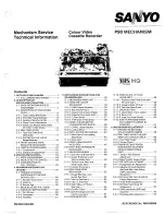
1. Make sure that the loading gear is at the phase-

matching point 

1

 as shown below.

2. Install, paying attention to 

5

 insertion points and 

3

release points.

3. For the phase matching at the insertion point  

1

, see

the phase-matching point 

2

 as shown below.

4. Finally fix the inserts 

1

 and 

4

.

Figure 1-43.

INSTALLING THE SHIFTER

Capstan
D.D. motor

Drum

Reel pulley

Figure 1-42.

Phase-Matching
point 

2

Loading gear(T)

Half round notch

Round mark

Insert
point 

1

Shaft 

1

Sifter

Insert
point 

3

Insert
point 

2

Insert
point 

4

Insert
point 

5

Rotation
point 

2

Release
point 

3

Phase-matching
point 

1

Shaft 

2

Shaft 

1

Shaft 

1

Summary of Contents for VT-G14

Page 1: ...ng Display Control Contrast Colour Brightness Tint Sharpness White temp Symbol and Level Ë Blue Back Off Timer Ë 39 Key Wireless Remote Control Unit Ë Channel Skip Ë High Speed and Double Speed Video Search System PAL MESECAM 3 times 7 times SP LP NTSC 3 times 5 times SP LP 5 times 15 times EP VT G14 VT G21 FEATURE Ë DPSS Digital Program Search System Ë Quick Start Playback with Full Loading Syste...

Page 2: ...DJUSTMENT REPLACEMENT AND ASSEMBLY OF MECHANICAL UNITS 27 ADJUSTMENT OF THE VCR ELECTRICAL CIRCUITRY 46 TROUBLESHOOTING 48 CHASSIS LAYOUT 68 BLOCK DIAGRAM OF TV SECTION 70 DESCRIPTION OF TV SECTION SCHEMATIC DIAGRAM 74 SOLID STATE DEVICE BASE DIAGRAM 75 WAVEFORMS 76 BLOCK DIAGRAM OF VCR SECTION 90 DESCRIPTION OF VCR SECTION SCHEMATIC DIAGRAM 99 PRINTED WIRING BOARD ASSEMBLIES 106 REPLACEMENT PARTS...

Page 3: ... 0 kV at 800 µA Beam Current VT G21 25 0 kV at 1100 µA Beam Current Speaker Output VT G14 3 0 W at Max 5 9 cm oval type 1pc VT G21 3 0 W at Max 5 9 cm oval type 2pcs Picture Tube Type VT G14 VB370BVBK1S S Tint Tube VT G21 VB540ADAC1S S Tint Tube Heater VT G14 6 3 V 300 mA VT G21 6 3 V 600 mA Focus High Bi Potential Electrostatic ËVCR SECTION Outline VHS Video System Colour Video Cassette Recorder ...

Page 4: ...am 0 µA for the set VT G21 When repairing the circuit be sure not to increase the high voltage to more than 29 3 kV at beam 0 µA for the set 2 VT G14 To keep the set in a normal operation be sure to make it function on 22 0 kV 1 5 kV 2 0 kV at beam 800 µA in the case of the set The set has been factory Adjusted to the above mentioned high voltage VT G21 To keep the set in a normal operation be sur...

Page 5: ...Speaker audio turns off when connected to a pair of headphones POWER button VIDEO AUDIO INPUT terminals STOP EJECT button FF Forward Video Search button PLAY button REW Reverse Video Search button PRESET button CHANNEL UP DOWN buttons VOLUME UP DOWN buttons SHARP SUPER PICTURE button This function will create a clearer image during playback REC Recording button REC indicator PROGRAM TIMER indicato...

Page 6: ...ape counter CHILD PROOF LOCK button Used to lock any selected mode FF button Used to fast forward the tape or to conduct Forward Video Search during playback mode STOP button Used to stop the tape PAUSE button Used to temporarily stop the tape during recording mode Used to display a still picture during playback mode DPSS buttons Press the button to search for the index signal and begin playback a...

Page 7: ...ke out the anode cap CRT PWB connectors F G and AO coating ground SP chip fixing screws and others 3 Remove the 2 VT G14 1 VT G21 Main PWB fixing screws and take out the Main PWB unit and the Power PWB 4 Remove the 4 Power PWB fixing screws and take out the Power PWB unit G 3 F AO 2 VT G14 only 4 1 1 VT G21 VT G14 ...

Page 8: ...sette housing control fixing screws and detach the cassette housing control 7 Remove the 4 mechanism chassis fixing screws and detach the mechanism chassis from the Main PWB 8 Remove the 3 Main PWB fixing screws and detach the Main PWB 9 Remove the 4 Tuner Def and IF PWB fixing screws and detach the Tuner Def and IF PWB 5 6 7 7 7 8 9 ...

Page 9: ...side disconnect the lead dressing holder Position the main PWB unit upright as shown below and connect the leads for starting the services 70 80 Note Fit the VCR unit the front cabinet with the front flap door tilted at 70 80 K FRONT F G B B AJ AJ AV AM AN PA PA PB PB SP AN AM AV H AO AO K H ...

Page 10: ...0 31 G CUT OFF 0 255 V OUT PHASE V POS 0 7 B CUT OFF 0 255 H POSITION H POS 0 31 G DRIVE GAIN 0 255 BELL FILTER BELL 0 3 B DRIVE GAIN 0 255 R Y BLACK OFFSET R Y 0 15 B Y BLACK OFFSET B Y 0 15 Y SUB CONTRAST CONT 0 31 SUB COLOUR COLOR 0 240 SUB BRIGHT BRI 0 150 SUB TINT TINT 0 37 NICAM D K N D K 0 1 IF INT EXT IF IN 0 1 AGC GAIN AGCGA 0 31 AGC OFF AGCOF 0 1 FM SOUND ID FMID 0 3 AUTO MUTE AMUTE 0 1 ...

Page 11: ...ing into any other mode or getting out of the service mode Allocation of special buttons in the service mode HORIZONTAL POSITION CONFIRM SET S PICTURE Y MUTE SET COLOUR MAX MIN select TIMER ON OFF DIRECT TUNING MODE RETURN VCR SLOW TEST PROG NVM MODE DISPLAY Adjustment precautions 1 Basically follow the sequential order of adjustments Unless otherwise specified follow the adjustment procedures 2 T...

Page 12: ...K OFFSET 0 15 8 B Y BLACK OFFSET 0 15 8 PICTURE Adjust User setting Initial setting NORMAL CONTRAST at MAX others at CENTER Trouble indicators If the set is interrupted by the protectors the following indicators work to identify a spot in trouble 1 LED red flashing Deflection system protector activated high voltage or beam protector 2 REC LED flashing I2 C bus line error VCJ or tuner EEPROM 3 LED ...

Page 13: ... VCO coil T253 1 Disconnect the antenna from the tuner antenna terminal 2 Apply DC voltage to pin 4 IF AGC TP252 of IC251 DC voltage 6 0 0 1 V 3 Using a digital voltmeter measure the DC volt age at pin 20 PLL FIL TP253 of IC201 The digital voltmeter must be able to take readings down to the third decimal place 10 kHz at 0 007 V 4 Relieve TP252 of the DC voltage 5 Reconnect the antenna in position ...

Page 14: ... R265 slowly in the opposite direction until the voltage goes down 0 1 V below the highest level 5 Adjust the signal level to 63 67 dBµV and make sure there is no noise 6 Now adjust the signal level to 90 95 dBµV and make sure there is no chrominance modulation beat Note If a 50 ohm field strength meter is used without a 50 75 impedance converter set the field strength to 55 1 dBµV Pay atten tion ...

Page 15: ...left landings are equally out ward as shown in Fig B move the deflection yoke forward 3 If the right or left landing is shifted to the right or to the left as shown in Fig C and Fig D adjust the opening angle of the purity magnet 4 Make sure the right and left beam landings are just as specified about the screen center Now check the cathode ray tube corners Be sure that all the landings are at ran...

Page 16: ...ONVERGENCE 1 Adjust the convergence on the fringes of the screen in the following steps Fig a Drive the wedge at point a and swing the deflection coil upward Fig b Drive the wedges at points b and c and swing the deflection coil downward Fig c Drive the c wedge deeper and swing the deflection coil rightward Fig d Drive the d wedge deeper and swing the deflection coil leftward 2 Fix all the wedges ...

Page 17: ...roller call the SUB BRIGHT setting mode BRI Receive the crosshatch and gray scale signal 10 Set the sub brightness data so that the third black portion 1st to 5th counted from the left of the screen of the window pattern looks sinking Note The service mode adjustment in the above steps 9 and 10 should be carried out after the white balance and background adjustments 11 Exit from the service mode 2...

Page 18: ...to get the best linearity V OUT PHASE 50 Hz V CENTER C Select the V OUT POS mode V POS Align the screen center with the cathode ray tube s geo metrical center H POS 50 Hz H CENTER D Select the H POS mode H POS Make the dis tances A and B on both sides equal Exit from the service mode Adjust point Fig 7 2 FOCUS ADJUSTMENT 1 Receive the monoscope pattern signal 2 Make the PICTUREADJUST setting to NO...

Page 19: ...ns up 15 W Y CY G MG R B To be at the same level Fig 8 Ë Ë Ë Ë Ë SECAM CHROMA ADJUSTMENT 1 BELL FILTER ƒ0 I2 C bus data adjustment adjustment not required 1 Receive the SECAM colour bar signal 2 Put the set in the service mode 3 Select the BELL FILTER f0 mode BELL 4 Adjust the data to 1 5 Exit from the service mode W Y CY G MG R B About 3 Vp p Fig 9 Ë Ë Ë Ë Ë NTSC CHROMA ADJUSTMENT 1 SUB TINT ADJU...

Page 20: ...o that the back porch and the white level should become at the same level See Fig 10 6 Select the B Y black offset mode B Y 7 Reconnect the oscilloscope to pin 35 B Y OUT TP801 of IC801 Keep the same conditions as in Step 4 above 8 Vary the data so that the back porch and the white level should become at the same level See Fig 11 9 Quit the service mode 10 Finally adjust the colour control to the ...

Page 21: ... ohm im pedance Make sure the output is as specified 2 6 Vp p 3 dB Be sure that the audio output corresponds to the video output on the screen Ë Ë Ë Ë Ë PROTECTOR PERFORMANCE CHECK 1 BEAM PROTECTOR 1 Receive the monoscope pattern signal 2 Set the contrast control to maximum 3 Set the brightness control to maximum 4 Make a short circuit between the collector and emitter of Q1801 and make sure that ...

Page 22: ...button R C MENU BUTTON PICTURE ADJUST CONTRAST COLOUR BRIGHT TINT SHARPNESS NORMAL 4 TINT 1 Receive the NTSC colour bar signal 2 Using the PICTURE ADJUST control select TINT 3 The tint must be changeable toward green with the button and toward red with the button 5 PIC NORMAL 1 With the PICTURE ADJUST control select NORMAL Make sure the following normal settings are displayed Here are the normal s...

Page 23: ...UTO N3 58 and make sure the col our system does not work properly Note When the NTSC 4 43 colour bar special sig nal is used in the AUTO mode the colour sys tem does not work Check in the forced mode R C MENU BUTTON SYSTEM COLOUR SYSTEM SOUND SYSTEM 9 SOUND SYSTEM 1 Receive the sound system D K signal Using the SOUND SYSTEM button select M B G and I modes and make sure the sound system does not wo...

Page 24: ... and install the mechanism with due care so that the parts are not damaged So as to fix the mechanism to the main PWB tighten up the two screws One for fixing the mechanism and the head amplifier shield the other on the main PWB s soldering side and located near the loading motor Connect again the FFC cable AA MH AD ME AH MZ between the mecha nism and the main PWB PARTS WHICH NEED PARTICULAR CARE ...

Page 25: ...ke ass y 8 Take up main brake ass y 9 Pinch drive cam 10 A C Head ass y 11 Reverse guide lever ass y 12 Casecon drive gear 13 Take up reel disk 14 Pinch roller lever ass y 15 Drum ass y 16 Loading motor 17 Drum motor 18 Take up pole base ass y 27 Fixing guide 28 Impedance roller ass y VT G21 17 15 10 27 11 5 9 14 12 8 16 13 4 6 2 7 3 1 18 28 FUNCTION OF MAJOR MECHANICAL PARTS TOP VIEW ...

Page 26: ... 21 22 19 20 12 23 FUNCTION OF MAJOR MECHANICAL PARTS BOTTOM VIEW No Function No Function 19 Slow brake 20 Master cam 21 Capstan D D motor 22 Reel belt 23 Clutch lever 24 Limiter pulley ass y 12 Casecon drive gear 26 Shifter ...

Page 27: ...up for measuring tape back tension These Jigs are used for checking and adjusting the torque of take up and supply reel disks This Jig is used with the tension gauge Rotary transformer clear ance adjusting jig There are two gauges used for the tension measurements 300 g and 2 0 kg This Jig is used for height adjustment of the reverse guide for reverse guide height ad justment 625 Monoscope and Col...

Page 28: ... forward rewind motion Cassette not loaded or unloaded No tape running tape slack Limiter Pulley Supply Take up Main Brake Levers Tape slack Replace the roller of the cleaner when it wears down Just change the AHC roller assembly for new one Small sound or sound distortion Poor S N ratio no colour Poor flatness of the envelope with alignment tape Clean rubber and rubber contact area with the speci...

Page 29: ...E HOUSING CONTROL ASSEMBLY 1 Short circuit TP7701 J301 and TP7702 J302 2 Plug in the power cord 3 Turn off the power switch The pole bases move into U L position 4 Open the lid of a cassette tape by hand 5 Hold the lid with two pieces of vinyl tape 6 Set the cassette tape in the mechanism chassis 7 Stabilize the cassette tape with a weight 500g to prevent floating 8 Turn on the power switch 9 Perf...

Page 30: ...sion arm ass y Supply reel disk Take up reel disk Supply main brake ass y Take up main brake ass y Tension band ass y Figure 1 4 Note Check that the reel disk is lower than part A but higher than part B If the height is not correct readjust the reel disk height by changing the poly slider washer under the reel disk Reverse guide Position pin Cassette lock release shaft Take up reel disk Figure 1 6...

Page 31: ... ADJUSTMENT OF TAKE UP TORQUE IN REWIND MODE Remove the cassette housing control assembly After short circuiting TP7701 J301 and TP7702 J302 provided at the left on the main PWB plug in the power cord then turn on the power Setting 1 Set a torque gauge to zero on the scale Place it on the supply reel disk 2 Press the rewind button 3 To calculate the remaining capacity slowly rotate the take up ree...

Page 32: ...the REC button and set LP picture record mode 500g Checking 1 Makesurethatvalueiswithinthesetting6 9 2 5mN m 70 25gf cm 2 The winding up torque fluctuates due to variation of rotation torque of limiter pulley ass y Read the center value of fluctuation as setting 3 Set the LP record mode and make sure that the winding up torque is within setting Adjustment 1 If the playback winding up torque is not...

Page 33: ...d at the left on the main PWB plug in the power cord then turn on the power Checking 1 After pressing the play button press the rewind button and set the video search rewind mode 2 Place the torque gauge on the take up reel disk and turn it counterclockwise very slowly one rotation every 2 to 3 seconds and check that the torque is within the set value 3 4 1 5mN m 35 15gf cm Note Set the torque gau...

Page 34: ...n pole adjuster is within 90 range left right CHECKING AND ADJUSTMENT OF RECORD PLAYBACK BACK TENSION Remove the cassette housing control assembly After short circuiting TP7701 J301 and TP7702 J302 provided at the left on the main PWB plug in the power cord Setting 1 Turn off the power switch 2 Open the torque cassette meter and fix with tape 3 Set the cassette tape in loading state 4 Put the weig...

Page 35: ... y or main brake spring Take up reel disk Figure 1 20 A B Adjustment 1 If the indication of torque cassette meter is lower than the setting shift the tension spring engagement to the part A 2 If the indication of torque cassette meter is higher than the setting shift the tension spring engagement to the part B CHECKING THE BRAKE TORQUE Checking the brake torque at the supply side Checking the brak...

Page 36: ...nally tightened Therefore care must be taken 2 After completion of A C head be sure to adjust tape running Execute the running adjustment by the method described in Pages 38 and 39 Replacement 1 Solder the removed PWB to the new head assembly 2 Adjust the height from the A C head plate lower surface to the A C head base to 10 8mm with slide calipers 3 places of azimuth screw section tilt screw sec...

Page 37: ...w until the tape is in the position shown below HEIGHTADJUSTMENTOFREVERSEGUIDE 1 Adjust the height from the mechanism chassis to the reverse guide lower flange to 13 38 mm using the reverse guide height adjustment jig in tape loading state Refer to Figure 1 28 a b 2 Rotate counterclockwise the reverse guide height adjustment nut 1 10 turn For height adjustment use the reverse guide height adjustme...

Page 38: ... adjustment nut Thereby the tape run rough adjustment is facilitated 2 Especially the outlet side envelope waveform must have higher flatness Figure 1 31 Guide roller Cassette Tape 500g Weight of 500g 2 Adjustment of A C head height and azimuth 1 Perform the initial setting of A C head position by the method stated in Page 37 Replacement 3 2 Connect the oscilloscope to the audio output TP6601 3 Us...

Page 39: ...s found remove it as stated in Page 37 HEIGHT ADJUSTMENT OF REVERSE GUIDE item 3 CH 1 CH 2 Figure 1 34 4 A C head X value adjustment 1 Tentatively fix A C head arm screws 1 and 2 by the method described in Page 36 Replacement 3 2 After shortcircuiting TP7701 J301 and TP7702 J302 plug in the power cord turn off the power set the alignment tape VROUBZFS turn on the power and then playback the tape A...

Page 40: ...g point for adjustment of servo circuit Figure 1 38 REPLACEMENT OF THE CAPSTAN D D DIRECT DRIVE MOTOR Remove the mechanism from the main PWB refer to 7 Remove the 4 mechanism chassis fixing screws and detach the mechanism chassis from the Main PWB on page 7 Removal Follow the order of indicated num bers 1 Remove the reel belt 1 2 Remove the three screws 2 Figure 1 37 Reassembly 1 Taking care so th...

Page 41: ... adjustment After that perform also the electrical adjustment Playback switching point adjustment X position adjustment and check 7 After replacing the drum clean the drum Figure 1 39 Figure 1 40 ASSEMBLING OF PHASE MATCHING MECHANISM COMPONENTS Assemble the phase matching mechanism com ponents in the following order 1 Assemble the pinch roller assembly and pinch drive cam 2 Mounting the shifter o...

Page 42: ...Double Action Lever Ass y Pinch Roller Double Action Lever Ass y Phase Matching Point 2 Fit the pinch drive cam so that the notch of pinch drive cam aligns with the dent of pinch drive lever assembly Fit the pinch drive cam so that the notch of pinch drive lever assembly aligns with the half round notch of chassis Turn the reverse guide lever assembly counterclockwise to the stopper 3Insert Open L...

Page 43: ...ng at the insertion point 1 see the phase matching point 2 as shown below 4 Finally fix the inserts 1 and 4 Figure 1 43 INSTALLING THE SHIFTER Capstan D D motor Drum Reel pulley Figure 1 42 Phase Matching point 2 Loading gear T Half round notch Round mark Insert point 1 Shaft 1 Sifter Insert point 3 Insert point 2 Insert point 4 Insert point 5 Rotation point 2 Release point 3 Phase matching point ...

Page 44: ...ace the master cam in the position as shown below E ring XRESJ30 06000 Master cam Fully turn clockwise Fully turn counterclockwise Face the wide tooth side ward Note See the figure below for the phase matching between the master cam and the casecon drive gear 3 Finally fix with the E ring Master cam Casecon drive gear Round mark The loading motor pressing in must be less than 14 7 N 15 gf Adjust t...

Page 45: ...o Gear Drive Gear L and Drive Gear R ASSEMBLY OF CASSETTE HOUSING 1 Drive Gear and R Drive angle ass y MSPRT0381AJFJ Apply grease Apply grease Apply grease LANGF9592AJFW Top surface should be free from scratches or soil Drive angle Drive gear R Frame ...

Page 46: ...c as shown in Figure 2 1 and the adjustment data is memorized in the E2 P ROM IC 5 Then press the STOP button to stop the tape and turn the power off to cancel the SERVICE mode Notes Before the adjustment Electrical adjustments described here are often required after replacement of electronic components and mechanical parts such as video heads Check that the mechanism and all electric components a...

Page 47: ...ote control make adjustment so that jitter becomes minimum 3 Now press the STOP button to stop the tape Adjustment of NTSC System EP still picture vertical sync Measuring Monitor TV instrument Mode Still picture playback Input signal NTSC EP self recording tape Test point Monitor screen Adjusting point CH TR buttons Specification No Vertical jitter 1 Playback the EP Self recorded tape in the NTSC ...

Page 48: ...0 1 0 1 0 1 0 0 0 1 0 1 0 0 0 0 0 0 1 1 1 1 1 VSR PB SLW STP 10 354 12 812 Loading motor turns in reverse direction and master cam counterclockwise CASSETTE INSERTION STOP Cassette inserting Full loading YES YES YES NO NO NO Unloading Loading motor starts in normal direction and master cam counter clockwise Does mechanism position SW come off within 2 5 sec Are start end sensors at low level befor...

Page 49: ...Capstan motor stops NO YES Press STILL button Pinch roller releasing Idler swinging Pinch roller pressing Loading motor turns clockwise and master cam turns counterclockwise Capstan motor in turns reverse direction Loading motor turns counterclockwise Cam switch is at VSR position Set capstan motor to search speed Is supply reel sensor signal outputted Press REW button Release pinch roller Cam swi...

Page 50: ...otor stops End Loading motor turns in clockwise and master cam turns counterclockwise Does 4 supply reel pulses output Does the take up reel pulse output two edges Capstan motor turns clockwise Loading motor turns clockwise Cam switch is at Eject position Loading motor stops Capstan motor stops Press EJECT button Tape unloading Cassette eject End Capstan motor turns clockwise Capstan motor turns c...

Page 51: ...idler wheel ass y and reel disk in mesh Does the pulse output from reel sensor The cassette tape is presumably damaged 2 REC PLAY FAILURE MODE RELEASE NO NO NO NO NO NO NO NO YES YES YES YES YES YES YES YES Is the master cam at PB position Does loading motor operate Modes changing smoothly through cam switch Mode sensor CAM SW A and B system in trouble or master cam malpositioned Loading motor con...

Page 52: ... in mesh Is supply reel disk winding torque normal Does pulse output from reel sensor Check main PWB YES YES YES YES YES NO NO NO NO NO YES YES NO NO YES Press REW button 4 i Unusual sound in cassette insertion and ejection mode Is unusual sound heard during cassette control running Is unusual sound heard with pinch roller lever going up or down Is unusual sound heard during loading unloading Chec...

Page 53: ...ontact with any part on main PWB Turn capstan motor by hand Is unusual sound heard Check drive system s gears for damage Replace damaged gear with new one Reel disk Limiter pulley ass y Idler wheel ass y Check reel disk and main chassis And replace defective parts Adjust reel disk height Rearrange the parts on main PWB Are there thrust gap found at reel disk ...

Page 54: ...l datas clocks between IC1001 and IC7701 Check Q781 and IC780 of PC9V line Is the PC 5V line normal CASSETTE CONTROL TROUBLESHOOTING A cassette tape is not taken in Is the cassette housing distored Does the start sensor cover become open when the cassette tape is inserted Does the start sensor pin 2 of IC7701 go to L level when the cassette tape is inserted Does pin 5 of IC7702 go to H level about...

Page 55: ...O NO Check the take up reel sensor and all the way to IC7701 YES NO Check between pin 6 of IC7702 and all the way up to pin 11 of IC7702 Is reel pluse at pin 80 of IC7701 when the take up reel disk is turning YES NO Is the correct voltage at the loading motor terminal Check between IC7702 and all the way up to the loading motor YES NO Does the loading motor run Replace the cassette cam gear etc Re...

Page 56: ...r AC 1 6 2 7V Insert the cassette and put the unit in FF or REW mode NO Are there the take up supply reel pulses at the collectors of D7702 D7703 Check between D7702 and pin 80 of IC7701 between D7703 and pin 79 of IC7701 Check Replace the take up supply reel sensors D7702 D7703 4 2V 0 4 4V 0 D PG D FG about 4 6V FLOWCHART NO 1 8 HEAD SWITCHING PULSE TROUBLESHOOTING No head switching pulse NO YES ...

Page 57: ...ction between connectors AD and ME or Check replace the drum motor Check between the connector AD and pin 78 of IC7701 and between the connector AD and pin 76 of IC7701 NO YES YES YES NO FLOWCHART NO 1 10 The drum motor runs only for a few seconds Is drum PG signal at pin 3 of AD connector Check between the connector AD and all the way up to pin 86 of IC7701 Is drum PG signal at pin 86 of IC7701 N...

Page 58: ...tput at pin 78 of IC7701 Is there the durm FG signal at pin 87 of IC7701 Check FG and PG signal at pins 3 and 5 of the connector ME and the drum motor Check the signal line of drum PG Is there the drum control voltage applied to pin 7 of connector AD Check the composite sync signal at pin 14 of IC2201 Q2201 Q2202 and Q7706 all the way up to pin 84 of IC7701 Check the signal line between pin 7 of A...

Page 59: ...djust the height of the A C head YES YES Does there appear the capstan FG signal at pin 85 of IC7701 NO YES Check the capstan FG signal line between AC connector and IC7701 Is there capstan control signal at pin 77 of IC7701 YES YES Does there appear the V sync at pin 84 at IC7701 Is there REC CTL signal output at pins 91 92 of IC7701 Is there the capstan control voltage applied to pin 4 of AC con...

Page 60: ... signal line all the way up to pin 57 of IC2201 Check the signal line all the way up to pin 57 of IC2201 NO Check PC5V and the BIAS CTL H line Replace IC3301 NO NO YES YES NO NO FLOWCHART NO 1 14 VCR RECORDING MODE CHROMA TROUBLESHOOTING Record is in black and white E E colour mode Are there Y C data and clock signals at pins 8 and 7 of IC2201 respectively when recording starts Check the PC5V line...

Page 61: ...y when playback starts Check the signal at pin 99 of IC2201 Frequency 4 43MHz PAL SECAM Frequency 3 58MHz NTSC NO Check data and clock signals from pins 52 and 51 of IC7701 Is there a signal at pin 30 of IC3301 X5501 X5502 and peripheral circuit Replace IC2201 NO Check the pin 35 of IC3301 is 0V Bias CTL H line and peripheral circuit of IC3301 YES NORMAL ABNORMAL YES YES Check connector AH Check b...

Page 62: ...84 of IC2201 Check the PC 5V line NO NO Are there the IIC bus date and clock signal at pins 8 and 7 of IC2201 Check between pins 8 and 7 of IC2201 and all the way thru to pins 52 and 51 of IC7701 Is voltage of pins 86 and 88 of IC2201 normal Is there a signal at pin 85 of IC2201 Check signal line between pin 85 of IC2201 and TP6601 Is there L level at pin 72 of IC2201 Check A MUTE H line YES YES R...

Page 63: ...ed remote control function Is 5V applied at pin 2 of the remote control receiver Replace the infrared remote control as required Check pin 79 of IC1001 and or receiver Is fluorescent lighting enough away from the set YES Reposition the set not to be exposed to strong light YES Is there short circuit in the key input or IC1001 Check key input terminals Check IC1001 and signal line of serial datas s...

Page 64: ...t pin 1 of IC401 Check IC401 and adjacent parts NO NO Is there a signal at pin 47 of IC801 Check IC801 and adjacent parts Check IF Circuit and tuner bias Check Tuner AGC R475 C481 NO NO NO NO YES YES YES YES YES YES YES Check the signal line between pin 3 of IC351 and pin 8 of IC301 Is there a signal at pin 3 of IC351 Is there a signal at pin 1 of IC301 NO Check or replace IC351 and or adjacent pa...

Page 65: ...ICTURE Is there a signal at pin 1 of IC801 Check IC801 and adjacent parts as same as NO PICTURE Check the VCR TROUBLE SHOOTING NO PLAYBACK YES Does waveform appear at pin 8 of IC351 Check the speaker Normal Pin 53 of IC801 Abnormal IC801 pin 54 bias check Normal IC801 Abnormal IC501 bias check Normal D501 D504 C503 C504 C511 R513 Abnormal Check the connectors F5 F6 and adjacent parts NO YES FLOWCH...

Page 66: ...R SECAM NO NO NO NO NO YES YES YES YES Is there a chroma signal at pin 42 of IC801 Specific colours are not produced in colour broadcast reception Is some colour produced in B W broadcast reception When change channel does colour appear Colour appears but colour shading NO NO YES When colour control minimum colour disappears Check IF Circuit and adjacent parts Is the white balance properly adjuste...

Page 67: ...te balance properly adjusted Is some colour produced in B W broadcast reception Readjust the white balance The picture colour is green or magenta Check Q1801 and its adjacent circuits Q1802 for VT G14 The picture colour is red or cyan Check Q1802 and its adjacent circuits Q1801 for VT G14 The picture colour is blue or yellow Check Q1803 and its adjacent circuits IC801 X801 16 2MHz Specific colours...

Page 68: ... 1 A B C D E F G H CHASSIS LAYOUT PWB B TUNER DEF UNIT PWB G IF UNIT PWB C POWER UNIT PWB D ONLY for VT G21 CRT UNIT PWB D ONLY for VT G14 CRT UNIT PWB F ONLY for VT G21 KEY UNIT PWB F ONLY for VT G14 KEY UNIT MAIN UNIT PWB A PWB E FRONT AV UNIT ...

Page 69: ...71 VT G14 VT G21 70 12 11 10 9 8 7 6 5 4 3 2 1 A B C D E F G H BLOCK DIAGRAM OF TV SECTION 1 ...

Page 70: ... VT G14 VT G21 72 12 11 10 9 8 7 6 5 4 3 2 1 A B C D E F G H BLOCK DIAGRAM OF TV SECTION 2 PWB D CRT UNIT Only for VT G14 PWB D CRT UNIT Only for VT G21 PWB B TUNER DEF UNIT PWB C POWER UNIT PWB G IF UNIT ...

Page 71: ...CT AN ISOLATING TRANSFORMER BETWEEN TV RECEIVER AC LINE TO ELIMINATE HAZARD OF ELECTRIC SHOCK CAUTION This circuit diagram is original one therefore there may be a slight difference from yours NOTES 1 The unit of resistance Ω is omitted K kΩ 1000 Ω M MΩ 2 All resistors are 1 8 watt unless otherwise noted 3 The unit of capacitance F is omitted µ µF P µµF 4 The values in parentheses are the ones in ...

Page 72: ...CTOR EMITTER 2SC2229 2SC2482 2SC3939 BASE COLLECTOR EMITTER KTA1024 DTC144ES BASE COLLECTOR EMITTER B C E 2SD1877 2SD2586 1 2 3 STRF6654 1 2 3 4 5 1 2 3 SE115N PST600D KiA7045P TDA7056A PQ09RD11 2SD1944 1 2 3 1 9 TA7348P 1 9 BA7755 1 5 1 4 iX3057CE NN3572F 1 30 80 51 31 50 100 81 iX3109CE 1 24 64 41 80 65 25 40 BA6209 1 10 2SC3851 B C E 2SC3789 E C B E C B 2SB564 2SD471 2SB1117 E C B 1 7 LA7830 iX...

Page 73: ...C 1 7V 2 AC 0 9Vp p DC 1 8V 3 AC 2 7Vp p DC 1 2V 4 AC 2 8Vp p DC 1 2V 5 AC 3 0Vp p DC 1 2V 6 AC 1 8Vp p DC 0V 7 AC 1 5Vp p DC 0V 8 AC 47Vp p DC 2V 9 AC 140Vp p DC 0V 0 AC 950Vp p DC 0V q AC 1 0Vp p DC 0V w AC 110Vp p DC 138V e AC 110Vp p DC 135V r AC 110Vp p DC 140V t ...

Page 74: ...C 1 7V 2 AC 0 9Vp p DC 1 8V 3 AC 2 7Vp p DC 1 2V 4 AC 2 8Vp p DC 1 2V 5 AC 3 0Vp p DC 1 2V 6 AC 1 8Vp p DC 0V 7 AC 1 5Vp p DC 0V 8 AC 47Vp p DC 2V 9 AC 122Vp p DC 0V 0 AC 1030Vp p DC 0V q AC 1 0Vp p DC 0V w AC 104Vp p DC 124V e AC 116Vp p DC 124V r AC 124Vp p DC 128V t ...

Page 75: ...79 VT G14 VT G21 78 12 11 10 9 8 7 6 5 4 3 2 1 A B C D E F G H MODEL VT G14 SCHEMATIC DIAGRAM OF TV SECTION MAIN and FRONT AV Unit ...

Page 76: ...80 VT G14 VT G21 6 5 4 3 2 1 A B C D E F G H MODEL VT G14 SCHEMATIC DIAGRAM OF TV SECTION CRT and POWER Unit ...

Page 77: ...81 VT G14 VT G21 6 5 4 3 2 1 A B C D E F G H MODEL VT G14 SCHEMATIC DIAGRAM OF TV SECTION KEY and IF Unit ...

Page 78: ...83 VT G14 VT G21 82 12 11 10 9 8 7 6 5 4 3 2 1 A B C D E F G H MODEL VT G14 SCHEMATIC DIAGRAM OF TV SECTION TUNER DEF Unit ...

Page 79: ...85 VT G14 VT G21 84 12 11 10 9 8 7 6 5 4 3 2 1 A B C D E F G H MODEL VT G21 SCHEMATIC DIAGRAM OF TV SECTION MAIN and FRONT AV Unit ...

Page 80: ...86 VT G14 VT G21 6 5 4 3 2 1 A B C D E F G H MODEL VT G21 SCHEMATIC DIAGRAM OF TV SECTION CRT and POWER Unit ...

Page 81: ...87 VT G14 VT G21 6 5 4 3 2 1 A B C D E F G H MODEL VT G21 SCHEMATIC DIAGRAM OF TV SECTION KEY and IF Unit ...

Page 82: ...89 VT G14 VT G21 88 12 11 10 9 8 7 6 5 4 3 2 1 A B C D E F G H MODEL VT G21 SCHEMATIC DIAGRAM OF TV SECTION TUNER DEF Unit ...

Page 83: ...91 VT G14 VT G21 90 12 11 10 9 8 7 6 5 4 3 2 1 A B C D E F G H BLOCK DIAGRAM OF VCR SECTION Ë OVERALL BLOCK DIAGRAM ...

Page 84: ...93 VT G14 VT G21 92 12 11 10 9 8 7 6 5 4 3 2 1 A B C D E F G H BLOCK DIAGRAM OF VCR SECTION Ë SERVO PROCESS BLOCK DIAGRAM ...

Page 85: ...94 VT G14 VT G21 6 5 4 3 2 1 A B C D E F G H BLOCK DIAGRAM OF VCR SECTION Ë SYSTEM CONTROL BLOCK DIAGRAM ...

Page 86: ...95 VT G14 VT G21 6 5 4 3 2 1 A B C D E F G H BLOCK DIAGRAM OF VCR SECTION Ë SAFETY DEVICE BLOCK DIAGRAM ...

Page 87: ...97 VT G14 VT G21 96 12 11 10 9 8 7 6 5 4 3 2 1 A B C D E F G H BLOCK DIAGRAM OF VCR SECTION Ë AUDIO BLOCK DIAGRAM ...

Page 88: ...98 VT G14 VT G21 6 5 4 3 2 1 A B C D E F G H BLOCK DIAGRAM OF VCR SECTION Ë Y C BLOCK DIAGRAM ...

Page 89: ...00 Ω M MΩ 2 All resistors are 1 16 watt unless otherwise noted 3 The unit of capacitance F is omitted µ µF P µµF 4 The values in parentheses are the ones in the PB mode the values without parentheses are the ones in the REC mode VOLTAGE MEASUREMENT CONDITIONS 1 DC voltages are measured between points indicated and chassis ground by VTVM with AC 220 240V 50 60Hz supplied to unit and all controls ar...

Page 90: ...101 VT G14 VT G21 100 12 11 10 9 8 7 6 5 4 3 2 1 A B C D E F G H SCHEMATIC DIAGRAM OF VCR SECTION VCR 1 Unit ...

Page 91: ...103 VT G14 VT G21 102 12 11 10 9 8 7 6 5 4 3 2 1 A B C D E F G H MODEL VT G14 SCHEMATIC DIAGRAM OF VCR SECTION VCR 2 Unit ...

Page 92: ...105 VT G14 VT G21 104 12 11 10 9 8 7 6 5 4 3 2 1 A B C D E F G H MODEL VT G21 SCHEMATIC DIAGRAM OF VCR SECTION VCR 2 Unit ...

Page 93: ...106 VT G14 VT G21 6 5 4 3 2 1 A B C D E F G H PRINTED WIRING BOARD ASSEMBLIES PWB C POWER Unit Wiring Side ...

Page 94: ...107 VT G14 VT G21 6 5 4 3 2 1 A B C D E F G H PWB F KEY Unit Wiring Side PWB D CRT Unit Wiring Side ...

Page 95: ...109 VT G14 VT G21 108 12 11 10 9 8 7 6 5 4 3 2 1 A B C D E F G H PWB A MAIN Unit Wiring Side ...

Page 96: ...111 VT G14 VT G21 110 12 11 10 9 8 7 6 5 4 3 2 1 A B C D E F G H PWB A MAIN Unit Chip Parts Side ...

Page 97: ...112 VT G14 VT G21 6 5 4 3 2 1 A B C D E F G H PWB G IF Unit PWB E FRONT AV Unit Wiring Side Wiring Side Chip Parts Side ...

Page 98: ...113 VT G14 VT G21 6 5 4 3 2 1 A B C D E F G H Chip Parts Side Wiring Side PWB B TUNER DEF Unit ...

Page 99: ...SB564 AC Q1003 VSUN2213 1 R UN2213 AA Q1004 VS2SC2412KQ 1 R 2SC2412K AA Q1005 VS2SC2412KQ 1 R 2SC2412K AA Q1006 VS2SC2412KQ 1 R 2SC2412K AA Q1007 VSUN2213 1 R UN2213 AA Q2206 VS2SA1037KQ 1 R 2SA1037K AA Q2207 VS2SA1037KQ 1 R 2SA1037K AA Q2208 VS2SC2412KQ 1 R 2SC2412K AA Q2209 VS2SC2412KQ 1 R 2SC2412K AA Q2210 VS2SC2412KQ 1 R 2SC2412K AA Q2215 VS2SC2412KQ 1 R 2SC2412K AA Q2217 VS2SC2412KQ 1 R 2SC24...

Page 100: ...210 VP XF221K0000 R Peaking 220µH AB L2214 VP ZK221K0000 R Peaking 220µH AB L2223 RCiLP0312CEZZ R Coil AE L3301 VP MK101K0000 R Peaking 100µH AB L6601 VPADK153J0000 R Peaking 15mH AC L6604 VP DF221K0000 R Peaking 220µH AB L6605 VPADK822J0000 R Peaking 8 2mH AC L6607 VP DF180K0000 R Peaking 18µH VT G14 AB L6607 VP DF8R2K0000 R Peaking 8 2µH VT G21 AB L6610 VPADK153J0000 R Peaking 15mH AC L7701 VP X...

Page 101: ...V Electrolytic AB C2215 VCCCCY1HH201J R 200p 50V Ceramic AD C2216 VCKYCY1CF474Z R 0 47 16V Ceramic AB C2217 VCEA9A1HW474M R 0 47 50V Electrolytic AB C2218 VCKYCY1HF103Z R 0 01 50V Ceramic AA C2219 VCCCCY1HH330J R 33p 50V Ceramic AA C2220 VCKYCY1HF103Z R 0 01 50V Ceramic AA C2221 VCKYCY1CF104Z R 0 1 16V Ceramic AA C2222 VCEA9A1CW106M R 10 16V Electrolytic AB C2223 VCEA9A1HW105M R 1 50V Electrolytic...

Page 102: ...1 16W Metal Oxide AA RJ18 VRS CY1JF000J R 0 1 16W Metal Oxide AA RJ21 VRS CY1JF000J R 0 1 16W Metal Oxide AA RJ23 VRS CY1JF000J R 0 1 16W Metal Oxide AA RJ25 VRS CY1JF000J R 0 1 16W Metal Oxide AA RJ26 VRS CY1JF000J R 0 1 16W Metal Oxide AA RJ27 VRS CY1JF000J R 0 1 16W Metal Oxide AA RJ28 VRS CY1JF000J R 0 1 16W Metal Oxide AA RJ30 VRS CY1JF000J R 0 1 16W Metal Oxide AA RJ31 VRS CY1JF000J R 0 1 16...

Page 103: ...J R 5 6k 1 16W Metal Oxide AA R1068 VRS CY1JF103J R 10k 1 16W Metal Oxide AA R1069 VRS CY1JF333J R 33k 1 16W Metal Oxide AA R1070 VRS CY1JF103J R 10k 1 16W Metal Oxide AA R1071 VRS CY1JF562J R 5 6k 1 16W Metal Oxide AA R1072 VRS CY1JF221J R 220 1 16W Metal Oxide AA R1073 VRS CY1JF221J R 220 1 16W Metal Oxide AA R1074 VRD RM2HD101J R 100 1 2W Carbon AA R1086 VRS CY1JF221J R 220 1 16W Metal Oxide AA...

Page 104: ...393J R 39k 1 16W Metal Oxide AA R7755 VRS CY1JF183J R 18k 1 16W Metal Oxide AA R7756 VRS CY1JF102J R 1k 1 16W Metal Oxide AA R7757 VRS CY1JF223J R 22k 1 16W Metal Oxide AA R7758 VRS CY1JF153J R 15k 1 16W Metal Oxide AA R7759 VRS CY1JF102J R 1k 1 16W Metal Oxide AA R7760 VRS CY1JF102J R 1k 1 16W Metal Oxide AA R7761 VRS CY1JF274J R 270k 1 16W Metal Oxide AA R7762 VRS CY1JF224J R 220k 1 16W Metal Ox...

Page 105: ...r for LED AD LHLDW1019PEZZ J Holder AB LHLDZ1962AJ00 J Holder for Start End Sensor AD PSLDM0251PEFW J Shield for H A Top AD PSLDM0252PEFW J Shield for H A Bottom AD PWB A DUNTK9568WEV0 V1 MAIN UNIT Continued TUNER NOTE THE PARTS HERE SHOWN ARE SUPPLIED AS AN ASSEMBLY BUT NOT INDEPENDENTLY å TU201 VTUVTST6HD64 R Tuner BF INTEGRATED CIRCUITS IC201 RH iX0037CEZZ R UPC574J AF IC301 VHiTA7348P 1 J Audi...

Page 106: ... AB R301 VRS CY1JF101J R 100 1 16W Metal Oxide AA R303 VRS CY1JF821J R 820 1 16W Metal Oxide AA R304 VRS CY1JF104J R 100k 1 16W Metal Oxide AA PWB B DUNTK9570WEV0 V1 TUNER DEF UNIT Continued R305 VRS CY1JF472J R 4 7k 1 16W Metal Oxide AA R316 VRS CY1JF153J R 15k 1 16W Metal Oxide AA R317 VRS CY1JF101J R 100 1 16W Metal Oxide AA R318 VRS CY1JF101J R 100 1 16W Metal Oxide AA R401 VRS CY1JF101J R 100...

Page 107: ...AX å IC751 VHiSE115N 1 R Error Detector AF TRANSISTORS Q701 VS2SC2229O 1E R 2SC2229 O AD Q702 VSDTC144ES 1 R DTC144ES AB Q703 VSDTC144ES 1 R DTC144ES AB Q751 VSDTC144ES 1 R DTC144ES AB Q752 VS2SA1266 Y 1 R 2SA1266 Y AA Q753 VS2SC3198 G 1 R 2SC3198 G AA Q754 VS2SA1266 Y 1 R 2SA1266 Y AA Q755 VSDTC144ES 1 R DTC144ES AB Q757 VSKTA1024 Y 1 R KTA1024 Y AD Q758 VS2SC2229O 1E R 2SC2229 O AD Q761 VS2SD194...

Page 108: ... UA2HG825K R 8 2M 1 2W Solid AA å R741 VRC UA2HG825K R 8 2M 1 2W Solid AA R743 VRD RA2BE473J R 47k 1 8W Carbon AA R744 VRD RA2BE473J R 47k 1 8W Carbon AA R745 VRD RA2BE104J R 100k 1 8W Carbon AA R746 VRD RA2BE473J R 47k 1 8W Carbon AA R747 VRD RM2HD273J R 27k 1 2W Carbon AA R748 VRD RA2BE472J R 4 7k 1 8W Carbon AA R751 VRD RM2HD122J R 1 2k 1 2W Carbon AA R753 VRD RA2BE472J R 4 7k 1 8W Carbon AA R7...

Page 109: ...72J R 2 7k 1 2W Carbon AA R1820 VRD RM2HD272J R 2 7k 1 2W Carbon AA R1821 VRD RM2HD272J R 2 7k 1 2W Carbon AA R1822 VRD RA2BE100J R 10 1 8W Carbon AA MISCELLANEOUS PARTS CN1801 QCNW 2243PEZZ J Connecting Cord VT G14 AF CN1801 QCNW 2244PEZZ J Connecting Cord VT G21 AG CN1802 QCNW 2241PEZZ J Connecting Cord VT G14 AF CN1802 QCNW 2242PEZZ J Connecting Cord VT G21 AF FB1801 RBLN 0037CEZZ R Ferrite Bea...

Page 110: ...R 0 68 50V Mylar AD C277 VCCCCY1HH470J R 47p 50V Ceramic AA C278 VCCCCY1HH270J R 27p 50V Ceramic AA RESISTORS R252 VRS CY1JF151J R 150 1 16W Metal Oxide AA R253 VRS CY1JF680J R 68 1 16W Metal Oxide AA R254 VRS CY1JF562J R 5 6k 1 16W Metal Oxide AA R255 VRS CY1JF272J R 2 7k 1 16W Metal Oxide AA PWB G DUNTK9573FMV0 V1 IF UNIT R256 VRS CY1JF561J R 560 1 16W Metal Oxide AA R257 VRS CY1JF000J R 0 1 16W...

Page 111: ...RTS 22 31 12 20 18 214 19 29 49 51 8 11 203 49 51 7 7 58 52 4 25 24 2 33 15 1 50 218 207 67 207 63 62 66 66 66 53 65 216 41 61 21 38 17 208 60 47 44 6 30 36 9 39 45 219 10 30 40 224 27 43 46 43 35 35 37 34 23 62 48 209 210 211 212 213 223 5 26 32 68 69 55 16 202 222 221 201 202 202 220 59 70 57 71 56 73 216 VT G21 VT G14 VT G21 72 ...

Page 112: ...0287AJZZ V Auto Head Cleaner Ass y AG 27 MSLiP0010AJZZ V Shifter AH 29 MSPRD0175AJFJ V Reverse Guide Spring 2 AE 30 MSPRT0402AJFJ V Loading Double Action AE Spring 31 MSPRT0403AJFJ V Pinch Double Action AD Spring 32 MSPRC0213AJFJ V Earth Spring AC 33 MSPRT0416AJFJ V Tension Spring AD 34 NBLTK0067AJ00 V Drive Belt AE 35 NDAiV1078AJ00 V Reel Disk AE 36 NGERH1293AJZZ V Loading Connect Gear AD 37 NGER...

Page 113: ...Part No Description Code Ref No Part No Description Code 128 VT G14 VT G21 6 5 4 3 2 1 A B C D E F G H CASSETTE HOUSING CONTROL PARTS 301 300 304 311 308 311 305 306 309 303 312 316 315 307 314 310 317 313 302 ...

Page 114: ...GEFD J Tilt Adjusting Screw AA 221 XBPSD26P06000 V Azimuth Adjusting Screw AA 2 6 6S 222 LX BZ3197GEFD J Screw A C Head AD 223 XWHJZ31 08052 V Washer W3 1 5 2 0 8 AC 224 LX RZ3015GEFJ V CS Washer 3 AB SCREW NUTS AND WASHERS CASSETTE HOUSING CONTROL PARTS 300 CHLDX3081TEV2 V Cassette Housing Control AX Ass y 301 LANGF9592AJFW V Upper Plate AL 302 LHLDX1028AJ00 V Frame L AH 303 LHLDX1032AJ00 V Frame...

Page 115: ...38 39 24 43 PWB C 18 PWB D PWB A 18 25 18 25 27 25 17 25 26 23 15 25 26 24 24 36 35 41 41 1 10 1 19 1 19 1 18 1 19 1 16 1 7 1 1 7 2 1 15 1 6 1 10 1 1 1 14 33 10 7 18 22 20 22 28 18 40 6 31 20 16 22 32 16 22 1 4 1 11 26 4 24 1 8 1 3 8 11 28 21 19 47 46 26 48 PWB F PWB E 13 49 34 PWB B 3 3 3 37 29 1 2 1 20 1 17 1 17 A A 17 2 2 2 ...

Page 116: ...0038PEFW R Angle AC 10 QEARC1414PEZZ R Wire Grounding Strap AK 11 LCHSM0074PEZZ R Main Chassis Frame AU 13 LHLDK0002PEK0 R AC Cord Holder AA 15 PSLDM0253PEFW R Shield Angle AC 16 LHLDW0003PEKZ R Degaussing Coil Holder x4 AC 17 LHLDW1047PEZZ R Wire Holder x4 AB 18 LHLDW1019PEZZ R Wire Holder x6 AB 19 LHLDW1074PEKZ R Wire Holder AD 20 PSPAG0004PEZZ R Wedge Gum x3 AB 21 TLABM1402PEZZ R Model Label AC...

Page 117: ... 16 22 20 31 22 22 20 21 Z 1 7 2 1 7 1 30 42 42 42 42 PWB E 1 2 1 12 44 25 9 24 38 39 24 PWB C PWB D PWB A 18 25 18 25 17 25 26 23 15 25 26 7 18 18 18 40 6 26 24 8 11 28 19 18 25 24 26 27 47 36 35 41 10 33 PWB B 1 1 1 14 1 10 1 13 1 16 1 15 1 5 1 5 46 2 PWB F 34 Z A 13 3 3 3 29 37 A MODEL VT G21 CABINET AND MECHANICAL PARTS ...

Page 118: ...PSPAG0003PEZZ R Wedge Gum x3 AD 21 TLABM1407PEZZ R Model Label AC 22 LX TZ0017PEFD R Screw for CRT x4 AF 23 LHLDW1074PEKZ R Wire Holder x1 AD 24 LX HZ3001PEFD R Screw x6 AA 25 XEBSD30P12000 R Screw x22 AA 26 XHPSD30P06WS0 R Screw x5 AA 27 XTASD40P20000 R Screw x9 AA 28 XTASD40P20000 R Screw x1 AA 29 LCHSM0075PEZZ R Power Chassis Frame AP å 30 VB540ADAC1S S R Picture Tube V801 CG å 31 RCiLH0146PEZZ...

Page 119: ... D K or I BLUE BACKGROUND ON VIDEO ADJUST RESET POWER LAST POWER ON MAIN SWITCH OFF TAPE SPEED SP WOUND UP OFF SLEEP TIMER OFF CLOCK OFF REAR Packing Case Serial Number Label MARK Not replacement items Number Card FRONT Buffer Material Polystyrene Sack Polystyrene Bag Use 22 staples to fix the packing case Operation Manual Batteries Infrared R C unit ...

Page 120: ... D K or I BLUE BACKGROUND ON VIDEO ADJUST RESET POWER LAST POWER ON MAIN SWITCH OFF TAPE SPEED SP WOUND UP OFF SLEEP TIMER OFF CLOCK OFF REAR Use 22 staples to fix the packing case Packing Case Serial Number Label MARK Not replacement items Number Card FRONT Buffer Material Polystyrene Sack Polystyrene Bag Operation Manual Batteries Infrared R C unit ...

Page 121: ... in a retrieval system or transmitted in any form or by any means electronic mechanical photocopying recording or otherwise without prior written permission of the publisher D JAPAN P SREC TQ1053 S Jan 2001 Printed in Japan NA KG SHARP CORPORATION AV Systems Group Quality Reliability Control Center Yaita Tochigi 329 2193 Japan ...

Reviews: