10
VL-Z1U
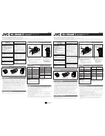
4-2. Procedure for disassembling the cabinet
1.
· Remove the three screws ((e) XiPSF17P03000) , remove the screw
((d) XiPSF17P02000) and remove the VCR bottom cover.
2.
· Remove the two screws ((e) XiPSF17P03000) and remove the tilt
cover.
· Remove the VCR front cover with the cassette cover opened.
· Disconnect the connector and two tilt FPCs, remove the three screws
((h) LX-BZ0220TAFC) and remove the KS camera tilt.
3.
· Remove the screw ((f) XiPSF17P04000) with the cassette lid opened,
disconnect the operation PWB FFC and remove the KS VCR operating
cover.
e
VCR bottom cover
e
e
d
h
h
h
Tilt cover
VCR front cover
Connector
Tilt FPC
e
e
KS camera unit
f
KS VCR operating cover
Operating PWB FFC
The internal lug
may be damaged
If the VCR front cover is removed
only by turning it in the direction
indicated
1. Remove the two couplings and turn the VCR front cover about 20 degrees in
the direction indicated by (1).
2. Turn the VCR front while sliding it in the direction indicated by (2) to disengage
the internal lug.
* If the VCR front cover is removed by turning it forcedly in the direction indicated
by (1), the internal lug may be damaged.
How to remove the VCR front cover
1
2
Summary of Contents for Viewcam VL-Z1U
Page 26: ...26 VL Z1U 9 5 4 Diagram of greasing oiling locations ...
Page 57: ...57 VL Z1U M E M O ...
Page 58: ...59 58 VL Z1U VL Z1U 14 SCHEMATIC DIAGRAMS 14 1 OVERALL SCHEMATIC DIAGRAM ...
Page 90: ...121 A B C D E F G H I J 1 2 3 4 5 6 7 8 9 10 VL Z1U 14 33 HOLE SENSOR UNIT SCHEMATIC DIAGRAM ...
Page 107: ...140 VL Z1U M E M O ...