background image

84

A

B

C

D

E

F

G

H

I

J

1

2

3

4

5

6

7

8

9

10

VL-A10S/H/E
VL-AH30S/H/E

TL701

X1703

CN702

TL702TL703

CN701

Q407

R434

TL2715

TL2713

TL2714

TL2711

TL2710

R429

TL2709

R707

R723

TL704

R708

R724

TL705TL706

R709

R725

CN703

TL707

R710

R726

TL708

R711

R727

TL709

R712

R728

TL710

R713

R729

TL711

TL720

C723

X702

C721

R743

TL3817

TL3815

TL3813

TL3811

TL3809

TL3807

TL3826

TL3816

TL3814

TL3812

TL3810

TL3808

TL3806

TL800TL802TL3804

R3846

CN3800

Q3800

R3849

Q3801

TL3805

R3852

R3851

C3815

C3819

C3818

R3853

TL3818

TL3820

TL3822

TL3824

TL3827

C3817

TL3803

TL3819

TL3821

TL3823

TL3825

R3805

R3806

C953

R947

TL3800

IC904

C952

R931

SC901

C946

L930

TL1800

TL911

TL914

TL901

TL912

R928

C945

Q926

R948

C944

R929

SC152

TL1801

TL189

TL188

TL187

R186

TL178

TL176

TL174

TL185

TL171

TL183

TL184

TL179

TL177

TL175

TL172

TL173

R182

TL181

R183

R177

R173

R174

R170

R171

R169

TL182

TL180

TL915

R196

TL903

R180

R179

R178

R175

R195

R172

R1942

C164

R1940

R1941

R1939

R1936

C1914

C1915

R930

C1913

R1937

R1938

R1943

R1935

C1912

TL9901

TH3800

R1931

C1911

C1909

C1910

R3847

R3854

R1932

R1933

C1928

TL3801

R1930

R1934C1908

R3838

IC900

R3842

R1959

R1929

R1927

R1926

C1907

R3841

R1925

R1922

R1923

R1920

C1905

C3816

R1921

R3855

R800

R1957

R1917

R1915

R1913

C1927

R3839

TL3802

R1975

R1916

R1914

C1904

R1909

R1924

D1901

R1911

L802

L800

R1974

R1912

R1919

R1910

R1973

TL801

R1960

TL904

C802

C800

L801

C801

C719

R740

IC703

R737

D702

Q704

R741

C714

IC702

IC704

R760

R758

R759

IC708

R4701

L702

C731

R4702

R766

R767

R756

R761

R784

C737

Q710

C728

R753

R755

R762

R769

C441

Q707

D703

R706

C461

R422

R421

R768

R772

C475

R763

C738

Q406

R440

R773

R426

R417

R7424

Q7410

Q8405

Q8406

R8418

C8460

Q7409

R8420

C8401

R8419

C8414

Q8407

C8459

C7413

Q7408

R7423

R8401

R8456

C8456

R8465

L8452

R8458

C8403

C8402

L8401

C8452

R8467

R8403

C8404

Q8451

R8455

C8453

R8460

L8451

R8452

R8453

Q8401

R8454

R8402

L8402

L8405

R8405

C8405

R8451

C8454

R8404

R8421

Q8402

C8413

R8417

R9402

Q6454

C8409

R8422

C8410

R8407

L8404

C8411

Q8404

Q9402

C8408

R8416

C8412

C8451

R9401

R9405

R8412

R8413

TL6401

TL9402

TL9404

TL9406

TL9408

TL9412

TL9401

TL9403

TL9405

TL9407

TL9409

CN9401

TL1453

R6459

TL9413

TL9414

R6453

Q6452

R1416

R9410

Q6451

Q1406

R1427

R6456

R9409

Q9401

R6457

R1413

R6452

C9401

C1410

C6452

R6455

L1404

R6454

R9404 R9407

Q6453

R9412

R9411

C6451

R9408

TL7452

C1415

R9403

C9402

TL7404

TL7403

TL7453

TL7451

R1414

TL7450

TL7449

R6458

TL7406

C6453

Q1404

TL7407

TL7448

R1424

TL7408

TL7446

TL7445

C1408

Q8453

R8462

C1404

TL7410

R8463 TL7423

TL7443

TL7444

TL7440

R1410

TL7412

TL7442

C8458TL7413

R8468

TL7439

R1425

TL7441

TL7411

Q1402

C8461

R8464

TL7414

TL7437

TL7415

TL7436

Q8452

R1406

R1405

TL7416

TL7435

TL7409

TL7434

R1401

TL7417

TL422

TL7425

TL7433

TL7432

R8461

R8459

TL7418

TL7419

TL7438

C8457 R8457

TL7420

TL7431

R8466

TL7405

TL7421

TL7430

C704

C8455

TL713

TL7422

TL7424

TL7429

TL714

R787

TL7426

TL712

Q403

TL7427

TL715

TL7428

R412

C474

R4704

R742

R406

C707

C722

R732

R716

C705

R744

R731

R4703

R715

R730

C703

R714

TL748

R719

C701

R703

R778

R780

R775

R718

C706

R702

Q709

Q708

R793

R771

R783

R781

R770

R777

R776

R747

C724

TL749

R746

TL916

C711

D701

Q705

C726

Q703

R748

R745

R751

D704

TL727

IC701

C709

C716

C708

R720

R704

L701

C702

TL9719

C940

L927

L926

C941

R1905

R1904

R1972

R1902

R1907

R1903

R1908

R1906

C1901

R1901

C1902

C1903

L920

R1981

C1926

C1924

R1967

R1976

R1970

C1923

C1919

R1966

R1980

R1969

R1982

C1918

L923

R1962

C1925

R1961

R1968

C1920

C1921

C1922

R1964

R1965

R1963

TL910

R1948

R1946

C1917

R1951

R1947

TL9721

C1916

R1953

R1952

TL905

L928

R1956

R1944

R1945

R1950

R1949

R1955

TL909

TL907

C1929

R2950

TL906

TL9720

R168

R166

R159

R160

R161

R155

R154

R164

R163

R158

R162

R157

R167

R156

TL170

TL168

TL161

TL163

TL157

TL169

TL159

TL162

TL158

TL156

TL167

TL166

TL165

TL160

TL164

TL190

TL2916

TL2915

TL2914

TL9724

SC151

TL155

TL2913

TL2912

TL2911

R153

TL9729

TL9728

TL9727

FB151

R151

FB152

TL151

TL154

TL9726

TL9718

R152

TL153

TL152

TL9716

C917

C916

D906

D904

C922

D902

C920

D903

C948

Q911

C918

D905

Q925

C943

C921

D914

C937

C947

Q928

Q922

C934

Q921

D913

C935

C936

C730

R774

TL2704

TL2703

TL7447

R735

C729

R798

TL423

TL2705

IC706

C718

C717

R738

TL718

TL603

L1451

L1452

C1402

R615

C1416

R2423

C630

TL602

C628

R614

C2409

R1408

Q2408

R2421

C626

R2420

R2419

C2408

R634

C1406

L1402

C623

Q2405

R2418

Q2406

C2405

R2415

R2416

R2414

C2404

R2413

C621

Q2403

R2417

Q2402

TL1451

R2401

R2410

R2405

C2403

C614

R1428

C2402

C2407

R2404R2402

C2406

C635

R2411

R606

R628

R629

R2408

R2406

R2407

R2412

R2409

R605

C605

R607

C609

C610

R602

Q2401

R2403

Q2407

C2401

C613

C638

C606

R603

R604

TL1454

TL3607

TL3612

R621

TL3601

TL607

R633

TL3602

C608

C607

TL3611

C602

TL3610

Q603

C641

R601

R609

R612

R624

R632

TL608

R640

TL604

CN3601

D601

R627

TL3609

C601

TL3608

IC601

TL3604

TL606

C618

TL3603

TL609

C636

TL610

P601

R619

R618

C629

C616

C633

C632

C631

TL605

R630

C634

R617

R734

R733

C715

R717

R722

R705

C720

IC705

C725

R701

TL724

R2942

C2909

TL726

TL2908

R2943

TL728

R2948

R797

R2947

TL742

R764

R9919

TL733

R9920

R799

TL743

Q2915

R750

L919

C933

R779

R765

C932

C939

Q920

C931

Q919

C938

C901

C900

C902

C919

D900

Q901

C907

R2905

TL2923

C905

Q907

C906

Q906

D901

CP903

TL2907

D2912

D2913

C2904

Q2911

CP901

Q2905

R2913

Z1

TL2910

CP902

D2910

Q2903

TL2919

TL2918

TL2920

P2901

TL2904

TL2905

TL2906

Q2912

R2925

R2936

R2938

R2949

R2937

IC2902

Q2913

C2908

R2941

R2939

R2946

Q2914

TL2922

TL2909

R2940

C2907

C2910

Q2906

R2934

R2908

R749

C727

C732

R757

C733

IC707

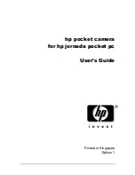
VCR PWB   Component Side SIDE B

Summary of Contents for VIEWCAM VL-A10H

Page 1: ...OARD ASSEMBLIES 82 10 REPLACEMENT PARTS LIST 93 11 PACKING OF THE SET 111 S30Y3VL A10S SERVICE MANUAL LIQUID CRYSTAL CAMCORDER Hi 8 PAL CONTENTS SHARP CORPORATION In the interests of user safety Required by safety regula tions in some countries the set should be restored to its original condition and only parts identical to those specified be used MODELS SERVICE MANUAL MODELS VL A10S H E AH30S H E...

Page 2: ...d Audio Output Level 8 dBs impedance less than 2 2 kohms Speaker Output 200 mW Power Requirement DC 3 6V with battery pack DC 7 0V with AC adapter Power Consumption 4 9W during camera recording in full auto mode with zoom motor off and backlight in normal mode Operating Temperature 0 C to 40 C Operating Humidity 30 to 80 Storage Temperature 20 C to 60 C Dimensions approx 183 mm W 109 mm H 99 mm D ...

Page 3: ...loop Lithium battery holder Cassette compartment door release Cassette compartment door Speaker Rear view Bottom view Shoulder strap loop Hand strap RECord START STOP button Battery compartment door CHARGE indicator MENU button Remote sensor LCD monitor screen Tripod socket Power switch CAMERA VCR select switch DISPLAY button Operation buttons Power Zoom Wide angle Telephoto control VOLume control...

Page 4: ...and pull out the camera rear cabinet 2 backwards Remove the FPC in the camera rear cabinet b d Connector a a Pull out 2 Camera rear cabinet 1 2 6 Remove two screws b LX HZ0018TAFF and pull out the camera side cover from the tilt frame C Tilt frame C b b Pull out 9 After removing the camera PWB from the tilt frame remove the connector on the rear of the PWB Connector 8 Remove one connector of the c...

Page 5: ...CR lid VCR lid shaft VCR lid Frame V VCR lid shaft Detail of area A 2 Bring the jig example slotted precision screwdriver into contact with the removal groove of the VCR lid shaft and slide the screwdriver with care to prevent injuring the VCR lid and frame V 1 Remove one screw k LX HZ0063TAFC 2 Remove five screws b LX HZ0018TAFF 3 Turn the tilt frame C so that the screwdriver can be easily insert...

Page 6: ...ne connector 3 Remove the microphone wire spacer from the Frame V Wirefixingtape 4 Pull out the microphone wire cable with care to prevent it from interfering with the mechanical parts and remove the VCR lid Pull out Area B Microphone connector AV unit wire AV unit FPC b b 4 Removal of the AV unit and AV unit cover 5 Disassembly of the LCD holder Tripod angle b b b 1 Peel the wire fixing tape 2 Re...

Page 7: ... the cassette compartment lid Note Take care to prevent breaking the claws of the cassette com partment lid B D Frame V Connector 1 Remove three screws e LX BZ0191TAFD and one con nector and remove the frame V from the main body 1 Disconnect three connectors Remove the tilt unit from the cabinet of the main body 3 Remove two screws b LX HZ0018TAFF and two connec tors and remove the LCD unit with i...

Page 8: ...claw B and slide the LCD panel 4 in the C direction to remove the LCD holder 2 Note When handling the prism sheet diffusion sheet light guide plate reflection sheet and reflection polarizing sheet do not touch any parts other than lugs and sides Put the light guide plate and reflection sheet between reflectors of lamp Therefore install them together with the lamp ass y Note When fixing the cassett...

Page 9: ...ws 6 LX HZ0013TAFF 4 Mount the sensor PWB so that the CCD sensor leads go thorough the PWB holes 5 Solder the CCD sensor lead to the sensor PWB Note Take care not to apply excessive heat Rubber Lens Side CCD Side The THIN SIDE faces the lens Crystal CCD Sensor Sensor Holder 6 Mark The mark must be on this face 3 3 REPLACEMENT OF CCD SENSOR 3 3 1 BEFORE REPLACEMENT 1 The CCD image sensor is more se...

Page 10: ...onscrew drivers Phillipshead slotted head 3 Radiopliers withthin jaws 4 A pair of tweezers Note The entries of list Configuration 1 Name 2 Part No 3 Code Model Uses Remarks 1 Cassette torquemeter for PB 2 JiG8T 012 3 CV 10 g cm 25 g cm 1 Cassette torquemeter for VS REW 2 JiG8T 032 3 CV 50 g cm 25 g cm 1 Torque gauge 2 JiGTG0045 3 CN For measurement of loading brake torque 1 Torque gauge head 2 JiG...

Page 11: ...her cleaning or replacing the parts is required 3 Oils a Be sure to use the specified oils different viscosity may cause troubles b For the bearings be sure to use oil that is free form dust and other foreign substances Dust or foreign substance contained in the oil may cause wear or seizure of the bearings c A drop of oil represents the amount of oil which is held on the needle top as shown in th...

Page 12: ...e S Tu reel disk is within the specified range Figure 2 Note When measuring do not apply excessive force to the reel support surface of reel disk 4 If the measurement is not within the specified range replace the reel disk ass y 5 Check the items 2 to 4 above in the following two modes a Standby mode b Playback recording mode 4 3 2 Checking the take up torque for playback recording 1 Set the torqu...

Page 13: ...s not in the specified position repeat the adjusting procedure 1 thru 3 Note Tightening torque of screw a 70 mN m To check the position be sure to run the tape If the cassette compartment assembly is removed it makes the work easier Refer to Item 5 5 3 3 0 5 0 Si roller Tension pole T Band Holder B Screw a B Hole C A 4 3 5 Checking the take up torque for rewind playback VS REW 1 Remove the cassett...

Page 14: ...ded on the lower flange B of Si roller Figure 4 If tape folding is found turn the upper flange A of Si roller with the driver clockwise to eliminate the folding 3 Playback the alignment tape VR2DBOPS 4 Adjust the Sup GR and Tu GR by the procedure described in section 4 2 above 5 After V S F R perform playback so as to ascertain that the waveform rises horizontally within 2 seconds 6 Unless the nor...

Page 15: ...n that the envelope maximum to minimum ratio is 65 or more Figure 9 3 Ascertain that the waveform does not change remarkably Figure 10 Figure 10 EMAX EMIN EMAX EMIN 65 Figure 9 A C C C 1 8A 2 Rise check 1 Playback the alignment tape VR2DBOPS 2 Once eject the cassette and then load it again 3 Set the playback mode and ascertain that the RF waveform rises horizontally within 2 seconds At this time a...

Page 16: ...ow is given an explanation of the mechanism mode necessary for mechanism check adjustment and replacement 1 EJ Eject mode See Figure 1 In this mode it is mechanically positioned to eject the cassette It is the position where the EJECT lever is moved the farthest in the direction A in the S B mode In this mode the cassette compartment assembly can not be locked 2 S B Standby mode See Figure 2 When ...

Page 17: ...ide chassis slits e and slide them until they reach the slits 4 Attach the down guide While pressing the guide in the direction i tighten the screws until the gap j between the down guide3 and the support shafts c becomes zero Tightening torque 70 7 mN m 0 7 0 07 kg cm Screw tightening torque 4 locations 0 069 0 007 N m 0 7 0 07 kg cm c i b j a Lock Lever Down Guide Screw Figure 5 Lock lever secti...

Page 18: ...tary transformer rotor ass y former type Remove the 2 rotor mounting screws as shown in Figure 4 a and remove the motor rotor and the rotary trans former ass y 4 b Motor rotor ass y bonded type Remove two screws fix ing the rotor as shown in Figure 4 b then remove only the motor rotor Balancer mounting screw Balancer Upper drum ass y Figure 5 Motor rotor Positioning hole Upper drum ass y Rotor mou...

Page 19: ...traight section when it is installed on the chassis Figure 9 6 Drum base Align the positioning pin and tighten the screws 3 pcs 7 Drum ass y Install the drum ass y on the main chassis and tighten the screws 3 pcs 8 Tape guide Align the positioning pin and tighten the screw one pc Motor stator Stator set screw Figure 9 4 5 5 Phase matching The phase of the following parts must be matched as shown i...

Page 20: ...bly taking care to position it correctly Make sure not deform the arm A a A C D B Segment gear Su arm Ass y T Lo arm Ass y Square Hollow Mark Triangle Mark Edge A Round Hole Align the marks on the parts a A a a a Loading motor Drive gear Position the small gear of the drive towards the chassis Capstan motor Move FF downwards Install the motor under this plate Item Tightening torque Quantity A S Ti...

Page 21: ... base Insert the main cam pin into the hole of cam of slide chassis Item Tightening torque Quantity A S tight M1 4 x 2 5 70mN m 1 B CW ø0 8 ø3 t0 2 70mN m 1 Take care not to bend the tension band during assembly or disassembly Pinch lever Tu guide lever Tu guide lever SPR Attach to hook Attach to hook Take care of position Pinch lever Stopper The pinch lever is positioned on the stopper Secure on ...

Page 22: ...ecks owning to their small sizes Therefore exercise due care to avoid long time exposure of the pins of these parts to the heat of the soldering iron which may possibly damage them Such care should be exercised especially for chip layer capacitor replacement It is advisable to use a temperature controlled ceramic soldering iron temperature at the tip 250 C contacting time less than 5 seconds 5 2 A...

Page 23: ...art No 3 Code 4 Note Model Uses Remarks 5 3 2 1 Typical connections Extension Cable etc 1 Extension Cable LCD VCR 24pin 2 QCNW 1382TAZZ 3 BD 1 Extension Cable Inverter VCR 7pin 2 QCNW 1265TAZZ 3 AX 1 Extension Cable Camera VCR 20pin 2 QCNW 1774TAZZ 3 BH 1 Extension Cable Camera VCR 24pin 2 QCNW 1382TAZZ 3 BD 1 Extension Cable MECHA VCR 70pin 2 QCNW 1534TAZZ 3 BS 1 2 3 4 5 6 7 8 1 Service remote co...

Page 24: ...m check error display The difference between the preset battery alarm voltage and the current supply voltage is displayed as follows A past error is displayed at the right of the current battery alarm error 4 TEST No 5 PASS mode Used to adjust the tape travelling condition The tracking is shifted by 1 4 from the center to make the tape running related RF envelope fluctuations easier to observe 5 T...

Page 25: ...01 on the LCD OSD 01 flashing and select the below TEST No with FF or REW key and set with PLAY key Same procedures of adjustment from now on Use the SW2 thru SW9 switches on the adjustment tool to select the following test modes TEST No Title Contents Sensor on off 1 Sensors off All sensors but the cassette controller switch dew sensor and battery sensor stay off 2 Mechanism adjustment 1 Automati...

Page 26: ...ain that the digital voltmeter indicates 2 5V 0 1V Measuring instrument Digital voltmeter Measuring terminal TL916 Adjustment address Standard 2 5V 0 1V 2 Checking of P CON 4 9V Ascertain that the digital voltmeter indicates 4 9V 0 1V POWER CIRCUIT ADJUSTMENT METHOD Æ Input 7V from DC Jack and set the power switch to the camera side Don t fail to fix the back light unit before adjusting them 6 Che...

Page 27: ...54 2 Play back the alignment tape JiGWR5 5CSP 3 Press the CONTINUOUS PUSH and VCR ADJUSTMENT of adjustment remote controller to set the VCR adjustment mode Mode Address Measuring point Adjustment standard Measuring instrument 3F ME 160 5mVP P 40 MP 115 5mVP P 41 ME 165 5mVP P 42 MP 135 5mVP P REC Y current adjustment Hi 8 REC Y current adjustment Nor 8 VCR STOP Oscilloscope TL9413 Sig TL9414 Gnd M...

Page 28: ...e Mode REC PB Input signal tape 400 Hz 8 dBs 872 mVp p Measuring terminal Audio IN OUT Adjustment address Set value 8 dBs 4 dBs 580 to 1370 mVp p 2 Dac full Scalle adjustment Measuring point TL1801 G OUT Address 039 Mode VCR Adjusting method 1 Set the data of address 082 changed to 80 address 0A2 changed to 00 address 0A5 changed to 80 2 Connect TL3804 to P CON 3 1V 3 Connect the Digital voltmeter...

Page 29: ... and address 082 at the address A9 2 Set the illuminometer TOPCON IM 3 on the LCD panel surface do not allow entry of external light 3 Connect the illuminometer to the oscilloscope 4 Make an adjustment so as to minimize the ripple of output waveform Response time 0 6 sec 5 Adjust again if longitudinal stripe appears evidently 6 Set data of address 082 at the address 40 Restore Or set to the point ...

Page 30: ...er 2 JiGHOYA LB165 3 BN 1 Service Remote Control 2 RRMCG0033TASA 3 BT 1 Gray Scale Chart 390 x 520 mm 2 JiGCHART 1 3 CP Connections for Camera Section Servicing 5 4 2 Adjustment procedures This adjusting procedure covers all the steps for conducting the adjustments all the way There are some steps that may be skipped depending on the specific needs for servicing and adjustment 1 Checking the power...

Page 31: ...ng instrument None Subject More than 50 m away Tape Test point None Adjustment address 71 Adjustment level 12 06 08 0D DATA Adjustment 12 Optical wide end adjustment 06 Wide end focus position adjustment 08 Tele end focus position adjustment 0D Zoom tracking adjustment 1 Set up the auto focus adjustment mode This is unnecessary after the above basic iris adjustment has been made 2 Write the adjust...

Page 32: ...B MAT 343 2 1 Usingtheaddress1C4 adjusttheRleveltoaburstratioof1 4 With the address 1C2 adjust the B level to a burst ratio of 1 0 2 Using the address 1C0 adjust the R phase to 104 With the address 1BE adjust the B phase to 343 3 Repeat the above steps 1 and 2 Measuring instrument Vector scope Subject Gray scale Tape Test point VIDEO OUT Terminated in 75 Ω Adjustment address R OUT DOOR 6C B OUT DO...

Page 33: ...layback Check the ATF circuit û No recorded characters on screen YES ChecktheLCDcircuitandcharactergenerator IC705 û YES No color in EE mode Check the camera section and Y C circuit û YES No color in playback û YES û YES û YES û Black streaking No sound Check the Y C circuit and head amplifier circuit Check the audio circuit Check the system controller and CAP MOTOR DRIVER circuit Check the Y C ci...

Page 34: ...t of I chip µ computer IC551 Lens driver and their peripherals û Normal No power zoom function 5 5 3 Charging mode troubles Start Check the circuit of SYSCON Check the circuit of SYSCON Check Q2911 R2914 R2915 and battery terminal unit Battery is defective Check the AC adapter Check Q2905 IC2901 and around the circuits Is ADP DET H 1 Is CHG ON L or H 2 Is BAT DET OV Is BAT DET CK voltage more than...

Page 35: ...memory that serves to store the adjustment data of the camera section 4 The other circuits and ICs are under the L H level or the PWM control BATTERY NONREGE IC900 IC2 DSP IC401 IC601 IC3801 IC2701 D A IC706 IC705 POWER CAMERA E2 PROM LENS E2 PROM SERIAL BUS CAM Y C ATF CAM HEAD AUDIO SERVO CIRCUIT H A UNIT MECHA NISM MECHA CHASSIS POWER SIGNAL POWER MOTOR SYSTEM SERVO CONTROL KEY 3 0V Reg POWER A...

Page 36: ...L FL BF TL407 117 23 19 Q410 FL IC706 IC601 IC601 17 118 IC601 IC706 Q707 IC708 MIX AMP PEAKING AMP IC101 CDS AGC 8 32 31 25 26 4 øV øH H V IC11 V DRIVER IC12 TG IC1 Lens CCD SENSOR FL FL NC FL TL801 GIN RIN R OUT G OUT B OUT BIN TL800 TL802 Q1401 Q1403 Q1402 Q1404 8 1 5 IC1451 DRIVER IC800 11 CN3601 TL1451 7 6 8 24 9 22 10 20 11 CN3800 CN7401 SC305 Q307 TL3813 TL3814 TL3815 BUF FL EQ EQ EQ BUF EN...

Page 37: ...CH 2 VIDEO HEAD R CH 1 ROTALYTRANSFORMER Q315 Q302 13 PB RF EVN 24 H SW P 23 OVER P 28 REC Y 31 REC C 16 AGC IN 19 PB Y FM 22 D O PULSE SC305 34 REC RF 10 ROT ERASE BUF BUF VGC 11 3 Q315 2 30 9 28 9 7 5 32 4 FF30 Y AMP AGC DOC PLAYBACK AMPLIFIER CH 2 RECORDING AMPLIFIER CH 2 ERASING OSCILLATOR SWITCH ERASING OSCILLATOR PLAYBACK AMPLIFIER CH 1 24 27 13 a 1 FE S SC301 5 L S SC301 6 L F SC301 9 R S S...

Page 38: ... Drive circuit Voltage drop Standard power 1 2 3 4 5 6 7 8 DRUM ERROR CAP ERROR B L CTL 3 3V Power Rise and fall voltage circuit PNP Tr 4 9V Power Rise and fall voltage circuit PNP Tr Mecha 5V Rise and fall voltage circuit PNP Tr B L POW Rise and fall voltage circuit PNP Tr 2 8V Power Valtage drop circuit PNP Tr DRUM VS Valtage drop circuit PNP Tr CAP VS Valtage drop circuit PNP Tr Trans circuit N...

Page 39: ... at DC input NON REG Q2903 SYS 3 0V REG circuit ADP DET BATT DET Charging Red light up Completion Green light up CHARGE ON_H PRE CHARGE ON Charge control IC Vcc SW1 SW2 MM1332G LV GND EXT CEL CS 8 1 7 2 3 4 6 5 LED Red LED Green LED_G LED_R T Ni MH battery System microcomputer Vcc DC input lived DC input ON OFF detection Battery voltage detection BATT TEMP T Terminal detection BATT IN VCR H Q2901 ...

Page 40: ... OFFSET IRIS L IRIS H IC151 A D IC101 CDS AGC ZOOM LENS MASTER LENS IRIS METER Device M IC551 LENS DRIVER FO2 FO2 FO1 FO1 M FOCUS MOTOR Master Lens POSI ZOOM LENS POSI ZOOM MOTOR M ZO1 ZO1 ZO2 ZO2 16 14 10 12 CLK DATA 35 34 LATCH VD 33 32 ZOOM MOTOR DRIVE PHIRZ HALL OUT 28 30 26 24 IRIS FOCUS ZOOM CONTROL LENS DATA2 DATA CLK CS HALL IN FOCUS MOTOR DRIVE 124 10 IC553 OP AMP 6 7 IC552 OP AMP 8 3 13 ...

Page 41: ...41 VL A10S H E VL AH30S H E M E M O ...

Page 42: ...1 2 3 4 5 6 7 8 9 10 11 12 13 14 15 16 17 18 19 20 A B C D E F G H I J VL A10S H E VL AH30S H E 42 43 7 SCHEMATIC DIAGRAMS 7 1 OVERALL SCHEMATIC DIAGRAM ...

Page 43: ...1 2 3 4 5 6 7 8 9 10 11 12 13 14 15 16 17 18 19 20 A B C D E F G H I J VL A10S H E VL AH30S H E 44 45 7 2 ADC SCHEMATIC DIAGRAM ...

Page 44: ...1 2 3 4 5 6 7 8 9 10 11 12 13 14 15 16 17 18 19 20 A B C D E F G H I J VL A10S H E VL AH30S H E 46 47 7 3 DSP SCHEMATIC DIAGRAM ...

Page 45: ...1 2 3 4 5 6 7 8 9 10 11 12 13 14 15 16 17 18 19 20 A B C D E F G H I J VL A10S H E VL AH30S H E 48 49 7 4 AUDIO SCHEMATIC DIAGRAM ...

Page 46: ...4 5 6 7 8 9 10 11 12 13 14 15 16 17 18 19 20 A B C D E F G H I J VL A10S H E VL AH30S H E 50 51 A10 AH30 R4703 Yes No R4704 Yes No R731 No Yes R732 No Yes C705 No Yes C707 No Yes 7 5 SYSCON SCHEMATIC DIAGRAM ...

Page 47: ...1 2 3 4 5 6 7 8 9 10 11 12 13 14 15 16 17 18 19 20 A B C D E F G H I J VL A10S H E VL AH30S H E 52 53 7 6 LCD_INT SCHEMATIC DIAGRAM ...

Page 48: ...1 2 3 4 5 6 7 8 9 10 11 12 13 14 15 16 17 18 19 20 A B C D E F G H I J VL A10S H E VL AH30S H E 54 55 7 7 LCD_CTL SCHEMATIC DIAGRAM ...

Page 49: ...1 2 3 4 5 6 7 8 9 10 11 12 13 14 15 16 17 18 19 20 A B C D E F G H I J VL A10S H E VL AH30S H E å 56 57 å AND SHADED COMPONENTS SAFETY RELATED PARTS 7 8 POWER SCHEMATIC DIAGRAM ...

Page 50: ...1 2 3 4 5 6 7 8 9 10 11 12 13 14 15 16 17 18 19 20 A B C D E F G H I J VL A10S H E VL AH30S H E 58 59 7 9 I O SCHEMATIC DIAGRAM ...

Page 51: ...1 2 3 4 5 6 7 8 9 10 11 12 13 14 15 16 17 18 19 20 A B C D E F G H I J VL A10S H E VL AH30S H E 60 61 7 10 SYSDAC SCHEMATIC DIAGRAM ...

Page 52: ...1 2 3 4 5 6 7 8 9 10 11 12 13 14 15 16 17 18 19 20 A B C D E F G H I J VL A10S H E VL AH30S H E å å å 62 63 å AND SHADED COMPONENTS SAFETY RELATED PARTS 7 11 CHARGE SCHEMATIC DIAGRAM ...

Page 53: ...1 2 3 4 5 6 7 8 9 10 11 12 13 14 15 16 17 18 19 20 A B C D E F G H I J VL A10S H E VL AH30S H E 66 67 7 13 RF SCHEMATIC DIAGRAM VL AH30 ...

Page 54: ...1 2 3 4 5 6 7 8 9 10 11 12 13 14 15 16 17 18 19 20 A B C D E F G H I J VL A10S H E VL AH30S H E 68 69 7 14 TG SCHEMATIC DIAGRAM ...

Page 55: ...1 2 3 4 5 6 7 8 9 10 11 12 13 14 15 16 17 18 19 20 A B C D E F G H I J VL A10S H E VL AH30S H E 70 71 7 15 CDS SCHEMATIC DIAGRAM ...

Page 56: ...1 2 3 4 5 6 7 8 9 10 11 12 13 14 15 16 17 18 19 20 A B C D E F G H I J VL A10S H E VL AH30S H E 72 73 7 16 LDRV SCHEMATIC DIAGRAM ...

Page 57: ...1 2 3 4 5 6 7 8 9 10 11 12 13 14 15 16 17 18 19 20 A B C D E F G H I J VL A10S H E VL AH30S H E 74 75 7 17 HEAD AMP SCHEMATIC DIAGRAM ...

Page 58: ...1 2 3 4 5 6 7 8 9 10 11 12 13 14 15 16 17 18 19 20 A B C D E F G H I J VL A10S H E VL AH30S H E 76 77 7 18 MOTOR DRIVER SCHEMATIC DIAGRAM ...

Page 59: ...1 2 3 4 5 6 7 8 9 10 11 12 13 14 15 16 17 18 19 20 A B C D E F G H I J VL A10S H E VL AH30S H E 78 79 7 19 CCD SCHEMATIC DIAGRAM ...

Page 60: ... A NC A C C D G S C A A C A A C 2 A C C 3 1 4 A MA704WA DAN222 SI2301DS DA121 DA227 DA221 MA147 MA133 1 2 3 NJM79L09 1 2 3 4 PST592KM DTA144EE CPH3209 CPH3109 RT1P241U RT1P441U RT1N241U RT1N141N RT1P140U RT1N140U RN1902 RN1903 RN1904 CPH6303 HN1B04FU HN1A01FU HN2A01FU HN1C01FU HN2C01FU RN4982 RN4983 RN4984 RN4990 RN2902 RN2903 RN2904 UMB2 UMD12N UMT2 UMX2 UPUMZ1 XP6501 3 4 5 6 2 1 A C C C A A UMR1...

Page 61: ... 25 19 92 80 72 60 50 40 36 32 28 24 18 47 41 37 31 26 21 19 17 15 13 10 1 36 48 56 64 72 80 100 120 144 160 184 28 37 43 49 55 61 76 91 109 121 139 9 12 14 16 18 20 25 30 36 40 46 IX0604TA IX0629TA IX0630TA IX0625TA IX0608TA IX0620TA M5412450 S84235F S24C02A TA75W558 MM1332G TC7W14U TC7W74U TC7W74U TC7W08U TC4W53U 24LC8BIN TC7WH74U TC7W66U 1 8 5 4 IX0494TA 1 14 28 15 IX0560TA 1 8 5 4 1 4 8 5 S842...

Page 62: ...R488 TL402 C469 C447 C448 C444 R458 R461 R447 TL405 C440 C471 R464 L405 Q409 R463 R456 R4400 R3836 C3811 C3814 R923 R919 R920 R925 R924 R3835 C3810 R3845 R3848 R3833 C3809 C930 R3831 R3826 R921 IC3802 R3824 R3823 R926 IC902 R3844 R3822 R916 R3820 L3802 C3808 R3821 R918 C3806 R911 C3805 C3807 R3816 R917 R913 R914 R915 R912 L3801 R3817 R3812 C152 C3803 C156 C154 C153 C151 L152 C155 D3800 L151 R1822 ...

Page 63: ...83 A B C D E F G H I J 1 2 3 4 5 6 7 8 9 10 VL A10S H E VL AH30S H E VCR PWB Wiring Side SIDE A ...

Page 64: ... TL7436 Q8452 R1406 R1405 TL7416 TL7435 TL7409 TL7434 R1401 TL7417 TL422 TL7425 TL7433 TL7432 R8461 R8459 TL7418 TL7419 TL7438 C8457 R8457 TL7420 TL7431 R8466 TL7405 TL7421 TL7430 C704 C8455 TL713 TL7422 TL7424 TL7429 TL714 R787 TL7426 TL712 Q403 TL7427 TL715 TL7428 R412 C474 R4704 R742 R406 C707 C722 R732 R716 C705 R744 R731 R4703 R715 R730 C703 R714 TL748 R719 C701 R703 R778 R780 R775 R718 C706 ...

Page 65: ...85 A B C D E F G H I J 1 2 3 4 5 6 7 8 9 10 VL A10S H E VL AH30S H E VCR PWB Wiring Side SIDE B ...

Page 66: ...R128 R129 R131 R132 R135 R137 TL115 R133 R139 TL30 TL121 R134 TL122 R138 TL31 C563 C38 L553 L13 L12 L551 C29 R34 R31 C26 TL25 Q12 C17 R30 C25 R28 R27 C24 R19 R26 R24 R14 Q11 R15 IC12 R20 TL22 C20 C21 R22 C12 TL27 R16 TL23 TL28 C18 R21 R11 R13 R12 TL29 TL20 TL19 TL26 L101 C108 SC11 C113 TL101 TL21 TL18 TL16 TL15 TL13 TL11 C111 TL17 TL14 TL12 TL24 C11 C565 TL551 TL552 TL553 TL554 TL561 TL555 TL562 T...

Page 67: ...87 A B C D E F G H I J 1 2 3 4 5 6 7 8 9 10 VL A10S H E VL AH30S H E CAMERA PWB Wiring Side SIDE A ...

Page 68: ...B110 R111 R115 R119 R114 R112 FB109 TL143 TL147 TL137 TL138 TL142 R113 SC103 TL140 TL141 R149 TL139 D551 R577 R584 R575 C570 R578 R564 R561 C567 IC552 TL150 R122 TL149 TL148 R565 R566 R567 C569 R568 C572 R571 R120 R121 C553 R589 R583 R569 R562 IC553 R587 R579 C573 IC554 R586 C571 R563 R585 R572 C568 C574 R102 R101 C103 C105 R104 TL102 R105 R103 C107 R107 R108 R106 C109 TL136 C112 IC101 R148 C110 C...

Page 69: ...89 A B C D E F G H I J 1 2 3 4 5 6 7 8 9 10 VL A10S H E VL AH30S H E CAMERA PWB Wiring Side SIDE B ...

Page 70: ...303 L304 L305 TL305 TL3739 TL3740 TL3742 TL3744 TL3745 TL3746 TL3749 TL3747 TL3720 TL3750 TL3748 TL3751 TL3741 TL3743 L3702 TL3719 Z1 L3701 TL3718 TL3702 TL3701 TL3706 SC305 TL307 C3731 C3730 C3729 TL308 R3729 TL310 R3728 R3727 TL3724 TL3725 TL312 R3725 R3726 R3724 C3732 TL3716 TL319 TL3717 TL322 TL321 C3734 TL3723 C3733 TL3733 TL3731 TL3736 C3726 TL3728 TL3735 TL3734 TL3727 TL3738 TL3729 R3719 TL...

Page 71: ...91 A B C D E F G H I J 1 2 3 4 5 6 7 8 9 10 VL A10S H E VL AH30S H E HEAD AMP PWB Wiring Side SIDE A ...

Page 72: ...92 A B C D E F G H I J 1 2 3 4 5 6 7 8 9 10 VL A10S H E VL AH30S H E HEAD AMP PWB Wiring Side SIDE B ...

Page 73: ...VS2SC5383F 1 2SC5383F AB Q704 VSHN1B04FU 1 HN1B04FU AC Q705 VSHN2C01FU 1 HN2C01FU AC Q707 VSHN1C01FU 1 HN1C01FU AC Q708 VSRN2904 1 RN2904 AC Q709 VSHN1C01FU 1 HN1C01FU AC Q901 VS2SA2010 1 2SA2010 AD Q903 VS2SA1989R 1 2SA1989R AB Q904 VS2SA1362GR 1 2SA1362GR AC Q905 VS2SA1989R 1 2SA1989R AB Q906 VS2SA2010 1 2SA2010 AD Q908 VS2SA1362GR 1 2SA1362GR AC Q911 VSCPH3215 1 CPH3215 AD Q912 VS2SA1989R 1 2SA...

Page 74: ...EX L7403 VPD9M220J2R7N Peaking 22µH AC L7404 VPBBM471J310N Peaking 470µH AB L7405 VPD9M221J210N Peaking 220µH AB L7406 VPBBM331J260N Peaking 330µH AB L7407 VPD9M330J3R6N Peaking 33µH AC AH30S H E EX L7408 VPBBM331J260N Peaking 330µH AB L7452 VPD9M8R2J2R0N Peaking 8 2µH AC L7453 VPD9M8R2J2R0N Peaking 8 2µH AC AH30S H E EX L8401 VPD9M1R8JR84N Peaking 1 8µH AC L8402 VPD9M2R2JR96N Peaking 2 2µH AC Q29...

Page 75: ...47 6 3V Electrolytic AB C604 VCSATE1AJ476M 47 10V Tantalum AD C605 VCKYCZ1CB103K 0 01 16V Ceramic AB C606 VCKYCZ1CB103K 0 01 16V Ceramic AB C607 VCKYCZ1CB103K 0 01 16V Ceramic AB C608 VCKYCZ1CB103K 0 01 16V Ceramic AB C609 VCKYCY1CF334Z 0 33 16V Ceramic AA C610 VCKYCZ1CB103K 0 01 16V Ceramic AB C611 VCEAPF0JW226M 22 6 3V Electrolytic AB C612 VCEAPH1HW474M 0 47 50V Electrolytic AB C613 VCKYCZ1CB103...

Page 76: ...903 VCKYCZ1AB104K 0 1 10V Ceramic AB C1904 VCKYCZ1AB104K 0 1 10V Ceramic AB C1907 VCKYCZ1AB473K 0 047 10V Ceramic AB C1908 VCKYCZ1AB104K 0 1 10V Ceramic AB C1909 VCKYCZ1AB104K 0 1 10V Ceramic AB C1910 VCKYCZ1AB104K 0 1 10V Ceramic AB C1911 VCKYCZ1AB104K 0 1 10V Ceramic AB C1912 VCCCCZ1HH101J 100p 50V Ceramic AB C1913 VCKYCY1AB224K 0 22 10V Ceramic AB C1914 VCKYCZ1HB102K 1000p 50V Ceramic AB C1915 ...

Page 77: ... Metal Oxide AA R731 VRS CZ1JF104J 100k 1 16W Metal Oxide AA AH30S H E EX R732 VRS CZ1JF104J 100k 1 16W Metal Oxide AA AH30S H E EX R733 VRS CZ1JF822J 8 2k 1 16W Metal Oxide AA R734 VRS CZ1JF822J 8 2k 1 16W Metal Oxide AA R735 VRS CZ1JF102J 1k 1 16W Metal Oxide AA R737 VRS CZ1JF334J 330k 1 16W Metal Oxide AA C7409 VCKYCZ1CB103K 0 01 16V Ceramic AB C7410 VCCCCY1HH221J 220p 50V Ceramic AA C7411 VCCC...

Page 78: ...Z1JF183J 18k 1 16W Metal Oxide AA R1913 VRS CZ1JF105J 1M 1 16W Metal Oxide AA R1914 VRS CZ1JF103J 10k 1 16W Metal Oxide AA R1915 VRS CZ1JF333J 33k 1 16W Metal Oxide AA R738 VRS CZ1JF104J 100k 1 16W Metal Oxide AA R740 VRS CZ1JF473J 47k 1 16W Metal Oxide AA R741 VRS CZ1JF104J 100k 1 16W Metal Oxide AA R742 VRS CZ1JF103J 10k 1 16W Metal Oxide AA R743 VRS CZ1JF152J 1 5k 1 16W Metal Oxide AA R744 VRS ...

Page 79: ...Metal Oxide AA R2416 VRS CZ1JF561D 560 1 16W Metal Oxide AA R2417 VRS CZ1JF183D 18k 1 16W Metal Oxide AB R2418 VRS CZ1JF102J 1k 1 16W Metal Oxide AA R2419 VRS CZ1JF102J 1k 1 16W Metal Oxide AA R2420 VRS CZ1JF222J 2 2k 1 16W Metal Oxide AA R2421 VRS CZ1JF222J 2 2k 1 16W Metal Oxide AA R2423 VRS CZ1JF102J 1k 1 16W Metal Oxide AA R2901 VRS CZ1JF105J 1M 1 16W Metal Oxide AA R2902 VRS CZ1JF122J 1 2k 1 ...

Page 80: ...6W Metal Oxide AA R7426 VRS CZ1JF271J 270 1 16W Metal Oxide AA R7451 VRS CZ1JF102J 1k 1 16W Metal Oxide AA R7454 VRS CZ1JF000J 0 1 16W Metal Oxide AA R7455 VRS CZ1JF000J 0 1 16W Metal Oxide AA R7456 VRS CZ1JF152J 1 5k 1 16W Metal Oxide AA R7459 VRS CZ1JF391J 390 1 16W Metal Oxide AA R7460 VRS CZ1JF271J 270 1 16W Metal Oxide AA R7461 VRS CZ1JF000J 0 1 16W Metal Oxide AA A10S H E EW EX R7461 VRS CZ1...

Page 81: ... 1 10V Ceramic AB C119 VCKYCZ1HB471K 470p 50V Ceramic AB C120 VCKYCZ1AF104Z 0 1 10V Ceramic AB C551 VCKYCZ1HF103Z 0 01 50V Ceramic AB C552 VCKYCZ1HF103Z 0 01 50V Ceramic AB C553 VCKYCZ1HF103Z 0 01 50V Ceramic AB C554 VCCCCZ1HH330J 33p 50V Ceramic AB C555 VCKYCZ1HF103Z 0 01 50V Ceramic AB C556 VCKYCZ1HF103Z 0 01 50V Ceramic AB C558 VCKYCZ1HF103Z 0 01 50V Ceramic AB C559 VCKYCZ1HF103Z 0 01 50V Ceram...

Page 82: ...Z1JF000J 0 1 16W Metal Oxide AA R307 VRS CZ1JF000J 0 1 16W Metal Oxide AA R308 VRS CZ1JF392J 3 9k 1 16W Metal Oxide AA R313 VRS CZ1JF183J 18k 1 16W Metal Oxide AA R316 VRS CZ1JF103J 10k 1 16W Metal Oxide AA R317 VRS CZ1JF103J 10k 1 16W Metal Oxide AA R321 VRS CZ1JF152J 1 5k 1 16W Metal Oxide AA R323 VRS CZ1JF473J 47k 1 16W Metal Oxide AA R329 VRS CZ1JF471J 470 1 16W Metal Oxide AA R331 VRS CZ1JF10...

Page 83: ...9 VRS TV1JD1R0J 1 1 16W Metal Oxide AA R3720 VRS TV1JD1R0J 1 1 16W Metal Oxide AA R3721 VRS CZ1JF473J 47k 1 16W Metal Oxide AA R3722 VRS CZ1JF102J 1k 1 16W Metal Oxide AA R3723 VRS CZ1JF105J 1M 1 16W Metal Oxide AA R3724 VRS CZ1JF103J 10k 1 16W Metal Oxide AA R3725 VRS CZ1JF102J 1k 1 16W Metal Oxide AA R3726 VRS CZ1JF102J 1k 1 16W Metal Oxide AA R3727 VRS CZ1JF473J 47k 1 16W Metal Oxide AA R3728 V...

Page 84: ... Si Roller Ass y AG 364 QPWBH5428GEZZ Mode FPC AK 365 CPWBN5877GE01 Sensor Ass y AT 366 QSW M0042GEZZ Recognition SW AH 367 RDTCH0037GEZZ Dew Sensor AF 368 RMOTV1020GEZZ Capstan Motor AZ 369 RMOTM1075GEZZ Load Motor AL 370 QSW R0038GEZZ Mode SW AG 372 DUNTK2936QA01 H A PWB 374 TLABH0584GEZZ Caution Label AB 375 PSHEM0014GEZZ Counter Balance AC 376 PSHEP0013GEZZ Interruption Sheet AC 200 XAPSF17P03...

Page 85: ...25 QTANZ0146TAZZ Battery Terminal Unit AK 26 QSW Z0285TAZZ Power Zoom Unit AR 27 LHLDZ1452TAZZ Power Lock Holder AC 28 MSPRC0083TAFJ Power Lock Spring AA 29 JBTN 0277TASA Power Button AD A10S H E EW EX 29 JBTN 0277TASB Power Button AF AH30S H E EX 30 LHLDZ1451TAZZ Power Holder AC 31 JKNBP0152TASA Power Knob AD 32 JKNBP0153TASA Zoom Knob AD A10S H E EW EX 32 JKNBP0153TASB Zoom Knob AF AH30S H E EX ...

Page 86: ...20TAZZ Operation Manual 1 AW AH30S TiNSL0221TAZZ Operation Manual 2 AW AH30S TiNSL0225TAZZ Operation Manual 1 A10S AW TiNSL0226TAZZ Operation Manual 2 A10S AW å UADP 0313TAZZ AC Adapter BD UBNDS0010TASA Shoulder Strap AH GCOVH1234TAZZ Sun Hood AV A10S H EX AH30S H EX UBATL0011TAZZ Lithium Battery AE UBATM0011TAZZ Battery BC QPLGA0010GEZZ AC Plug Converter AF A10E AH30E ACCESSORIES NOT REPLACEMENT ...

Page 87: ...H SPAKC7523TAZZ Packing Case A10E EX SPAKC7524TAZZ Packing Case A10EW SPAKC7525TAZZ Packing Case AH30S SPAKC7526TAZZ Packing Case AH30H SPAKC7527TAZZ Packing Case AH30E EX SPAKP6049TAZZ HOSO PP SSAKA0087TAZZ Polyethylene Bag A10H E EW EX AH30H E EX SSAKA0088TAZZ Polyethylene Bag A10S AH30S SPAKA6343TAZZ Packing ADD SPAKA6344TAZZ Packing ADD SPAKA6345TAZZ Packing ADD SPAKF0266TAZZ AC Adapter Packin...

Page 88: ...5 328 209 368 204 204 348 202 349 362 354 355 208 369 313 363 208 202 214 312 310 202 209 209 215 318 332 316 311 304 209 370 364 333 302 214 303 301 214 309 323 322 209 315 317 214 327 307 308 208 209 209 306 208 341 376 343 330 212 357 329 336 206 344 339 338 337 214 358 206 209 209 209 342 209 209 372 334 335 214 300 353 352 214 361 360 331 207 214 340 305 205 209 326 321 214 209 216 216 204 20...

Page 89: ... 47 4 2 33 30 31 4 6 b d d c b b 55 59 c c h 7 h b 25 b b b b b i 19 14 b 13 18 e d d 17 50 51 52 12 11 1 46 b 43 c 41 42 b 40 c e 48 47 c 32 49 39 c 5 36 62 35 54 34 38 37 c e 10 9 15 b 58 b a 57 56 60 b 8 i i 24 2 f f d b f 21 20 23 22 6 3 6 2 6 5 6 6 7 2 7 3 7 4 7 5 2 5 2 4 2 3 2 2 2 6 6 9 6 7 6 7 6 8 6 12 6 14 6 11 6 10 6 13 a a c g b b k 56 2 1 3 1 4 5 5 5 3 5 4 5 2 1 2 c 63 ...

Page 90: ...ion Code VL A10S H E VL AH30S H E CASSETTE HOUSING CONTROL UNIT EXPLODED VIEW A B C 1 2 3 4 5 6 A B C D 1 2 3 4 5 6 Face the thinner part toward the lens side Lens side CCD side The mark must be on the face Mark 4 5 6 2 1 3 CAMERA UNIT EXPLODED VIEW 403 402 401 401 400 ...

Page 91: ...ation Manual 2 A10S TiNSL0226TAZZ Operation Manual 2 10 Common parts UADP 0313TAZZ AC Adapter å 11 Common parts UBNDS0010TASA Shoulder Strap 12 A10S H EX AH30S H EX GCOVH1234TAZZ Sun Hood 13 Common parts UBATL0011TAZZ Lithium Battery 14 Common parts UBATM0011TAZZ Battery 15 A10E AH30E QPLGA0010GEZZ AC Plug Converter No Model Parts Code Description Remarks 16 A10EX AH30EX TGANE0050TAZZ Guarantee Ca...

Page 92: ...ita Tochigi 329 2193 Japan COPYRIGHT C 2000 BY SHARP CORPORATION ALL RIGHTS RESERVED No part of this publication may be reproduced stored in a retrieval system or transmitted in any form or by any means electronic mechanical photocopying recording or otherwise without prior written permission of the publisher TQ0869 S Apr 2000 Printed in JAPAN SA DS VL A10S H E VL AH30S H E ...

Reviews: