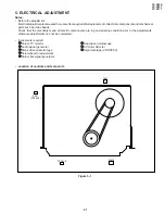
28
VC-V50S
VC-V80T
VC-V91T
Measuring
instrument
Mode
Cassette
Test point
VIDEO OUT jack to CH2
TP202(H.SW.P.)~TP203(GND)
to CH1
Control
Alignment tape(VROCPSV)
Playback
Dual-trace oscilloscope
R875 Head switching point
adjustment control
Specification
6.5
±
0.5H (lines)
1. Remove the front panel.
2. Set the COLOUR MODE switch turn on the PAL AUTO
mode, and play the alignment tape.(VROCPSV)
3. Connect a dual-trace oscilloscope to the VIDEO OUT
jack and TP202(H.S.P.)~TP203(GND).(Trigger the os-
cilloscope with the head switching pulse on TP202)
4. Playback the alignment tape, and then short circuit
between TP701 and TP702 on the main PWB, and press
both TRACKING buttons (+) and (–) on the remote
control at same time.
Be sure that the S.S. Picture LED flashing(about 2Hz)
into the TEST mode.
5. Cancel the short circuited of step-4.
6. Adjust R875 so that the leading edge of the head switch-
ing pulse is 6.5H (lines) a head of the vertical sync as
shown in Figure 5-2.
7. Press the STOP button in the return to normal mode.
Note:
When the models with both of PAL and NTSC function,
make of adjustment at PAL mode only.
Measuring
instrument
Mode
Cassette
Colour TV monitor
Playback still
Self-recorded tape (PAL)
(See Note below
1
)
SERVO CIRCUIT ADJUSTMENT
ADJUSTMENT OF HEAD SWITCHING POINT
ADJUSTMENT OF FV (False Vertical Sync) OF
STILL PICTURE
Figure 5-2.
6.5
±
0.5H
V: 2V/div
H: 50
µ
sec/div
CH-1
Head Switching Pulse
TRIG INT CH-1
CH-2
Video signal
Control
Tracking control buttons (+) or (–)
Specification
No vertical jitter of picture
1. Play an Alignment tape or a self-recorded tape.
2. Press the PAUSE/STILL button to freeze the picture.
3. Adjust (+) or (–) TRACKING buttons on the remote
control so that the vertical jitter of the picture is minimized.
Note:
1
Self-recorded tape is a tape which program was re-
corded by the unit being adjusted.
2
The FV goes back to the it's initial state when the unit is
put into the system controller reset mode due to power
failure, etc.
In this case, preset the FV once again.
1. Connect a 75 ohm terminating resistor to the VIDEO
OUT jack and connect an oscilloscope across this termi-
nating resistor.
(See Note below.)
2. Feed a colour bar signal to the VIDEO IN jack.
3. Make sure that the E-E signal amplitude is 1.0Vp-p as
shown in Figure 5-3.
Measuring
instrument
Mode
Input signal
Oscilloscope
E-E or Record
EIA colour bar (1.0Vp-p)
Test point
VIDEO OUT jack
Specification
1.0
±
0.2 Vp-p
1.0 Vp-p
Figure 5-3.
Y/C CIRCUIT ADJUSTMENT
CHECKING OF VIDEO E-E LEVEL
Notes:
If the 75 ohm terminating resistor is missing, the signal
amplitude will be doubled.

