background image

35

VC-SA350/350W
VC-SA355
VC-SA550/550W

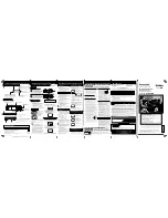
MECHANISM TROUBLESHOOTING

1. FF/REW FAILURE (NO TAPE WINDING)

Press FF key.

NO

NO

NO

NO

NO

NO

NO

NO

YES

YES

YES

YES

YES

YES

YES

YES

Is master cam at

FF position ?

Does loading

motor operate?

Modes changing

smoothly through

cam switch ?

Loading motor

control system

in trouble.

Are Vco 12V and

Vcc 5V applied ?

Replace the

capstan motor.

Replace the idler

ass’y.

Replace the reel

sensor.

Is voltage applied

to loading motor ?

Loading motor is

damaged. Replace

it.

Voltage supply

system in trouble.

Mode sensor

system in trouble

or master cam

malpositioned.

Voltage supply

system in trouble.

Does capstan

motor turn in FF (or

REW) direction ?

Are idler wheel

ass’y and reel disk

in mesh ?

Is the pulse

outputted from reel

sensor ?

The cassette tape

is presumably

damaged.

2. REC/PLAY FAILURE (MODE RELEASE)

NO

NO

NO

NO

NO

NO

NO

YES

YES

YES

YES

YES

YES

YES

YES

Is the master cam

at PB position ?

Does loading

motor operate ?

Modes changing

smoothly through

cam switch ?

Loading motor

control system

in trouble.

Are Vco 12V and

Vcc 5V applied ?

Replace the

capstan motor.

Replace the idler

ass’y.

Replace the reel

sensor.

Is voltage applied

to loading motor ?

Loading motor is

damaged. Replace

it.

Voltage supply

system in trouble.

Voltage supply

system in trouble.

Does capstan

motor turn ?

Are idler wheel

ass'y and reel disk

in mesh ?

Is the pulse 

outputted from reel

sensor ?

Check main PWB.

Summary of Contents for VC-SA350

Page 1: ...CHART AND TROUBLESHOOTING GUIDE 32 7 TROUBLESHOOTING 38 8 BLOCK DIAGRAM 49 9 SCHEMATIC DIAGRAM AND PWB FOIL PATTERN 57 10 REPLACEMENT PARTS LIST 74 11 EXPLODED VIEW 82 12 PACKING OF THE SET 87 SHARP CORPORATION In the interests of user safety Required by safety regulations in some countries the set should be restored to its original condition and only parts identical to those specified be used MOD...

Page 2: ...nt of part with the mechanism and its PWB in position in the main frame 1 Start and end sensors Q701 and Q702 Insert the sensor s projection deep into the upper hole of the holder Referring to the PWB fix the sensors tight enough 2 Photocoupler IC902 Refer to the symbol on the PWB and the anode marking of the part 3 Cam switches A and B D708 and D709 Adjust the notch of the part to the white marke...

Page 3: ...signal UHF Channel E21 E69 Adjustable preset to E36 UHF Channel E21 E69 Adjustable preset to E39 For W version Power requirement AC110 240V 50 60Hz Power consumption Approx 15W at 240V 50Hz Operating temperature 5 C to 40 C Storage temperature 20 C to 55 C Weight Approx 2 8 kg Dimensions 360 mm W x 256 mm D x 92 mm H VIDEO Input 1 0 Vp p 75 ohm Output 1 0 Vp p 75 ohm S N ratio 45 dB PAL SP Horizon...

Page 4: ...BLY TOP CABINET FIX ANGLE MAIN FRAME TOP CABINET Remove 2 screws 1 FRONT PANEL Remove knob button holder and play button 2 Remove 2 screws 3 and 7 clips 4 PWB HOLDER Remove 2 screws 5 OPERATION Remove 1 screw 6 PWB SHIELD ANGLE Remove 1 screws 7with shield angle MECHANISM Remove 1 screw 8 1 screw 9 2 MAIN PWB screws 0 2 screws q Remove 1 screw w with antenna terminal cover Remove 1 screw e with to...

Page 5: ...ve the FFC cable AA AD AH 3 which con necting the PWB and the mechanism Take out vertically the mechanism so that it does not damage the adjacent parts 2 Removing the mechanism and cassette housing Remove 2 screws 4 fixing the cassette housing to the mechanism and remove the cassette housing MECHANISM CHASSIS 2 1 3 4 CASSETTE HOUSING MAIN PWB 2 2 DISASSEMBLING THE MECHANISM MAIN PWB ASSEMBLY ...

Page 6: ...to perform initial setting of mechanism execute the Step 1 of Installation of cassette housing After ascertain ing the return to the initial setting position 1 install the 2 3 CARES WHEN REASSEMBLING START SENSOR PARTS WHICH NEED PARTICULAR CARE When installing the mechanism chassis on the PWB unit take care so as to prevent deformation due to contact of mechanism chassis with REC TIP SW AE CONNEC...

Page 7: ...d 2 Supply pole base ass y 3 Tension arm ass y 4 Idler wheel ass y 5 Pinch drive lever ass y 6 Supply reel disk 7 Supply main brake ass y 8 Take up main brake ass y 9 Pinch drive cam 10 A C Head ass y 11 Reverse guide lever ass y 12 Casecon drive gear 13 Take up reel disk 14 Pinch roller lever ass y 15 Drum ass y 16 Loading motor 17 Drum motor 18 Take up pole base ass y ...

Page 8: ... 550W FUNCTION OF MAJOR MECHANICAL PARTS BOTTOM VIEW 26 24 21 22 19 20 12 23 No Function No Function 19 Slow brake 20 Master cam 21 Capstan D D motor 22 Reel belt 23 Clutch lever 24 Limiter pulley ass y 12 Casecon drive gear 26 Shifter ...

Page 9: ...3 BK 2 Torque Gauge Tension Gauge These Jigs are used for checking and adjusting the reel disk height When fixing any part to the threaded hole using resin with screw use the jig Specified torque 5 kg This cassette torque meter is used for check ing and adjusting the torque of take up for measuring tape back tension These Jigs are used for checking and adjusting the torque of take up and supply re...

Page 10: ...tor Check parts If any deviation is found clean or replace parts Maintained Parts Remarks 500 hrs 1000 hrs 1500 hrs 2000 hrs Possible symptom encountered Guide roller ass y Sup guide shaft Reverse guide Slant pole on pole base Full erase head A C head Upper and lower drum ass y Capstan D D motor Pinch roller Reel belt Tension band ass y Loading motor Idler ass y Limiter pulley Supply take up main ...

Page 11: ... control and tool do not contact the guide pin or drum 5 After installing the cassette housing control once per form cassette loading operation TO RUN A TAPE WITHOUT THE CASSETTE HOUSING CONTROL ASSEMBLY 1 Remove the full surface panel 2 Short circuit TP801 3 Plug in the power cord 4 Turn off the power switch The pole bases move into U L position 5 Open the lid of a cassette tape by hand 6 Hold th...

Page 12: ...ot adhere the brake surface 2 After reassembly check the video search rewind back tension see page 15 and check the brake torque see page 17 Height checking and adjustment Note 1 Set the master plane with due care so that it does not contact the drum 2 When putting the master plane shift the reverse guide a little in the loading direction Care must be taken since excessive shift results in damage ...

Page 13: ...er short circuiting TP801 provided at the center facing to the main PWB plug in the power cord Setting 1 Set a torque gauge to zero on the scale Place it on the take up reel disk 2 Press the FF button 3 To calculate the remaining capacity of the play back mode slowly rotate the supply reel disk and then shift it into the forward mode Checking 1 Turn the torque gauge slowly one rotation every 2 to ...

Page 14: ...d turn it counterclockwise very slowly one rotation every 1 to 2 seconds and check that the torque is within the set value 14 0 3 9mN m 144 40gf cm Figure 4 11 Torque gauge Supply reel disk Note Surely put the torque gauge on the reel disk to measure If the torque gauge is raised accurate measurement is impossible Adjustment If the rewinding playback winding up torque is not within the setting rep...

Page 15: ...THE VIDEO SEARCH REWIND BACK TENSION Remove the cassette housing control assembly After short circuiting TP801 provided at the center facing to the main PWB plug in the power cord Checking 1 After pressing the play button press the rewind button and set the video search rewind mode 2 Place the torque gauge on the take up reel disk and turn it counterclockwise very slowly one rotation every 2 to 3 ...

Page 16: ... left right CHECKING AND ADJUSTMENT OF RECORD PLAYBACK BACK TENSION Remove the cassette housing control assembly After short circuiting TP801 provided at the center facing to the main PWB plug in the power cord Setting 1 Turn off the power switch 2 Open the torque cassette meter and fix with tape 3 Set the cassette tape in loading state 4 Put the weight 500g on the cassette torque meter 5 Turn on ...

Page 17: ...n 2 sec in the CCW direction CW direction so that the reel disk and torque gauge pointer rotates at equal speed and make sure that the value is within the setting CCW direction 4 9 to 13 7mN m 50 to 140gf cm CW direc tion 3 9 to 10 8 mN m 40 to 110gf cm 2 Adjustmentofthebraketorqueatthesupplysideandthe take up side Unless the supply side brake torque or take up side brake torque is within the sett...

Page 18: ...ly 2 In unloading state unplug the power cord Removal 1 Remove the screws123 Azimuth screw Tilt screw 2 Unsolder the PWB fitted to the A C head Notes 1 When replacing never touch the head If you touched clean with the cleaning liquid 2 When removing the screw 3 take care so that the spring may out A C head PWB 2 Spring 1 Solder 10 8mm 10 8mm Azimuth screw Height screw Tilt screw A C head base Figu...

Page 19: ...m using the reverse guide height adjustment jig in tape loading state Refer to Figure 4 28 a b Figure 4 29 3 Set the tape and check for tape crease near the reverse guide in the playback mode If crease is found turn the reverse guide adjustment nut to remove crease As for crease check refer to Figure 4 30 a b Figure 4 28 2 Rotate counterclockwise the reverse guide height ad justment nut 1 10 turn ...

Page 20: ...kwise so that tape crease appears once at the flange and then return the tilt screw so that the crease disappears 2 If there is tape crease Turn counterclockwise the tilt screw so that the tape crease disappears Reference If the tilt screw is turned clockwise crease appears at the lower flange Guide roller Weight of 500g Cassette Tape 2 Adjustment of A C head height and azimuth 1 Perform the initi...

Page 21: ...heck the flatness of envelope waveform and sound Notes When the A C head X value adjustment is performed be sure to perform at first X value rough adjustment refer to Page 20 3 2 Take up side Supply side Take up side Adjustment Supply side Supply side guide roller rotated in clockwise direction lowers guide roller to flatten envelope Take up side guide roller rotated in clockwise direction lowers ...

Page 22: ...ion adjust the playback switching point for adjustment of servo circuit REPLACEMENT OF THE CAPSTAN D D DIRECT DRIVE MOTOR Remove the mechanism from the main PWB refer to Page 5 item 1 When removing the mechanism from the main PWB Removal Follow the order of indicated numbers 1 Remove the reel belt 1 2 Remove the three screws 2 Figure 4 37 Reassembly 1 Taking care so that the capstan shaft does not...

Page 23: ... UPPER AND LOWER DRUM ASSEMBLY Replacement Perform in the numerical order 1 Remove the motor as stated in Page 22 D D motor replacement 2 Remove the drum earth brush ass y 2 3 Remove the drum base 3 from the upper and lower drum assembly 1 Cares when replacing the drum 1 Be careful so that the drum earth brush is not lost 2 Do not touch directly the drum surface 3 Fit gently the screwdriver to the...

Page 24: ...tion Lever Ass y 3Insert Open Lever Insert reverse guide lever ass y Align here 2 Insert pinch drive cam Pinch drive lever ass y Fit the pinch drive cam so that the notch of pinch drive cam aligns with the dent of pinch drive lever assembly Fit the pinch drive cam so that the notch of pinch drive lever assembly aligns with the half round notch of chassis Turn the reverse guide lever assembly count...

Page 25: ... 3 3 For the phase matching at the insert point 1 see the PHASE MATCHING point 2 as shown below 4 Finally fix the inserts 1 and 4 Capstan D D motor Drum Reel pulley Bottom side of mechanism chassis Sifter Phase Matching point 2 Insert point 1 Half round notch Shaft 1 Round mark Loading gear T Insert point 3 Insert point 4 Insert point 5 Release point 3 Phase matching point 1 Shaft 1 Shaft 1 Shaft ...

Page 26: ...lacement Remove the loading motor and install the replacement loading motor as shown below Figure 4 46 Figure 4 44 2 Wheninstallingthemastercam align the casecon drive gear round mark with the half round notch of master cam The loading motor pressing in must be less than 147 N 15 kgf Adjust the distance between motor and pulley to 10 2 mm E ring XRESJ30 06000 Master cam Fully turn clockwise Fully ...

Page 27: ... Gear L and Drive Gear R ASSEMBLY OF CASSETTE HOUSING 1 Drive Gear and R Drive angle ass y Figure 4 47 MSPRT0381AJFJ Apply grease Apply grease Apply grease LANGF9592AJFW Top surface should be free from scratches or soil Drive angle Drive gear R Frame Figure 4 48 ...

Page 28: ... adjustments can not be completed Instruments required Colour TV monitor Dual trace oscilloscope Alignment tape VROCPSV VROATSV Blank video cassette tape DC voltmeter Screwdriver for adjustment Servicing precautions WhentheIC710 E2 PROM hasbeenreplaced makethefollowingreprogramming Dependingonmodels theIC710 E2 PROM has been factory adjusted for it s memory function It s therefore necessary to rep...

Page 29: ...ideo signal to the VIDEO IN jack See note 2 below 2 Set the tape speed in SP mode by using the remote control and record the signal on tape 3 Rewind and play the tape where signal was recorded in above step 4 Press the SLOW button on the remote control and playback the recorded portion in the slow mode 5 Make for a moment short ciucuit P802 located at the front side on the main PWB Be sure that al...

Page 30: ... control is enabled with the button Measuring instrument Mode Cassette Colour TV monitor Playback still Self recorded tape SP mode See Note below 1 Control Tracking control buttons or Specification ADJUSTMENT OF NTSC SYSTEM FV False Vertical Sync OF STILL PICTURE 1 Play a cassette which was recorded by the unit in SP mode 2 Press the PAUSE STILL button to freeze the picture 3 Look at the monitor s...

Page 31: ...eter and adjust T1601 at voltage specified ADJUSTMENT OF VCO CIRCUIT RF signal at E12 CH by VHF signal generator Measuring instrument Mode Test point Colour TV monitor DV oscilloscope Control R1626 RF AGC control Pin 3 Sig of TP101 Pin 4 GND of TP101 ADJUSTMENT OF RF AGC CIRCUIT RF signal at E12 CH by VHF signal generator 1 Receive E 12 channel signal at 87 5 modulated and 70 dBV of antenna signal...

Page 32: ...FF STP 0 1 1 0 1 1 0 0 0 0 0 1 0 0 1 or 0 Loading motor turns in reverse direction and master cam counterclockwise CASSETTE INSERTION STOP Cassette inserting Full loading YES YES YES NO NO NO Unloading Loading motor starts in normal direction and master cam counter clockwise Does mechanism position sw come off within 2 5 sec Are start end sensors at low level before cassette insertion Insert casse...

Page 33: ...or stops End Stop capstan motor NO YES Press STILL key Pinch roller releasing Idler swinging Pinch roller pressing Loading motor turns clockwise and master cam counterclockwise Turn capstan motor in reverse direction Turn loading motor counterclockwise Cam switch is at VSR position Set capstan motor to search speed Is take up reel sensor signal outputted Press REW key Release pinch roller Cam swit...

Page 34: ...motor Loading motor stops End Loading motor turns in clockwise and master cam counterclockwise 4 supply reel pulses outputted Does the take up reel pulse output two edges Capstan motor turns clockwise Loading motor turns clockwise Cam switch is at Eject position Loading motor stops Capstan motor stops Press EJECT key Tape unloading Cassette eject End Capstan motor turns clockwise Capstan motor tur...

Page 35: ...pply system in trouble Does capstan motor turn in FF or REW direction Are idler wheel ass y and reel disk in mesh Is the pulse outputted from reel sensor The cassette tape is presumably damaged 2 REC PLAY FAILURE MODE RELEASE NO NO NO NO NO NO NO YES YES YES YES YES YES YES YES Is the master cam at PB position Does loading motor operate Modes changing smoothly through cam switch Loading motor cont...

Page 36: ...ply reel disk in mesh Is supply reel disk winding torque normal Is pulse outputted from reel sensor Check main PWB YES YES YES YES YES NO NO NO NO NO YES YES NO NO YES Press REW key 4 i Unusual sound in cassette insertion and ejection mode Is unusal sound heard during cassette coutrol running Unusual sound heard with pinch roller lever going up or down Is unusual sound heard during loading unloadi...

Page 37: ...t gap found at reel disk Drive system out of contact with any part on main PWB Turn capstan motor by hand Unusual sound heard Check drive system s gears for damage Replace damaged gear with new one Reel disk Limiter pulley ass y Idler wheel ass y Check reel disk and main chassis And replace defective parts Adjust reel disk height Rearrange the parts on main PWB ...

Page 38: ...ise sound Check D921 D922 D923 D924 D925 and D926 The Check D921 D922 D923 D924 D925 and D926 Replace where necessary NO FLOW CHART NO 4 POWER TROUBLESHOOTING 4 No power is turned on Does power control H signal at pin 4 of IC701 change from L to H level Check IC701 YES YES YES NO NO NO Does the base of Q951 change from about 5 0V to 4 5V Check IC701 and all the way up through to Q951 Is voltage of...

Page 39: ...ES YES YES YES NO NO NO NO FLOW CHART NO 8 KEY CONTROL TROUBLESHOOTING 1 Does the key switch make good contact when the cassette tape is inserted Check switch contact Is there the function control voltage inputted at pins 96 97 and 98 of IC701 when the jog shuttle ring are activated Check peripheral circuit of pins 96 97 and 98 of IC701 and the jog shuttle ring Replace IC701 YES NO NO YES Key in i...

Page 40: ...hen the cassette tape is inserted Does the start sensor cover go to open when the cassette tape is inserted NO NO NO FLOW CHART NO 12 CASSETTE CONTROL TROUBLESHOOTING 2 A cassette tape is taken in but ejected at once Does the start sensor pulse at pin 79 of IC701 change from L to H level when the cassette tape is loaded Check line between start sensor and pin 79 of IC701 Does the end sensor pulse ...

Page 41: ...or 1 6 2 7V Check line between the pin 92 of IC701 and pin 3 of AC connector Is the supply voltage of 12V 20V fed to pin 5 of AC connector YES Replace capstan motor Check MOTOR Vcc line and motor voltage selector circuit Q995 996 FLOW CHART NO 16 DRUM MOTOR TROUBLESHOOTING 2 The drum motor runs only for a few seconds Replace IC706 Check peripheral circuit of pins 4 5 and 6 of IC706 Is drum PG sign...

Page 42: ...PSTAN SERVO TROUBLESHOOTING Capstan servo does not function Only PB mode inoperative YES NO Check 1 Check capstan motor unit and or replace Is there capstan AFC and APC at pins 31 and 33 of IC701 Replace A C head YES NO YES NO NO YES NO Is there capstan AFC signal at pin 31 of IC701 Replace IC701 NO Is there REC CTL signal output at pins 75 and 74 of IC701 Does PB CTL signal appear at pin 76 of IC...

Page 43: ...n 52 of IC201 and pin 49 of IC701 YES YES YES YES Is there a picture signal outputted in the emitter of Q251 Check peripheral circuit of Q251 NO NO Is there Y C serial data and Y C clock signal applied to pins 63 and 62 of IC201 Check line between pins 63 62 of IC201 and pins 56 57 of IC701 Is the supply voltage of 5V OSD Vcc fed to pin 51 of IC701 Replace IC201 NO Check PC 5V line 1Line output Ch...

Page 44: ...r NTSC mode E E mode is possible NO NO NO YES Is voltage of 5V applied to the chroma power terminal at pin 61 of IC201 Check peripheral circuit pin 61 of IC201 and Y C 5V line Is there chroma signal approx 156mVp p PAL mode or 298mVp p NTSC mode burst input in the pin 46 of IC201 Check line between pins 60 and 46 of IC201 C512 Is there chroma signal approx 197mVp p PAL mode or 375mVp p NTSC mode b...

Page 45: ...he chroma power terminal at pin 61 of IC201 YES Check peripheral circuit of pins 61 of IC201 and Y C 5V line NO Is there chroma signal approx 156mVp p PAL mode or 298mVp p NTSC mode burst input in the pin 46 of IC201 YES NO Is there chroma signal approx 197mVp p PAL mode or 375mVp p NTSC mode burst input in the pin 58 of IC201 Check line between pins 58 and 35 of IC201 R505 C515 NO NO YES Is there...

Page 46: ...C201 Is there a signal at pin 4 of IC201 YES YES No linear sound recording Is the supply voltage of 12V fed to pin 2 of T601 Check the AUDIO MUTE H line between pin 99 of IC651 and pin 21 of IC701 Replace IC201 Check PC 12V line NO YES YES Is there signal Bias at pin 5 of T601 Check the Bias oscillation circuit T601 Q602 Q603 and FE BIAS CTL line NO Is there signal Bias Audio sig at pin 6 of T601 ...

Page 47: ...notation from the feature function Example ON and OFF are taken as 1 and 0 respectively JP39 JP38 JP37 JP36 JP35 JP34 JP33 JP32 JP31 JP30 JP29 JP28 JP27 JP26 JP25 JP24 JP23 JP22 JP21 JP20 0 0 1 1 0 1 1 0 0 0 0 0 0 0 0 0 1 0 0 0 3 6 0 0 8 2 Memory recording preset level reprogramming 1 Similarly to the above step 1 1 and 2 the same operate 2 Using the CHANNEL AND buttons select the right function n...

Page 48: ... 1 2 0 0 0 JP27 DNR 0 0 0 JP26 POST CODE 0 0 0 JP25 SAT CTL 0 0 0 JP24 AV LINK 0 0 0 JP23 Hi Fi 0 0 0 JP22 SORT AUTO CLOCK 0 0 0 JP21 DECODER 0 0 0 JP20 DOLBY SURROUND 0 0 0 JP19 NICAM 1 0 0 0 JP18 NICAM 0 0 0 0 JP17 G CODE 1 0 0 0 JP16 G CODE 0 0 0 0 JP15 OEM 1 1 1 JP14 LP 1 0 0 JP13 FRONT AV 1 0 0 JP12 DUBLE SCART 0 0 0 JP11 NOT RF OUT 0 0 0 JP10 TUNER 2 1 1 1 JP 9 TUNER 1 1 1 1 JP 8 TUNER 0 0 0...

Page 49: ...49 VC SA350 350W VC SA355 VC SA550 550W 8 BLOCK DIAGRAM POWER CIRCUIT BLOCK DIAGRAM ...

Page 50: ...51 50 VC SA350 350W VC SA355 VC SA550 550W VC SA350 350W VC SA355 VC SA550 550W SYSTEM SERVO BLOCK DIAGRAM ...

Page 51: ...53 52 VC SA350 350W VC SA355 VC SA550 550W VC SA350 350W VC SA355 VC SA550 550W SIGNAL FLOW BLOCK DIAGRAM E E Signal REC Chrominance Signal REC Luminance Signal PB Chrominance Signal PB Luminance Signal ...

Page 52: ...55 54 VC SA350 350W VC SA355 VC SA550 550W VC SA350 350W VC SA355 VC SA550 550W AUDIO BLOCK DIAGRAM PB Audio Signal REC Audio Signal EE Signal ...

Page 53: ...ING NOTES 1 The unit of resistance ohm is omitted k 1000 ohm M 1 Meg ohm 2 All resistors are 1 8 watt unless otherwise noted 3 Theunitofcapacitance F isomitted µ µF p µµF 4 The values in parentheses are the ones in the PB mode the values without parentheses are the ones in the REC mode VOLTAGE MEASUREMENT CONDITIONS 1 DC voltages are measured between points indi cated and chassis ground by VTVM wi...

Page 54: ...57 13 12 11 10 9 8 7 VC SA350 350W VC SA355 VC SA550 550W 7 6 5 4 3 2 1 A B C D E F G H 9 SCHEMATIC DIAGRAM AND PWB FOIL PATTERN LED CIRCUIT ...

Page 55: ...59 58 VC SA350 350W VC SA355 VC SA550 550W VC SA350 350W VC SA355 VC SA550 550W 6 5 4 3 2 1 A B C D E F G H 13 12 11 10 9 8 7 SKEW SPA CIRCUIT 2SC3052EF 2SC3052EF 2SC3052EF 2SA1530ARS ...

Page 56: ...1 60 VC SA350 350W VC SA355 VC SA550 550W VC SA350 350W VC SA355 VC SA550 550W 6 5 4 3 2 1 A B C D E F G H 13 12 11 10 9 8 7 VOLTAGE MEASUREMENT MODE PB Parentheses REC Without Parentheses MAIN CIRCUIT 1 ...

Page 57: ...3 62 VC SA350 350W VC SA355 VC SA550 550W VC SA350 350W VC SA355 VC SA550 550W 6 5 4 3 2 1 A B C D E F G H 13 12 11 10 9 8 7 MAIN CIRCUIT 2 VOLTAGE MEASUREMENT MODE PB Parentheses REC Without Parentheses ...

Page 58: ...0 350W VC SA355 VC SA550 550W VC SA350 350W VC SA355 VC SA550 550W 6 5 4 3 2 1 A B C D E F G H 13 12 11 10 9 8 7 MAIN CIRCUIT 3 VOLTAGE MEASUREMENT MODE PB Parentheses REC Without Parentheses å ACC901 QACCV2009AJZZ ...

Page 59: ... VC SA350 350W VC SA355 VC SA550 550W VC SA350 350W VC SA355 VC SA550 550W 6 5 4 3 2 1 A B C D E F G H 13 12 11 10 9 8 7 MAIN CIRCUIT 4 VOLTAGE MEASUREMENT MODE PB Parentheses REC Without Parentheses 1 2 3 4 ...

Page 60: ...69 68 VC SA350 350W VC SA355 VC SA550 550W VC SA350 350W VC SA355 VC SA550 550W 6 5 4 3 2 1 A B C D E F G H 13 12 11 10 9 8 7 VOLTAGE MEASUREMENT MODE PB Parentheses REC Without Parentheses IF CIRCUIT ...

Page 61: ...70 7 6 5 4 3 2 1 A B C D E F G H VC SA350 350W VC SA355 VC SA550 550W VOLTAGE MEASUREMENT MODE PB Parentheses REC Without Parentheses OPERATION CIRCUIT ...

Page 62: ...71 13 12 11 10 9 8 7 VC SA350 350W VC SA355 VC SA550 550W 7 6 5 4 3 2 1 A B C D E F G H IF PWB OPERATION PWB PWB FOIL PATTERN LED PWB SKEW SPA PWB ...

Page 63: ...73 72 VC SA350 350W VC SA355 VC SA550 550W VC SA350 350W VC SA355 VC SA550 550W 6 5 4 3 2 1 A B C D E F G H 13 12 11 10 9 8 7 MAIN PWB ...

Page 64: ...xide AA R5407 VRS CY1JF102J V 1k 1 16W Metal Oxide AA R5408 VRS CY1JF472J V 4 7k 1 16W Metal Oxide AA R5409 VRS CY1JF152J V 1 5k 1 16W Metal Oxide AA R5410 VRS CY1JF272J V 2 7k 1 16W Metal Oxide AA R5411 VRD RA2BE103J V 10k 1 8W Carbon AA R5412 VRS CY1JF271J V 270 1 16W Metal Oxide AA R5413 VRS CY1JF472J V 4 7k 1 16W Metal Oxide AA R5414 VRS CY1JF222J V 2 2k 1 16W Metal Oxide AA R5415 VRS CY1JF272...

Page 65: ...5Z V 1 6 3V Ceramic AB C215 VCKYCY0JF105Z V 1 6 3V Ceramic AB C217 VCEA9M0JW107M V 100 6 3V Electrolytic AB C218 VCKYCY0JF105Z V 1 6 3V Ceramic AB C219 VCKYCY1CF104Z V 0 1 16V Ceramic AA C220 VCKYCY1CF104Z V 0 1 16V Ceramic AA C221 VCEA9M1CW106M V 10 16V Electrolytic AB C223 VCKYCY1CF104Z V 0 1 16V Ceramic AA C226 VCEA9M0JW107M V 100 6 3V Electrolytic AB Q305 VSKRC103S 1 V KRC103S AA VC SA350 SA35...

Page 66: ...M1CW106M V 10 16V Electrolytic AB C629 VCKYCY0JF105Z V 1 6 3V Ceramic AB C630 VCKYCY0JF105Z V 1 6 3V Ceramic AB C631 VCCCCY1HH101J V 100p 50V Ceramic AA C632 VCCCCY1HH101J V 100p 50V Ceramic AA C633 VCCCCY1HH221J V 220p 50V Ceramic AA C701 VCKYCY1HF103Z V 0 01 50V Ceramic AA C702 VCKYCY1HF103Z V 0 01 50V Ceramic AA C703 VCEA9M1HW105M V 1 50V Electrolytic AB C704 VCKYCY0JF105Z V 1 6 3V Ceramic AB C...

Page 67: ... CY1JF473J V 47k 1 16W Metal Oxide AA VC SA350 SA350W R317 VRS CY1JF000J V 0 1 16W Metal Oxide AA R330 VRS CY1JF222J V 2 2k 1 16W Metal Oxide AA R331 VRD RA2BE102J V 1k 1 8W Carbon AA R501 VRS CY1JF102J V 1k 1 16W Metal Oxide AA R502 VRS CY1JF273J V 27k 1 16W Metal Oxide AA R504 VRS CY1JF221J V 220 1 16W Metal Oxide AA R505 VRS CY1JF000J V 0 1 16W Metal Oxide AA R507 VRS CY1JF000J V 0 1 16W Metal ...

Page 68: ...8W Carbon AA R843 VRD RA2BE103J V 10k 1 8W Carbon AA R849 VRD RA2BE104J V 100k 1 8W Carbon AA R855 VRS CY1JF472J V 4 7k 1 16W Metal Oxide AA R862 VRD RA2BE102J V 1k 1 8W Carbon AA R863 VRS CY1JF102J V 1k 1 16W Metal Oxide AA R864 VRS CY1JF102J V 1k 1 16W Metal Oxide AA R865 VRS CY1JF471J V 470 1 16W Metal Oxide AA R866 VRS CY1JF102J V 1k 1 16W Metal Oxide AA å R901 VRD RM2HD105J V 1M 1 2W Carbon A...

Page 69: ...ZZ V Socket 6pin AO AC TP101 QPLGN0447REZZ V Plug 4pin TP101 4 AA DUNTK5758TEV1 OPERATION Unit RESISTORS R881 VRS CY1JF472J V 4 7k 1 16W Metal Oxide AA R882 VRS CY1JF822J V 8 2k 1 16W Metal Oxide AA R883 VRS CY1JF103J V 10k 1 16W Metal Oxide AA INTEGRATED CIRCUITS IC1602 VHiM52760SP 1 V M52760SP AK TRANSISTORS Q1601 VS2SC2735 1E V 2SC2735 AC Q1611 VS2SA1530ARS1 V 2SA1530AR AC Q1612 VS2SC3052EF 1 V...

Page 70: ...Y1JF222J V 2 2k 1 16W Metal Oxide AA R1631 VRS CY1JF562J V 5 6k 1 16W Metal Oxide AA R1632 VRS CY1JF392J V 3 9k 1 16W Metal Oxide AA R1637 VRS CY1JF562J V 5 6k 1 16W Metal Oxide AA R1638 VRS CY1JF680J V 68 1 16W Metal Oxide AA R1639 VRS CY1JF681J V 680 1 16W Metal Oxide AA R1640 VRS CY1JF101J V 100 1 16W Metal Oxide AA R1643 VRS CY1JF561J V 560 1 16W Metal Oxide AA R1644 VRS CY1JF151J V 150 1 16W ...

Page 71: ...6AJZZ Packing Case VC SA550B M S SPAKC4099AJZZ Packing Case VC SA550L SPAKC4100AJZZ Packing Case VC SA550K SPAKC4101AJZZ Packing Case VC SA550W SPAKX1044AJZZ Packing Foam VC SA350A B K L M S SA355A SA550B K L M S SPAKX1057AJZZ Packing Foam VC SA350W SA550W SSAKA0001AJZZ Polyethylene Bag SSAKA0001AJZZ Polyethylene Bag SPAKP0114AJZZ Foam Bag TLABK0005AJZZ No Label 300 CHLDX3081TEV2 V Cassette Housin...

Page 72: ...XPLODED VIEW MECHANISM CHASSIS EXPLODED VIEW 31 12 20 18 214 19 29 49 51 8 11 203 49 51 7 58 52 4 25 24 2 33 15 1 50 218 207 67 207 53 216 41 61 21 38 17 208 60 47 44 6 30 36 9 39 45 219 10 30 40 27 43 46 43 35 35 37 34 23 48 209 210 211 212 213 223 5 26 68 69 55 16 202 222 221 201 202 202 220 59 70 57 71 56 32 22 63 62 66 66 66 66 65 62 ...

Page 73: ...iption Code Ref No Part No Description Code VC SA350 350W VC SA355 VC SA550 550W 7 6 5 4 3 2 1 A B C D E F G H CASSETTE HOUSING CONTROL EXPLODED VIEW 301 304 311 311 305 306 309 303 312 316 315 307 314 310 317 313 302 308 300 ...

Page 74: ...ion Code Ref No Part No Description Code VC SA350 350W VC SA355 VC SA550 550W 7 6 5 4 3 2 1 A B C D E F G H MECHANICAL EXPLODED VIEW A 611 B C C B 600 609 615 602 612 605 604 603 607 608 610 614 606 601 615 613 A 605 609 615 616 ...

Page 75: ...sette over about 45 open and make sure that the cassette cover open le ver is between the front panel and the cassette cover Now fix the front panel in place Before attaching the front panel in position make surethatthecassettecover open lever is in its right place lower most If it is outofposition pushitdown with a finger Cassette cover Cassette cover open lever Cassette housing Cassette cover op...

Page 76: ...te over about 45 open and make sure that the cassette cover open le ver is between the front panel and the cassette cover Now fix the front panel in place Before attaching the front panel in position make surethatthecassettecover open lever is in its right place lower most If it is outofposition pushitdown with a finger Cassette cover Cassette cover open lever Cassette housing Cassette cover open ...

Page 77: ... SA550B M S SPAKC4099AJZZ VC SA550L SPAKC4100AJZZ VC SA550K SPAKC4101AJZZ VC SA550W SPAKC4203AJZZ VC SA355A Packing Case Accessories TiNS 3624AJZZ Operation Manual VC SA350A B K M S W SA550B K M S W TiNS 3659AJZZ Operation Manual VC SA355 TiNS 3672AJZZ Operation Manual VC SA350L SA550L TMAPC0038AJZZ Circuit Diagram VC SA350K SA550K QPLGA0013GEZZ AC Plug Adaptor VC SA350S SA550S RRMCG1208AJSA VC SA...

Page 78: ...VED No part of this publication may be reproduced stored in a retrieval system or transmitted in any form or by any means electronic mechanical photocopying recording or otherwise without prior written permission of the publisher Dec 1999 Printed in JAPAN SA KY SHARP CORPORATION AV Systems Group Quality Reliability Control Center Yaita Tochigi 329 2193 Japan ...

Reviews: