Sharp UP-X500 Installation Manual Download Page 7

UP-X500I

Removing the contactless clerk key

– 5 –

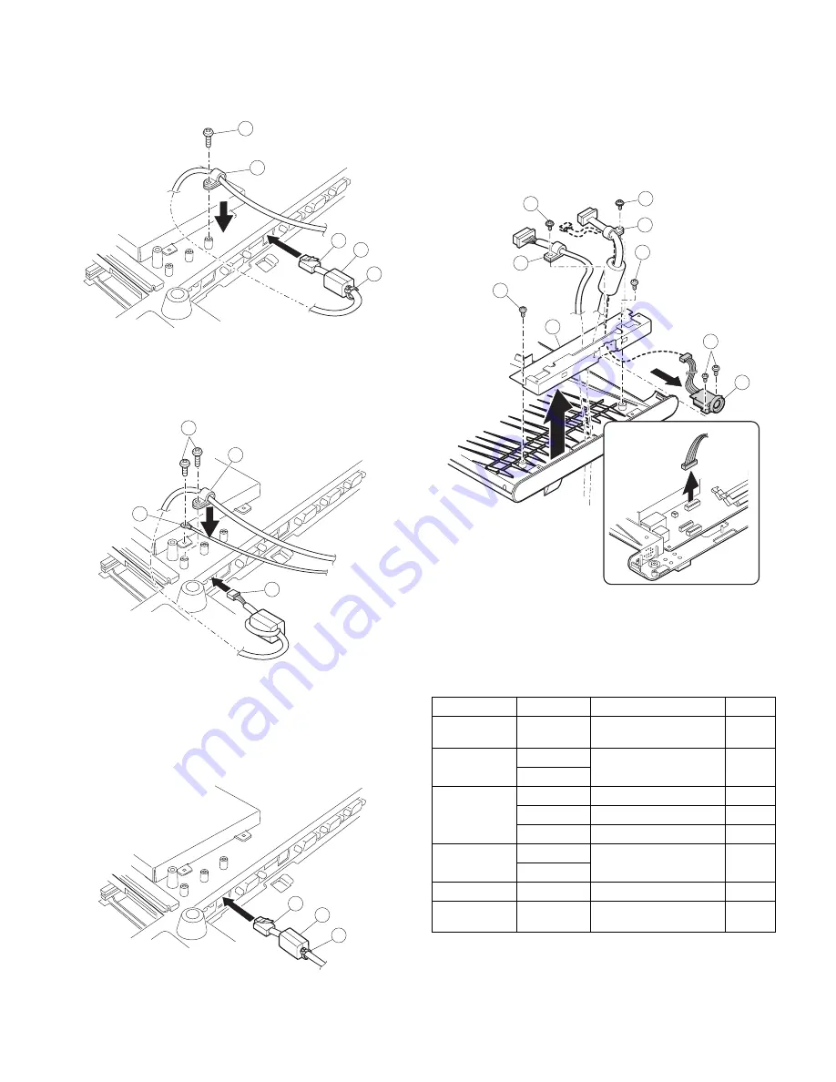
9-2. Fixing the pole display (UP-P20DP/DPB)

Fix the cable clamp 

2

 with the screw 

1

, and attach the

UP-P20DP cable 

3

.

Caution: Parts 

1

,

 2

,

 4

5

 are packed together with the set.

9-3. Fixing the drawer unit (ER-03DW/04DW/05DW)

Fix the cable clamp 

2

 and earth wire 

3

 with the screw 

1

,

and attach the drawer cable 

4

.

Caution: Parts 

1

2

 are packed together with the drawer as accessories.

9-4. Fixing the LAN cable

Fix each cable 

2

 with each screw 

1

, and connect the LAN

cable 

3

.

Caution: Parts 

2

,

 3

 are packed together with the set.

10. Removing the contactless clerk key

1.

Remove the screw 

1

, and remove the wire holder 

2

.

2.

Remove the screw 

3

, and remove the wire holder 

4

.

3.

Remove two screws 

5

, and disassemble the hinge angle

6

.

4.

Fixing the contactless clerk key unit 

8

, with the screw 

7

.

11. Specification

Options <UP-X500V>

1

2

3

4

5

1

2

3

4

1

3

2

Item

Model Name

Specification

Note

Customer
Display

UP-I20DP

2 line 20 digits dot display
Mounted in the cabinet

Customer Pole
display

UP-P20DP

2 line 20 digits dot display
External pole display

UP-P20DPB

Remote Drawer ER-03DW

ER-04DW

ER-05DW

Receipt &
Journal Printer

ER-01PU

2 station (Receipt/Journal)
printer

ER-01PUG

Hand Scanner

ER-A6HS1

for reading barcode

Contactless
clerk key

UP-R10CL

10 keys set

1

2

3

4

5

5

6

7

8

Summary of Contents for UP-X500

Page 1: ...nge without notice UPX500VIME POS TERMINAL MODEL UP X500 V version 1 Removing the rear cover unit 1 2 Removing the side cover 1 3 Removing the LCD unit 1 4 Removing the MCR unit 2 5 Fixing the HDD unit 2 6 Removing the AC cord 3 7 Removing the AC adapter 3 8 Removing the Main board Extention RAM module 3 9 COM port connector 4 9 1 FIXING THE REAR DISPLAY UP I20DP 4 9 2 FIXING THE POLE DISPLAY UP P...

Page 2: ... REGULATIONS BATTERY DISPOSAL THIS PRODUCT CONTAINS LITHIUM BATTERY THIS BATTERY MUST BE DISPOSED OF PROPERLY REMOVE THE BATTERY FROM THE PRODUCT AND CONTACT FEDERAL OR STATE ENVIRONMENTAL AGENCIES FOR INFORMATION ON RECYCLING AND DISPOSAL OPTIONS TRAITEMENT DES ACCUMULATEUR USAGÉS CE PRODUIT CONTIENT UN ACCUMULATEUR À LITHIUM CET ACCUMULATEUR USAGÉ DOIT ÊTRE TRAITÉ CORRECTEMENT ENLEVEZ L ACCUMULA...

Page 3: ...older 4 3 Remove the core 5 of the T P cable 4 Remove four screws 6 and disassemble the top cover unit 7 Precautions Before installation be sure to turn off the power Use gloves to protect your hands from being cut by the angle and the chassis Connect all the cables securely When connecting or disconnecting the cables be careful not to apply stress to the cables It may cause disconnection Ground t...

Page 4: ...e screw 5 and disassemble the Clamp 6 3 4 Removing the LCD unit 1 Remove six screws 1 and remove the touch panel 2 the inserter cable 3 and the LED cable 4 and disassemble the LCD assembly 2 Remove four screws 5 and disassemble the LCD unit 7 from the LCD plate 6 Caution Tighten the screw 1 at 3 5kg 3 5 Removing the touch panel Remove the T P angle A 2 T P angle B 3 with screws 1 And disassemble t...

Page 5: ...ct the connector 5 and install the HDD unit 3 with the screw 4 Caution The screw 4 is packed with the set as an accessory 6 Removing the AC cord Remove the screw 1 and remove the AC cord cover 2 Remove the screws 3 and remove the AC cover 4 Disconnect the connector and remove the earth cable 5 and the AC cord Caution Disconnect the power plug from the power outlet before work 7 Removing the AC ada...

Page 6: ...ion When installing or removing the memory be careful not to bring the memory module into contact with the CPU angle and the CPU fan 9 COM port connector 9 1 Fixing the rear display UP I20DP 9 1 1 Replace the UP I20DP sheet metal with a new one 9 1 2 Remove the display sheet 1 and install the UP I20DP 3 with the screw 2 9 1 3 Wind the UP I20DP harness one turn around the rib 1 insert the connector...

Page 7: ...ith the set 10 Removing the contactless clerk key 1 Remove the screw 1 and remove the wire holder 2 2 Remove the screw 3 and remove the wire holder 4 3 Remove two screws 5 and disassemble the hinge angle6 4 Fixing the contactless clerk key unit 8 with the screw 7 11 Specification Options UP X500V 1 2 3 4 5 1 2 3 4 1 3 2 Item Model Name Specification Note Customer Display UP I20DP 2 line 20 digits ...

Page 8: ...04 January Printed in Japan t COPYRIGHT 2004 BY SHARP CORPORATION All rights reserved Printed in Japan No part of this publication may be reproduced stored in a retrieval system or transmitted In any form or by any means electronic mechanical photocopying recording or otherwise without prior written permission of the publisher ...

Reviews: