background image

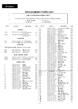
PART NO.

DESCRIPTION

CODE

206


A A

207


A


A

208

A A

209


A


A

210


A


A

211

  W a s h e r

A A

212

 Stop Washer

A A

214


  A   A

215

Stop Ring

A A

216

Stop Ring

A A

217

  S t o p   R i n g

A A

218

A A

219


A


A

220


  A   A

ACCESSORIES/PACKING PARTS

PWB-A

Packing Add. Front

A G

Packing Add. Rear

A G

Turntable Pad

A G

Packing Case

A M

 Cushion Mat

A B

 19 

1040 

Polyethylen 

 A A

Manual

 100 0

Polyethylen 

A C

P.W.B. ASSEMBLY 

(Not Replacement 

Main

Summary of Contents for RP-LGOOA

Page 1: ...set should be restored to Its original condition and only parts identical to those specified be used I INDEX TO CONTENTS Page SPEClFlCATlONS 2 NAMES OF PARTS DISASSEMBLY 2 ADJUSTMENT SCHEMATIC DIAGRAM WIRING SIDE OF P W BOARD EXPLODED VIEW REPLACEMENT PARTS LIST 6 7 SHARP CORPORATION ...

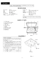
Page 2: ... Cartridge 9 Record Speed Selector 10 Record Size Selector 11 Play Button 4 12 Stop Button q Specifications for this model are subject to change without prior notice OF PARTS 1 2 3 4 s DISASSEMBLY lb 1 1 Figure 2 1 Caution on Disassembly Follow the below mentioned notes when disassembling the unit and reassembling it to keep its safety and excellent performance 1 Take Record out of the unit 2 Befo...

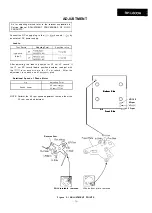
Page 3: ... if the 17 cm EP record lead in position deviates readjust with the revels arm excentrc pin for 17 cm record After the adjustment lock each one of excentric pins Rotational Speed of Phono Motor Jig Strobo viewer Adjusting Point 45 rpm VR102 33 rpm VRl 01 NOTE Perform the 45 rpm speed adjustment first and them the 33 rpm speed adjustment Reverse Arm 0 0 co co Bottom Side Bottom Side cl cl L L L J L...

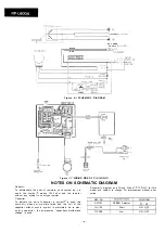
Page 4: ...as K is used the symbol K means 1000 ohm and the resistor without any symbol is ohm type resistor Capacitor To indicate the unit of capacitor a symbol P is used this symbol P means micro micro farad and the unit of the capacitor without such a symbol is microfarad As to elec trolytic capacitor the expression capacitance withstand voltage is used Schematic diagram and Wiring Side of P W Board for t...

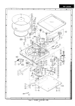
Page 5: ...I t t 1 I 2 I 3 I 4 I 5 I 6 Figure 5 CABINET EXPLODED VIEW 5 ...

Page 6: ...ver 26 99H25101337010 Spring Sensor Arm 27 99HD49519000 Plate Tonearm 28 99HD49521000 Plate Tonearm Driver 29 99HE49540000 Spring Tonearm Driver 30 99HC49517000 Sensor Arm 31 99HD49220000 Switch Plate 32 99HB49320000 Cam 33 99H24459398000 Rubber Cushion 34 99H25739077000 Support 35 99H27419987000 LeverStart 36 99H27439495000 Return Arm 37 99H27439497000 Trigger Arm 38 99H27439498000 Lead In Arm 39...

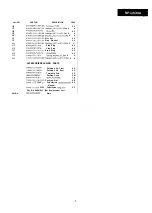
Page 7: ...ing A A 216 99HSCRET30SE Stop Ring A A 217 99H24220105020 Stop Ring A A 218 99HSN2H2N26SE Nut d2 6mm A A 219 99HSVS2L26SE Spring Washer 2 6mm A A 220 99HF266R50R5SE Washer 2 6 46 5X0 5mm A A ACCESSORIES PACKING PARTS PWB A 99HD21125000 Packing Add Front A G 99HD21126000 Packing Add Rear A G 99HD49706000 Turntable Pad A G 99HH32249040 Packing Case A M 99H49679000 Sheet Turntable AB 99H62519164900 C...

Page 8: ...S H A R F 1 A8807 805NS t IS J j Writer and Editor Quality Reliability Control Center of Audio Systems Group Sharp Corp Printed in Japan SA ...

Reviews: