
7
R-318BK
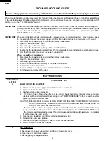
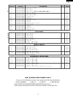
4. If the display fails to clear when the STOP/CLEAR pad is depressed, first verify the flat ribbon cable
is making good contact, verify that the door sensing switch (stop switch) operates properly; that is the
contacts are closed when the door is closed and open when the door is open. If the door sensing
switch (stop switch) is good, disconnect the flat ribbon cable that connects the key unit to the control
unit and make sure the door sensing switch is closed (either close the door or short the door sensing
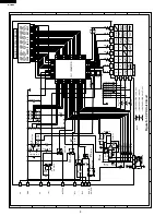
switch connecter). Use the Key unit matrix indicated on the control panel schematic and place a
jumper wire between the pins that correspond to the STOP/CLEAR pad making momentary contact.
If the control unit responds by clearing with a beep the key unit is faulty and must be replaced. If the
control unit does not respond, it is faulty and must be replaced. If a specific pad does not respond,
the above method may be used (after
clearing the control unit) to determine if
the control unit or key pad is at fault.
5. Reconnect all leads removed from
components during testing.
6. Re-install the outer case (cabinet).
7. Reconnect the power supply cord after
the outer case is installed.
8. Run the oven and check all functions.
5
4
3
2
1
0
9
8
7
6
STOP
CLEAR
AUTO
START
CLOCK
Chicken
breast
KITCHEN
TIMER
Fresh
Vegetables
Fish /
seafood
Ground meat
Ground meat
COMPU
DEFROST
Chicken
pieces
Popcorn
Reheat
START
POWER
LEVEL
MINUTE
PLUS
Fresh
roll /
muffin
Frozen
roll /
muffin
Frozen
entrees
Baked
potato
Steaks /
chops
INSTANT
ACTION
G 8
G 9
G10
G11
G12
G 7
G 6
G 5
G 4
G 3
G 2
G 1
6
4
5
1
2
3
6
4
5
1
2
3
A
B
C
D
E
F
G
H
A
B
C
D
E
F
G
H
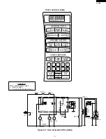
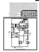
Figure S-2. Power Unit Circuit
+
–
+
–
+
–
A 1
A 2
C 1
C 2
C 3
C 4
C 5
C 6
C 7
C 8
C 9
SH-B
SH-A
T1
AC
AC
AC
MICRO
VA
GND
VC
INT
BUZZER
MICRO
DOOR
SWITCH
NOTE
: IF NOT SPECIFIED, 1/4w
±
5%
: IF NOT SPECIFIED, 1SS270A
TURNTABLE
MOTOR
OVEN LAMP
FAN
MOTOR
TURNTABLE
MOTOR
OVEN LAMP
FAN
MOTOR
WH-1
R4 27
R5 4.7k
R2 680 1/2w
R6 3.3k
SP1
VRS1
C1 0.1
µ
/50v
C3 0.1
µ
/50v
ZD1
HZ16-1
C4 10
µ
/35v
C5
10
µ
/35v
R3 510
1/2w
C2 1000
µ
/35v
R1 2.4k
(J1)
D5
D3
D4
D2
D1
a
c
d
b
D6
RY1
D7
D8
RY2
Q2 2SB1238
2SB1238
Q1
D1-D4
11ES1
Q3 DTD143ES
V
R
V
R
V
R
V
A
LD1-LD5
LD1 LD2 LD3 LD4 LD5
N.O.
N.O.
COM
COM
1
4
3
6