background image

20

E

Basic Operation

n

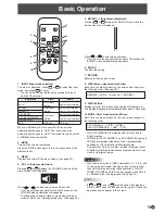
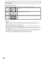
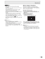
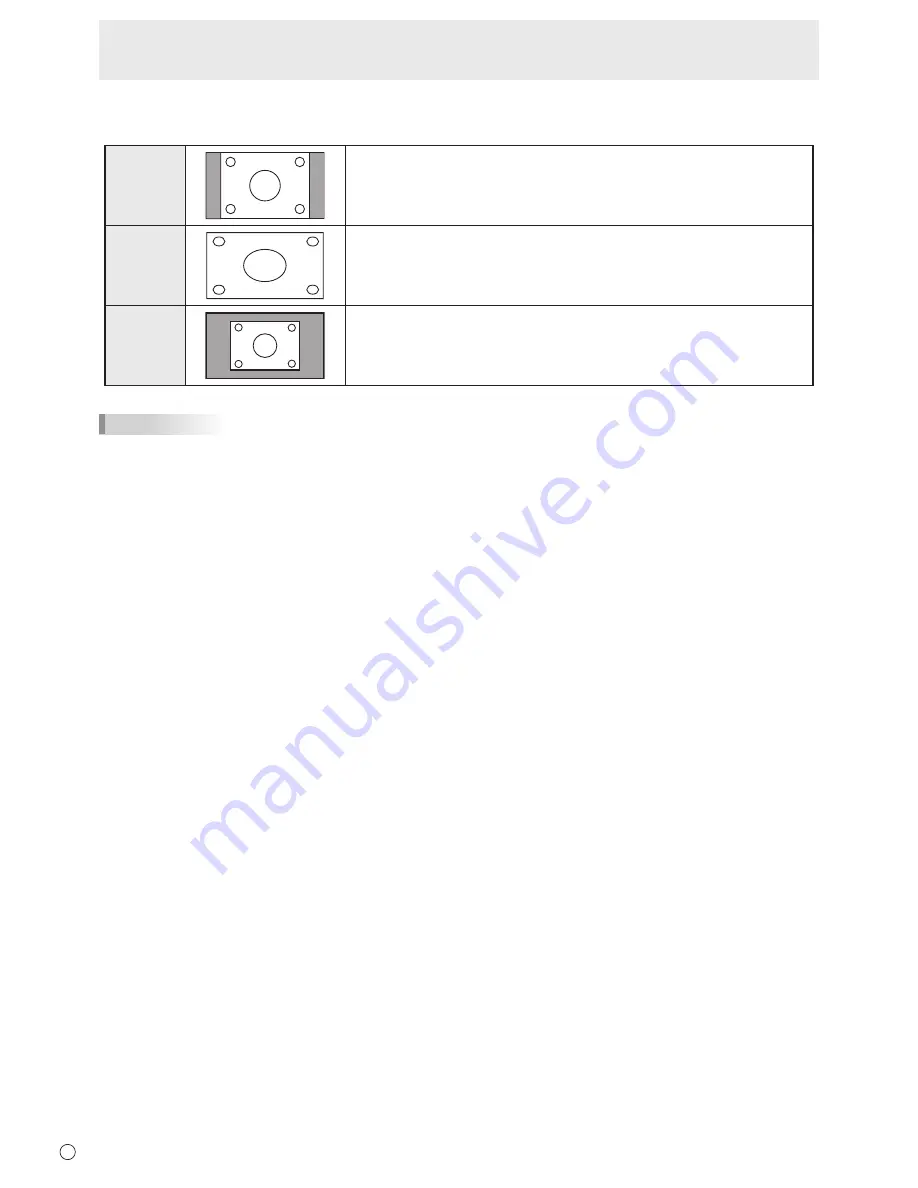
Switching the screen size

Even when the screen size is changed, the display may remain the same depending on the input signal.

NORMAL

Displays image so it fills the screen without changing the aspect ratio of the input 

signals.

WIDE

Displays image so it fills the entire screen.

Dot by Dot

Displays the dots of the input signals as the corresponding dots on the screen.

TIPS

•  Using this monitor’s screen-size switching to compress or expand the screen for commercial or public viewing in 

establishments like cafes or hotels may infringe on the rights of the creators, as protected by Copyright Law, so please be 

careful.

•  When “Enlarge” is set, the screen size is fixed to WIDE mode.

•  The appearance of the original video may change if you select a screen size with a different aspect ratio than the original 

image (e.g. TV broadcast or video input from external equipment). 

•  When an ordinary non-wide image (4:3) is viewed with the whole screen using the screen-size switching function of this 

monitor, the edge of the image may be lost or appear distorted. If you wish to respect the creator’s intentions, set the screen 

size to NORMAL.

•  When playing commercial software, parts of the image (like subtitles) may be cropped. In this case select the optimal screen 

size using the screen-size switching function of this monitor. With some software, there may be noise or distortion at the 

edges of the screen. This is due to the characteristics of the software, and is not a malfunction.

•  Depending on the original image size, black bands may remain at the edges of the screen.

Summary of Contents for PN-Y425

Page 1: ...PN Y555 PN Y475 PN Y425 LCD MONITOR OPERATION MANUAL ...

Page 2: ... dealer and ask for the correct method of disposal ONLY FOR USERS IN THE EUROPEAN UNION AND SOME OTHER COUNTRIES FOR INSTANCE NORWAY AND SWITZERLAND Your participation in separate collection is requested by law The symbol shown above appears on electrical and electronic equipment and batteries or the packaging to remind users of this If Hg or Pb appears below the symbol this means that the battery...

Page 3: ... literature accompanying the product FOR CUSTOMERS IN U K IMPORTANT The wires in this mains lead are coloured in accordance with the following code GREEN AND YELLOW Earth BLUE Neutral BROWN Live As the colours of the wires in the mains lead of this apparatus may not correspond with the coloured markings identifying the terminals in your plug proceed as follows The wire which is coloured GREEN AND ...

Page 4: ... or objects from resting on them 10 The LCD panel used in this product is made of glass Therefore it can break when the product is dropped or applied with impact Be careful not to be injured by broken glass pieces in case the LCD panel breaks 11 Overloading Do not overload AC outlets or extension cords Overloading can cause fire or electric shock 12 Entering of objects and liquids Never insert an ...

Page 5: ...is product may cause radio interference in which case the user may be required to take adequate measures 2 Batteries shall not be exposed to excessive heat such as sunshine fire or the like 3 To prevent injury this apparatus must be securely attached to the floor wall in accordance with the installation instructions 4 An apparatus with CLASS I construction shall be connected to a MAIN socket outle...

Page 6: ...6 E SAFETY PRECAUTIONS Continued WARNING To prevent the spread of fire keep candles or other open flames away from this product at all times ...

Page 7: ...may lead to excessive heat outbreak of fire or malfunction Please request a cleaning of the inside of the monitor from an authorized SHARP servicing dealer or service center Images cannot be rotated on this monitor When using in portrait orientation you will need to prepare appropriately orientated content in advance The AC outlet shall be installed near the equipment and shall be easily accessibl...

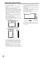
Page 8: ... monitor in landscape orientation Unit inch mm 5 16 7 5 16 7 7 7 8 200 2 50 Power LED If it is difficult to provide sufficient space for any reason such as the installation of the monitor inside a housing or if the ambient temperature may be outside of the range of 32 F 0 C to 104 F 40 C install a fan or take other measures to keep the ambient temperature within the required range Do not block any...

Page 9: ...ECAUTIONS 4 TIPS AND SAFETY INSTRUCTIONS 7 MOUNTING PRECAUTIONS 8 Supplied Components 9 Part Names 10 Connecting Peripheral Equipment 12 Connecting the Power Cord 14 Binding Cables 14 Setting the USB flash drive cover 15 Affixing the Stand Hole Protection Covers 15 Preparing the Remote Control Unit 16 Installing the batteries 16 Remote control operation range 16 Turning Power On Off 17 Turning on ...

Page 10: ...USB flash drive cover See page 15 7 Vents 8 Speakers 9 AC input terminal See page 14 10 Main power switch See page 17 11 HDMI input terminal See page 12 12 DVI D input terminal See page 12 13 DVI D output terminal See page 13 14 LAN terminal See page 13 15 D sub input terminal See page 12 16 USB port See page 12 17 RS 232C input terminal See page 13 18 RS 232C output terminal See page 13 19 Audio1...

Page 11: ... 3 MUTE button See page 19 4 VOL buttons See page 19 BRIGHT buttons See page 19 Cursor control buttons 5 DISPLAY Red button See page 19 6 MODE Green button See page 19 7 INPUT button See page 19 8 MENU button See page 19 9 ENTER button See page 19 10 RETURN button See page 19 11 SIZE Yellow button See page 19 ...

Page 12: ...onitor s audio output to the speakers or other devices The audio input terminals used in each input mode are factory set as follows Input mode Audio input terminal DVI D Audio1 input terminal HDMI PC HDMI AV HDMI input terminal Audio1 input terminal D SUB RGB Audio1 input terminal D SUB COMPONENT D SUB VIDEO Audio2 input terminals USB USB port 1 HDMI input terminal Use a commercially available HDM...

Page 13: ... image quality When the input mode is set to a mode other than DVI D video cannot be output 8 Audio output terminals The output sound varies depending on the input mode It is not possible to control the sound output from the audio output terminals with the AUDIO menu Set this function with AUDIO OPTION in the SETUP menu See page 27 9 RS 232C input terminal 10 RS 232C output terminal You can contro...

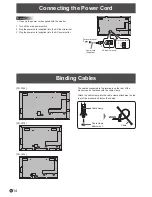
Page 14: ...rd supplied into the AC power outlet Main power switch 1 AC input terminal Power cord Supplied For power outlet 2 3 Binding Cables The cables connected to the terminals on the rear of the monitor can be fastened with the cable clamp Attach the cable clamp into the cable clamp attachment on the rear of the monitor and fasten the cables PN Y555 PN Y475 PN Y425 Cable clamp attachment Cable Cable clam...

Page 15: ...over and secure with the provided screw USB flash drive cover screw TIPS If the USB flash drive will be attached use a USB flash drive with dimensions no greater than 1 15 16 inch 50 mm L 13 16 inch 20 mm W 1 2 inch 12 mm H After installing the monitor affix the stand hole protection covers as necessary 1 Peel off the backing sheet and affix the cover on the monitor ...

Page 16: ...x 16 4 feet 5 m at an angle of approx 10 from the center to the top bottom right left of the remote control sensor Remote control sensor 16 4 feet 5 m 10 10 10 10 TIPS Do not expose the remote control unit to shock by dropping or stepping on it This could lead to a malfunction Do not expose the remote control unit to liquids and do not place it in an area with high humidity The remote control unit...

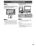
Page 17: ... For a complete electrical disconnection pull out the main plug Turning Power On Off Turning power on off Press the POWER button to turn the power ON OFF POWER button Power LED Status Status of the monitor Green lit Power on Orange lit Power off Standby mode Green flashing Input signal waiting mode Caution When switching the main power switch or the POWER button off and back on always wait for at ...

Page 18: ...y mode is also minimized MODE2 Will perform standard operation OFF IF NO OPERATION is set to OFF and STANDBY MODE is set to STANDARD These settings can be changed Even after being set changes can be made using OPERATION MODE located in the menu of the monitor See page 27 nDate time setting If the time has not been set such as when the monitor is first turned on set the date and time in DATE TIME S...

Page 19: ...u when the menu screen is not displayed 31 Press or to adjust the brightness If you do not press any buttons for about 30 seconds the BRIGHT menu automatically disappears 6 ENTER Confirms the setting 7 RETURN Returns to the previous screen 8 SIZE Screen size selection Yellow Each time you press this button the screen size changes in the following order See page 20 NORMAL WIDE Dot by Dot NORMAL 9 D...

Page 20: ...to WIDE mode The appearance of the original video may change if you select a screen size with a different aspect ratio than the original image e g TV broadcast or video input from external equipment When an ordinary non wide image 4 3 is viewed with the whole screen using the screen size switching function of this monitor the edge of the image may be lost or appear distorted If you wish to respect...

Page 21: ...ectly set and if AUTO PLAY is not correctly set in the monitor settings menu n To stop auto play 1 Press INPUT Playing files You can play the specified image video audio files in a USB flash drive 1 Insert the USB flash drive into a USB port on the monitor See page 12 2 Change an input mode to USB See page 19 3 Select the files to be played and the play method See page 22 n Supported formats The t...

Page 22: ...tion year 3 Movie Select a file with or 4 Music Select a file with or To move to the file genre menu press To narrow down audio files select with or and press ENTER To change the group of a file press MODE Green with the file selected Select one of the items below with or and press ENTER Album Group by album Artist Group by artist Genre Group by genre Track Group by first letter of song title A st...

Page 23: ... music file and pause You can also mute the sound with MUTE If RETURN is pressed while the music is paused playback will end TIPS To adjust the sound volume for video files and audio files follow the procedure described in Settings during play See page 24 If the next operation is performed during processing of an operation that involves a high processing load such as Move forward about 10 seconds ...

Page 24: ...es the screen size of video Eco settings Screen off Use this during playback of a video or music to turn off the screen and play only the music The audio of a video or music does not turn off To show the screen press ENTER on the remote control Clock Only when playing video or music Clock A clock can be displayed in the upper right corner of the screen The clock constantly appears during file play...

Page 25: ...lay the menu screen SCREEN PICTURE AUDIO SETUP H V POS SIZE RESET 2 Press or to select PICTURE and press ENTER 3 Press or to select CONTRAST and press ENTER SCREEN PICTURE AUDIO SETUP BRIGHT CONTRAST BLACK LEVEL TINT COLORS COLOR ADJUSTMENT RESET 50 4 Press or to adjust the setting and press ENTER SCREEN PICTURE AUDIO SETUP BRIGHT CONTRAST BLACK LEVEL TINT COLORS COLOR ADJUSTMENT RESET 60 5 Press ...

Page 26: ...olor towards magenta and selecting changes it towards green COLORS Adjusts the color intensity SHARPNESS HDMI AV D SUB COMPONENT D SUB VIDEO Adjusts the sharpness of the image COLOR ADJUSTMENT COLOR MODE Changes the color mode on the screen The color mode on the screen can also be changed using a remote control unit See page 19 sRGB is DVI D HDMI PC D SUB RGB input only See page 19 for details WHI...

Page 27: ...settings to control the monitor from the computer via LAN See page 38 ID SETTING Assigns ID numbers to monitors connected in a daisy chain see page 33 using the RS 232 cables The numbers 0 to 25 are available for ID numbers If 0 is set the system regards this as the state where no ID number is set MULTI ENLARGE See page 29 Sets whether or not to use the enlarge function ADVANCED ENLARGE ENLARGE H ...

Page 28: ...ected equipment When there are no signals at any of the input terminals switching is continued until an input signal is detected and the monitor does not enter signal standby mode SCAN MODE HDMI AV Sets the scan mode ADJUSTMENT LOCK You can disable operations on the monitor and the remote control unit that use buttons MONITOR BUTTONS UNLOCKED Enables operation LOCK ALL No operations are possible L...

Page 29: ... in the vertical direction in ENLARGE V 5 Set the section of the separated image to be displayed on each monitor in ENLARGE POS 1 Press ENTER 2 Press or to select position then press MENU Enlarge You can align 4 9 16 or 25 monitors and integrate them into a single large screen to display Enlarged views of separated images are displayed in each monitor 3 1 4 2 2 4 1 3 4 monitors 4 monitors 1 2 3 5 ...

Page 30: ...me playlist Audio files cannot be used 1 Select the type of file to be set in the list with or and press ENTER A list of folders or files of the selected type Photo Video appears 2 Select a file with or and press ENTER to set the file When a file is selected and set it appears in the left area When you select a file in the left area and press ENTER it disappears from the left area To move up a fol...

Page 31: ...t has a small number has precedence over that of a large number when schedules overlap The play list is saved in usb_schedulinglist txt in the USB flash drive nScreen display for adjustment Before making adjustments in the SCREEN menu or PICTURE menu display an image to brighten the entire screen If you are using a Windows PC use the adjustment pattern on the supplied CD ROM Opening the adjustment...

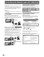
Page 32: ... the length of the cable used and the surrounding environment RS 232C input terminal RS 232C output terminal To COM port PC First monitor Second monitor RS 232 straight cables commercially available Communication conditions Set the RS 232C communication settings on the PC to match the monitor s communication settings as follows Baud rate 9600bps Stop bit 1 bit Data length 8 bits Flow control None ...

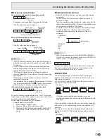
Page 33: ...the following commands is used RSET INPS ASNC WIDE POWR EMHV EPHV ESHV ENLG nCommunication interval After OK or ERR is returned you must send the following commands To set a timeout for the command response specify 10 seconds or longer When connecting multiple monitors in a daisy chain set the timeout to at least the product of the monitor s position from the computer multiplied by 10 seconds Exam...

Page 34: ...xt command is for the monitor with ID number 2 WAIT Searching for monitor with ID number 2 OK 002 Found monitor with ID number 2 VOLM0030 Sets volume of monitor with ID number 2 to 30 WAIT Processing OK 002 OK response from monitor with ID number 2 VOLM0020 Sets volume to 20 OK 001 The volume of the monitor with ID number 1 the one directly connected to the PC is set to 20 The IDSL command is effe...

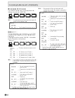
Page 35: ...l the connected monitors If you want to determine that a value has been returned by a specific set assign ID numbers to each monitor in advance When some monitors do not return their responses the probable cause is that the monitors could not receive the command or command processing is not complete Do not send a new command Example When 4 monitors are connected and assigned ID numbers 1 through 4...

Page 36: ...y mode R 0 Standby mode 1 Normal mode 2 Input signal waiting mode INPUT MODE SELECTION INPS W 0 Toggle change for input mode 1 DVI D 2 D SUB RGB 3 D SUB COMPONENT 4 D SUB VIDEO 9 HDMI AV 10 HDMI PC 11 USB R 1 DVI D 2 D SUB RGB 3 D SUB COMPONENT 4 D SUB VIDEO 9 HDMI AV 10 HDMI PC 11 USB If power standby mode is entered when the input mode is USB the input terminal that was used prior to switching t...

Page 37: ... REMOTE CONTROL ALCR WR 0 3 0 3 0 UNLOCKED 1 LOCK ALL 2 LOCK EXCEPT VOLUME 3 LOCK EXCEPT POWER Others Function Command Direction Parameter Reply Control Response contents VOLUME VOLM WR 0 31 0 31 MUTE MUTE WR 0 1 0 1 0 OFF 1 ON INFORMATION MODEL INF1 R Value SERIAL NO SRNO R Value TEMPERATURE SENSOR DSTA R 0 Internal temperature normal 1 Internal temperature abnormal has occurred and the monitor i...

Page 38: ...o set on the monitor Set the LAN SETUP options See page 27 After setting each item press RETURN DHCP CLIENT If your LAN has a DHCP server and you wish to obtain an address automatically change this setting to ON To set the address manually set this to OFF IP ADDRESS If the DHCP CLIENT is set to OFF specify an IP address SUBNET MASK If the DHCP CLIENT is set to OFF specify the subnet mask DEFAULT G...

Page 39: ...d as response 2 Enter the user name and password The default settings are blank 2 Send commands to control the monitor The commands used are the same as those for RS 232C Refer to the communication procedure see page 32 for operation Usable commands are provided in the RS 232C command table see page 36 3 Disconnect the connection with the monitor and quit the function 1 Send BYE When the transmiss...

Page 40: ... on again If the monitors are connected in a daisy chain turn off the power to all the monitors connected in a daisy chain and then turn the power on again If an AV signal such as 1920 x 1080i 720 1440 x 576i or 720 1440 x 480i is displayed using the DVI D input display problems such as faint colors may occur Display using HDMI AV D SUB COMPONENT or D SUB VIDEO The video from D Sub input terminal ...

Page 41: ...e the cause of the excessive temperature rise If the monitor enters standby mode due to a rise in temperature to return to normal display turn the power switch off and then back on again The monitor however will enter standby mode again if the cause of the temperature rise is not eliminated See page 8 Check whether the monitor is placed at a location where a quick rise in temperature is likely Int...

Page 42: ...io RCA pin L R x 1 Serial RS 232C D sub 9 pin x 1 LAN terminal 10 BASE T 100 BASE TX Speaker output 7 W 7 W Power requirement AC 100 240 V 1 7 A 50 60 Hz AC 100 240 V 1 5 A 50 60 Hz AC 100 240 V 1 4 A 50 60 Hz Operating temperature 1 32 F to 104 F 0 C to 40 C Operating humidity 20 to 80 no condensation Power consumption Input signal waiting mode standby mode 2 150 W 16 W 16 W 135 W 16 W 16 W 120 W...

Page 43: ...200 15 3 4 400 VESA holes 7 7 8 200 7 7 8 200 15 3 4 400 VESA holes PN Y555 PN Y475 PN Y425 When mounting the monitor be sure to use a wall mount bracket that complies with the VESA compatible mounting method SHARP recommends using M6 screws and tighten the screws Note that screw hole depth of the monitor is 3 8 inch 10 mm Loose mounting may cause the product to fall resulting in serious personal ...

Page 44: ...M Screen Power consumption Monitor ON Display 150 W 135 W 120 W Active OFF No display 16 W 16 W 16 W Values of the PN Y555 PN Y475 and PN Y425 in that order from the top nDDC plug and play The monitor supports the VESA DDC Display Data Channel standard DDC is a signal standard for plug and play between monitors and computers Information about resolution and other parameters is exchanged between th...

Page 45: ... 79 5MHz 83 5MHz 108 0MHz 108 0MHz 135 0MHz 85 5MHz 121 75MHz 106 5MHz 162 0MHz 154 0MHz 74 4MHz 85 383MHz 148 5MHz 28 3MHz Yes Yes Yes Yes Yes Yes Yes Yes Yes Yes Yes Yes Yes Yes Yes Yes Yes Yes Yes Yes Yes Yes Yes Analog D SUB Yes Yes Yes Yes Yes Yes Yes Yes Yes Yes Yes Yes Yes Yes Yes Yes Yes Yes Yes Yes Yes Yes Yes Yes DVI D HDMI Yes Yes Yes Yes Yes Yes Yes Yes Yes Yes Yes Yes Yes Yes Yes Yes ...

Page 46: ...Green video signal input 10 GND 3 Blue video signal input 11 N C 4 N C 12 DDC data 5 N C 13 Hsync signal input 6 GND for red video signal 14 Vsync signal input 7 GND for green video signal 15 DDC clock 8 GND for blue video signal nHDMI input terminal pins HDMITM Connector No Function No Function 1 TMDS data 2 11 TMDS clock shield 2 TMDS data 2 shield 12 TMDS clock 3 TMDS data 2 13 CEC 4 TMDS data ...

Page 47: ... plug detection 5 N C 17 TMDS data 0 6 DDC clock 18 TMDS data 0 7 DDC data 19 TMDS data 0 5 shield 8 N C 20 N C 9 TMDS data 1 21 N C 10 TMDS data 1 22 TMDS clock shield 11 TMDS data 1 3 shield 23 TMDS clock 12 N C 24 TMDS clock nRS 232C output terminal pins D sub 9 pin No Function No Function 1 N C 6 N C 2 Received data 7 N C 3 Transmitted data 8 N C 4 N C 9 N C 5 GND ...

Page 48: ...st 4 times or more the weight of the monitor Install by the most suitable method for the material and the structure To attach a VESA compliant mounting bracket use M6 screws that are 5 16 inch 8 mm to 3 8 inch 10 mm longer than the thickness of the mounting bracket Do not use an impact driver When moving the monitor hold the parts marked by below Do not hold the LCD panel This may cause product da...

Page 49: ...PN Y555 Y475 Y425 Me EN14G 2 ...

Reviews: