background image

43

E

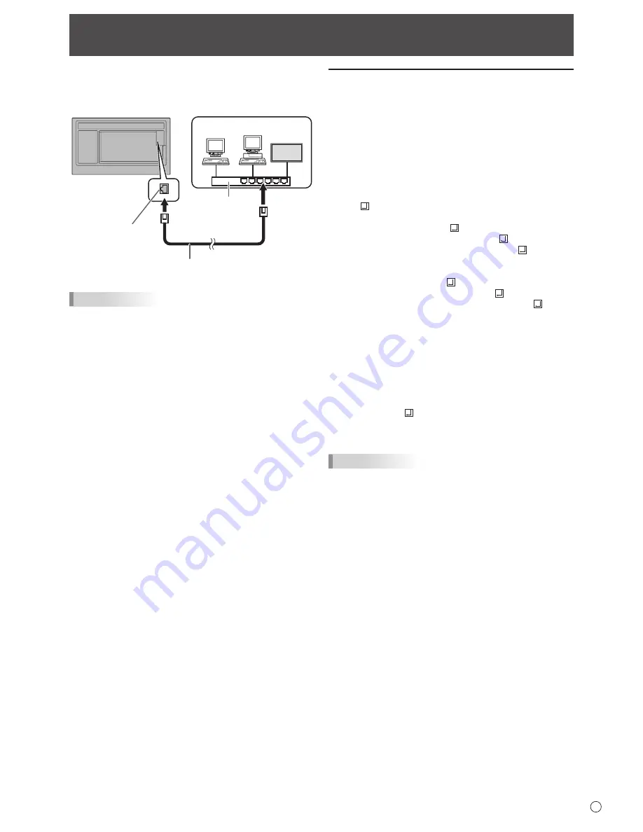
Your monitor can be connected to a LAN allowing you to 

control it from a computer on the LAN. 

The connection requires a commercially available LAN cable 

(UTP cable, Category 5, straight through).

Hub

Network (LAN)

LAN cable (commercially available, straight)

LAN terminal

TIPS

•  This monitor must be connected to a network.


Configure settings required for connection to a network in 

“System Settings” – “Ethernet” on the CONTENT MENU 

screen of APPLICATION mode.

•  When POWER SAVE MODE is set to ON, the control is 

disabled in the standby mode.

•   To control the monitor via LAN, set RS-232C/LAN SELECT 

to LAN. (See page 26.)

•  You cannot use RS-232C and LAN control simultaneously. 

Controlling the Monitor with a computer (LAN)

Command-based control

You can control the monitor using RS-232C commands 

(see page 39) via terminal software and other appropriate 

applications.

Read the manual for the terminal software for detailed 

instructions.

(1)  Connect the computer to the monitor.

1.  Specify the IP address and data port number (10008) 

and connect the computer to the monitor. 

When connection has been established successfully, 

[ Login:] is returned as response.

2.  Send the user name.

•  Send [user name] + [ ].

•  If the user name is not set, send [ ].

•  When the transmission is successful, [ Password:] 

is returned as response.

3.  Send the password.

•  Send [password] + [ ].

•  If the password is not set, send [ ].

•  When the transmission is successful, [OK  ] is 

returned as response.

(2)  Send commands to control the monitor.

•  The commands used are the same as those for RS-

232C. Refer to the communication procedure (see 

page 35) for operation.

•  Usable commands are provided in the RS-232C 

command table (see page 39).

(3)  Disconnect the connection with the monitor and 

quit the function.

1.  Send [QUIT ].


When the transmission is successful, [goodbye] is 

returned and the connection is disconnected.

TIPS

•  Connection is automatically disconnected when the 

time specified in AUTO LOGOUT TIME elapses over a 

no-communication period.

Summary of Contents for PN-B401

Page 1: ...PN B501 PN B401 LCD MONITOR OPERATION MANUAL ...

Page 2: ...ORTANT To aid reporting in case of loss or theft please record the product s model and serial numbers in the space provided The numbers are located in the rear of the product Model No Serial No U S A ONLY ...

Page 3: ...tions to this equipment not expressly approved by the manufacturer could void the user s authority to operate this equipment NOTE This equipment has been tested and found to comply with the limits for Class A digital device pursuant to Part 15 of the FCC Rules These limits are designed to provide reasonable protection against harmful interference when the equipment is operated in a commercial envi...

Page 4: ...eople from stepping on them or objects from resting on them 10 The LCD panel used in this product is made of glass Therefore it can break when the product is dropped or applied with impact Be careful not to be injured by broken glass pieces in case the LCD panel breaks 11 Overloading Do not overload power outlets or extension cords Overloading can cause fire or electric shock 12 Entering of object...

Page 5: ...user may be required to take adequate measures An apparatus with CLASS I construction shall be connected to a MAIN socket outlet with a protective earthing connection To maintain compliance with EMC regulations use shielded cables to connect to the following terminals HDMI input terminal D sub input terminal RS 232C input output terminals and DisplayPort input output terminals If a monitor is not ...

Page 6: ...prepare appropriately orientated content in advance The AC outlet shall be installed near the equipment and shall be easily accessible If you or a third party uses the product incorrectly or if the product is subjected to the effects of static electricity or electrical noise or if the product malfunctions or is repaired there is a risk that saved data will be corrupted or lost Always back up impor...

Page 7: ... temperature inside the monitor rises this could lead to a malfunction Do not place the monitor on a device which generates heat Adhere to the following when installing the monitor in its portrait orientation Failing to adhere to the following may cause malfunctions Install the monitor such that the power LED is located on the right side Set the PORTRAIT LANDSCAPE INSTALL in the MONITOR menu to PO...

Page 8: ...he manual for each Contents IMPORTANT INFORMATION 3 DEAR SHARP CUSTOMER 4 SAFETY PRECAUTIONS 4 TIPS AND SAFETY INSTRUCTIONS 6 MOUNTING PRECAUTIONS 7 Supplied Components 8 Part Names 9 Connecting Peripheral Equipment 11 Connecting the Power Cord 13 Binding Cables 13 Attaching the logo sticker 14 Attaching the USB flash drive SD card cover 14 Preparing the Remote Control Unit 15 Installing the batte...

Page 9: ...vided for possible future optional function expansion Offering of this terminal is not a guarantee that future expanded functionality will be released 12 RS 232C input terminal See page 12 13 Vents 14 Power LED See page 17 Remote control sensor See page 15 15 Power button See page 17 16 Input button See page 20 17 LAN terminal See page 12 18 USB port See page 12 19 SD card slot See page 12 20 Expa...

Page 10: ...10 E Part Names nRemote control unit 2 1 1 Signal transmitter 2 Operation buttons See pages 17 and 19 ...

Page 11: ...t terminal HDMI2 HDMI2 input terminal D SUB RGB D SUB COMPONENT Audio input terminal 1 DisplayPort output terminal The video of the current input mode can be output to an external device Use a commercially available DisplayPort cable Outputting HDCP encrypted video requires an external device which supports HDCP This terminal can be used to make a daisy chain connection by connecting these monitor...

Page 12: ... output terminal You can control the monitor from a computer by connecting a commercially available RS 232 straight cable between these terminals and the computer 10 SD card slot This is used in APPLICATION mode For details see the Software Guide 11 USB port This is used in APPLICATION mode For details see the Software Guide 12 LAN terminal You can control the monitor from a computer on a network ...

Page 13: ...into the power outlet Main power switch AC input terminal 1 2 For power outlet 3 Power cord Supplied Binding Cables The supplied cable clamps affixing type can be used to clamp the power code and cables connected to the back of the monitor Caution Attach the supplied cable clamps to a flat surface Do not attach over a vent Remove any dust or dirt before attaching Cable clamp affixing type Affixing...

Page 14: ...D card cover supplied to this monitor USB flash drive SD card cover supplied 2 Secure the cover using USB flash drive SD card cover fixing screw supplied USB flash drive SD card cover fixing screw supplied Attaching the USB flash drive SD card cover TIPS If the cover will be attached use a USB flash drive no larger than 2 3 4 inch 70 mm L excluding the terminal x 11 16 inch 17 mm W x 5 16 inch 8 m...

Page 15: ...ou will not be using the remote control for a long time remove the batteries Use manganese or alkaline batteries only Remote control operation range Remote control sensor in The remote control can be operated even when the remote control sensor is stored inside the monitor Point the remote control unit toward the remote control sensor on the bottom of the monitor or the right side of the monitor i...

Page 16: ... could lead to a malfunction Do not expose the remote control unit to liquids and do not place it in an area with high humidity The remote control unit may not work properly if the remote control sensor is under direct sunlight or strong lighting Objects between the remote control unit and the remote control sensor may prevent proper operation Replace the batteries when they run low as this may sh...

Page 17: ...urning power on off Press the POWER button to turn the power ON OFF You can also turn the power ON OFF by pressing the MONITOR ON button MONITOR OFF button on the remote control unit Power button Power LED Status Status of the monitor Green lit Power on Orange lit Power off Standby mode Green flashing Input signal waiting mode TIPS When the main power switch is off the monitor cannot be turned on ...

Page 18: ...he date in Month Day Year order The clock is maintained by the internal battery If you already set the time but the date time setting screen appears when the power is turned on the internal battery may be exhausted After replacing the internal battery set the date and time as explained in step 1 on the left Please contact an authorized SHARP servicing dealer or service center for assistance with i...

Page 19: ...monitor information INPUT MODE SIZE COLOR MODE BRIGHT VOLUME ID No REMOTE No MODEL VERSION ANDROID VERSION KERNEL VERSION BUILD No S N STATUS INFORMATION1 1 9 2 0 x 1 0 8 0 V 60 Hz H 67 5 kHz D SUB RGB WIDE STD 31 15 0 0 PN B501 0000 000000 00 0000 01 01 2017 SUN 12 00 AM END RETURN LAN RS 232C LAN SELECT DHCP CLIENT IP ADDRESS SUBNET MASK DEFAULT GATEWAY MONITOR NAME DATA PORT MAC ADDRESS INFORMA...

Page 20: ...d applications For details of APPLICATION mode see the Software Guide You can change the input mode by pressing the INPUT button of the monitor Input mode Video Audio APPLICATION 1 APPLICATION APPLICATION DisplayPort DisplayPort input terminal 4 HDMI1 HDMI1 input terminal HDMI2 HDMI2 input terminal D SUB RGB D sub input terminal 3 Audio input terminal D SUB COMPONENT OPTION 2 Expansion slot 4 1 Wh...

Page 21: ... be careful When Enlarge is set the screen size is fixed to WIDE mode When dual screen display is selected the screen size cannot be changed The appearance of the original video may change if you select a screen size with a different aspect ratio than the original image e g TV broadcast or video input from external equipment When 4 3 video is viewed with the whole screen using the screen size swit...

Page 22: ...30 12 SCREEN PICTURE SETUP MONITOR MULTI PIP OTHERS PICTURE BACK RETURN 1 9 2 0 x 1 0 8 0 V 60 Hz H 67 5 kHz D SUB RGB 4 Press the or button to adjust the setting BRIGHT CONTRAST BLACK LEVEL TINT COLORS SHARPNESS COLOR ADJUSTMENT ADVANCED RESET 31 40 30 30 30 12 SCREEN PICTURE SETUP MONITOR MULTI PIP OTHERS PICTURE BACK RETURN 1 9 2 0 x 1 0 8 0 V 60 Hz H 67 5 kHz D SUB RGB For items that have pres...

Page 23: ... it Adjustments to PHASE should be made only after CLOCK has been correctly set H POS D SUB RGB Adjust the horizontal position of the image V POS D SUB RGB Adjust the vertical position of the image H SIZE D SUB RGB Adjust the horizontal size of the image V SIZE D SUB RGB Adjust the vertical size of the image RESOLUTION SETTING D SUB RGB H RESOLUTION Sets proper horizontal resolution when the resol...

Page 24: ...Selects the color temperature when the WHITE BALANCE is set to PRESET The setting values are shown for reference The color temperature of the screen varies over time This function is not intended to keep the color temperature constant USER Adjusts each item when the WHITE BALANCE is set to USER R CONTRAST Adjusts bright toned red component G CONTRAST Adjusts bright toned green component B CONTRAST...

Page 25: ... range cannot be set appropriately even when using AUTO set according to the image When the setting is different images will be displayed with washed out blacks and compressed gradients DISPLAY COLOR PATTERN Displays a color pattern Can be displayed while the menu screen is displayed so you can refer to the pattern while adjusting the image When WHITE RED GREEN or BLUE is displayed you can set the...

Page 26: ...just the volume from the speakers of this monitor and the audio output terminal simultaneously by using VOLUME VARIABLE2 You can adjust the volume from the audio output terminal by using VOLUME Sound will not be output from the speakers of this monitor AUDIO INPUT LEVEL Selects the maximum audio input level of the audio input terminal START INPUT MODE You can set the input mode that will be in eff...

Page 27: ...tain RS 232C commands and LAN control cannot be used in standby mode See pages 35 and 43 OFF IF NO OPERATION Determines whether or not to set the monitor to go into standby mode when there is no operation from the remote control unit or RS 232C commands When the setting is ON set the time until standby mode is entered in TIME POWER ON DELAY When ON is set you can delay the screen display after the...

Page 28: ... units will be displayed smoothly when a group of monitors are aligned in multiples to display a single image BEZEL TOP BEZEL BOTTOM BEZEL RIGHT BEZEL LEFT Sets the frame width of the display PIP PbyP PIP MODES Sets the display method OFF Displays one screen PIP Displays a sub screen inside a main screen PbyP Displays a main screen and a sub screen in a line PIP SIZE Sets the size of the sub scree...

Page 29: ...will not appear Input does not change automatically for terminals without a priority setting LOGO SCREEN Sets whether or not to display the logo screen SCAN MODE HDMI1 HDMI2 D SUB COMPONENT OPTION Sets the scan mode used for video input MODE1 Over scan display MODE2 Under scan display MODE3 Under scan display when the input signal is 1080i p Otherwise over scan display Even when MODE1 is selected ...

Page 30: ...Use the automatic screen adjustment Menu Items nDual screen display You can display two screens simultaneously Set this function with PIP MODES of PIP PbyP in the MULTI PIP menu PIP Main screen Sub screen A sub screen is displayed inside a main screen PbyP Main screen Sub screen A main screen and a sub screen are displayed in a line The currently selected input signal is displayed on the main scre...

Page 31: ...gh Friday is also possible 2 EVERY DAY Executes the SCHEDULE every day regardless of the day of the week 4 TIME Specifies the time to execute the SCHEDULE Set the time on a 12 hour basis Factory default Can be entered as 24 hour time using the TIME setting in DATE TIME FORMAT 5 INPUT Specifies the input mode at power on If you don t specify this the input active at the last power off will appear W...

Page 32: ...ored This is due to the specifications of the input signal and is not a malfunction nAbout remote control numbers If there is another monitor nearby you can change the remote control number to prevent the other monitor from being operated by the remote control unit Set the same number in the monitor and in the remote control unit TIPS You can set remote control numbers to values from 0 to 9 When t...

Page 33: ...UNCTION ON 2 Only the FUNCTION operation is enabled Disables all operations other than FUNCTION not even power on off ADJUSTMENT LOCK TARGET Sets the target to prohibit operation of with ADJUSTMENT LOCK REMOTE CONTROL Prohibits remote control operation MONITOR BUTTONS Prohibits monitor button operation BOTH Prohibits remote control and monitor button operation OSD DISPLAY Shows hides the menu mode...

Page 34: ...s monitor SAVE Save the settings to a USB flash drive If settings are already saved in the USB flash drive the settings will be overwritten RESTORE Restore the settings saved in a USB flash drive to this monitor APPLICATION REBOOT When SET is selected the Android system of APPLICATION mode restarts MAIN SOFTWARE UPDATE Not normally used Used by service technicians when performing repairs or otherw...

Page 35: ...nal RS 232C input terminal Communication conditions Set the RS 232C communication settings on the computer to match the monitor s communication settings as follows Baud rate Stop bit 1 bit Data length 8 bits Flow control None Parity bit None Set to the same baud rate as the BAUD RATE setting of SETUP menu Initial setting 38400 bps When connecting multiple monitors in a daisy chain set all monitors...

Page 36: ...2C LAN SELECT is set to LAN U N S E L E C T E D Return code 0DH 0AH nCommunication interval After OK or ERR is returned you must send the following commands To set a timeout for the command response specify 10 seconds or longer When connecting multiple monitors in a daisy chain set the timeout to at least the product of the monitor s position from the computer multiplied by 10 seconds Example 3rd ...

Page 37: ...with ID number 2 VOLM0020 Sets volume to 20 OK 001 The volume of the monitor with ID number 1 the one directly connected to the computer is set to 20 The IDSL command is effective only once for the immediately succeeding command IDLK The parameter of this command sets the ID number of the monitor The monitor is subject to all subsequent commands Example IDLK0002 Following commands are for the moni...

Page 38: ...by all the connected monitors If you want to determine that a value has been returned by a specific set assign ID numbers to each monitor in advance When some monitors do not return their responses the probable cause is that the monitors could not receive the command or command processing is not complete Do not send a new command Example When 4 monitors are connected and assigned ID numbers 1 thro...

Page 39: ...wer is on Cannot be used in standby mode Power control Input mode selection Function Command Direction Parameter Reply Control Response contents POWER CONTROL POWR W 0 Switches to standby mode 1 Returns from standby mode R 0 Standby mode 1 Normal mode 2 Input signal waiting mode INPUT MODE SELECTION INPS W 0 Toggle change for input mode Terminals not selected in INPUT SELECT cannot be selected 2 D...

Page 40: ...ay of the week 1 0 Only once 1 Every week 2 Every day D Day of the week 2 0 Sunday 1 Monday through 6 Saturday 9 Not exist E Day of the week 3 0 Sunday 1 Monday through 6 Saturday 9 Not exist F Hour 00 23 G Minute 00 59 H Input 0 Not specified 1 APPLICATION 2 DisplayPort 3 HDMI1 4 HDMI2 5 D SUB 6 OPTION valid when an option is attached SCHEDULE BRIGHTNESS SB01 SB08 WR 0 31 0 31 Screen brightness t...

Page 41: ...MAGE POSITION Same as EPHV PIP MODES MWIN WR 0 2 0 2 0 OFF 1 PIP 2 PbyP PIP SIZE MPSZ WR 1 64 1 64 PIP POS The longest direction MHPS WR 0 100 0 100 The shortest direction MVPS WR 0 100 0 100 PIP POS LD SD BATCH MPOS W 0 100 0 100 Specify the position in MPOSxxxyyy format xxx Longer side yyy Shorter side position R 0 100 0 100 Returns a response in xxx yyy format xxx Longer side yyy Shorter side p...

Page 42: ...WR XXXXXXXXXXXX XXXXXXXXXXXX X Only number is ok If the number is less than 3 digits to 3 digits to fill 0 Example 255255255000 Apply the settings to this monitor by NTUP DEFAULT GATEWAY DFGW WR XXXXXXXXXXXX XXXXXXXXXXXX X Only number is ok If the number is less than 3 digits to 3 digits to fill 0 Example 000000000000 Apply the settings to this monitor by NTUP FTP connection FCHE WR 0 1 0 1 0 OFF ...

Page 43: ...l for the terminal software for detailed instructions 1 Connect the computer to the monitor 1 Specify the IP address and data port number 10008 and connect the computer to the monitor When connection has been established successfully Login is returned as response 2 Send the user name Send user name If the user name is not set send When the transmission is successful Password is returned as respons...

Page 44: ...g at least 5 seconds and then check the operation The input mode changes automatically When NO SIGNAL AUTO INPUT SEL is ON and the current video signal input stops the input mode automatically changes to the mode of an active video signal Consequently the input mode may change even in the following cases When a computer enters standby mode When video play is stopped with a playback device Power LE...

Page 45: ...0 60 Hz AC 100 240 V 1 1 A 50 60 Hz Operating temperature 2 32 F to 104 F 0 C to 40 C Operating humidity 20 to 80 no condensation Power consumption input signal waiting mode standby mode 3 120 W 19 W 12 W 92 W 19 W 12 W Dimensions excluding protrusions inch mm Approx 44 3 16 W x 2 11 16 D x 25 1 2 H 1123 x 68 x 647 Approx 35 1 2 W x 2 5 8 D x 20 3 16 H 902 x 67 x 513 Weight lbs kg Approx 49 22 App...

Page 46: ...onitor is 3 8 inch 10 mm Loose mounting may cause the product to fall resulting in serious personal injuries as well as damage to the product The screw and hole should come together with over 5 16 inch 8 mm length of thread Use a bracket which has been approved for UL1678 standard and which can endure at least 4 times or more the weight of the monitor nDDC plug and play The monitor supports the VE...

Page 47: ... 5kHz 60 0kHz 47 8kHz 60 3kHz 49 7kHz 60 0kHz 64 0kHz 80 0kHz 47 7kHz 65 3kHz 55 9kHz 75 0kHz 65 3kHz 74 0kHz 54 0kHz 56 3kHz 67 5kHz 54 0kHz 45 0kHz 67 5kHz 31 5kHz 48 3kHz 53 6kHz 56 6kHz 61 8kHz 71 8kHz 71 7kHz 81 1kHz 68 6kHz 60Hz 72Hz 75Hz 56Hz 60Hz 72Hz 75Hz 60Hz 60Hz 70Hz 75Hz 60Hz 75Hz 60Hz 60Hz 60Hz 75Hz 60Hz 60Hz 60Hz 60Hz 60Hz 60Hz 24Hz 25Hz 30Hz 24Hz 60Hz 60Hz 70Hz 60Hz 66Hz 70Hz 66Hz ...

Page 48: ...MDS data 0 17 DDC CEC GND 8 TMDS data 0 shield 18 5V 9 TMDS data 0 19 Hot plug detection 10 TMDS clock nD sub input terminal pins Mini D sub 15 pin No Function No Function 1 Red video signal input 9 5V 2 Green video signal input 10 GND 3 Blue video signal input 11 N C 4 N C 12 DDC data 5 GND 13 Hsync signal input 6 GND for red video signal 14 Vsync signal input 7 GND for green video signal 15 DDC ...

Page 49: ...3 Transmitted data 8 N C 4 N C 9 N C 5 GND nDisplayPort output terminal pins DisplayPort 20 pin No Function No Function 1 MainLane 0 11 Gnd 2 Gnd 12 MainLane 3 3 MainLane 0 13 Gnd 4 MainLane 1 14 Gnd 5 Gnd 15 Aux 6 MainLane 1 16 Gnd 7 MainLane 2 17 Aux 8 Gnd 18 Hot plug detection 9 MainLane 2 19 Gnd 10 MainLane 3 20 3 3V ...

Page 50: ...screws that are 5 16 inch 8 mm to 3 8 inch 10 mm longer than the thickness of the mounting bracket Screws M6 Mounting bracket Monitor mounting 5 16 3 8 inch 8 10 mm Do not use an impact driver When moving the monitor be sure to hold the parts marked by below Do not hold the LCD panel This may cause product damage failure or injury After mounting please carefully ensure the monitor is secure and no...

Page 51: ...PN B501 B401 Mu EN17J 1 ...

Reviews: