background image

MX-FN23  DISASSEMBLY AND ASSEMBLY  8 – 6

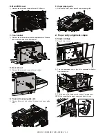
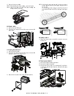
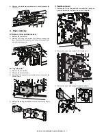
6) Disconnect the connector. Remove the screw, and remove the

paper alignment motor F.

K. Paper alignment motor R

1) Disconnect the connector. Remove the screw, and remove the

paper alignment motor R.

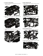
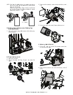
L. Paper alignment plate home position sensor F

1) Remove the screw, remove the mounting plate, and discon-

nect the connector. Remove the paper alignment plate home
position F sensor from the mounting plate.

M. Paper alignment plate home position sensor R

1)

Remove the screw, remove the mounting plate, and discon-
nect the connector. Remove the paper alignment plate home
position R sensor from the mounting plate.

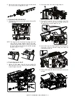
N. Staple tray paper detector

1)

Remove the screw, and remove the sensor holder and the rear
edge regulation plate.

2)

Remove the screw, and remove the jogger F and the jogger R.

3)

Remove the screw, and remove the alignment tray upper unit.

Summary of Contents for MX-FN23

Page 1: ...hed to be used for after sales service only The contents are subject to change without notice 1 PRODUCT OUTLINE 1 1 2 SPECIFICTIONS 2 1 3 EXTERNAL VIEW AND INTERNAL STRUCTURE 3 1 4 ADJUSTMENTS 4 1 5 TROUBLE CODE 5 1 6 OPERATIONAL DESCRIPTIONS 6 1 7 MAINTENANCE 7 1 8 DISASSEMBLY AND ASSEMBLY 8 1 9 SIGNAL LIST 9 1 10 ACTUAL WIRING CHART 10 1 TopPage CONTENTS CODE 00ZMXFN23 S1E MX FN23 MODEL DIGITAL ...

Page 2: ... items 4 1 3 Details of adjustment and setting 4 1 5 TROUBLE CODE 1 Trouble code list 5 1 2 Details 5 1 6 OPERATIONAL DESCRIPTIONS 1 General 6 1 2 Outline of the transport path 6 1 3 Offset mode 6 1 4 Staple mode 6 2 5 Electrical section 6 4 7 MAINTENANCE 1 Maintenance system table 7 1 8 DISASSEMBLY AND ASSEMBLY 1 External view 8 1 2 Paper entry alignment staple 8 2 3 Paper delivery 8 7 4 Others 8...

Page 3: ...by shifting copy by copy and the staple function only one position sta pling Since it is installed to the center tray of the machine there is no extra space for installation The finisher needs a staple cartridge as a consumable part Staple cartridge About 5 000 staples x 3 pcs MX SCX1 Applicable model MX M264U M314U M354U MX M264N M314N M354N Finisher MX FN23 Staple cartridge Digital multifunction...

Page 4: ...city Non staple mode 250 sheets or 35 5mm or less A3 B4 11 x 17 8 5 x 14 8 5 x 13 8K 500 sheets or 71mm or less A4 A4R B5 B5R 8 5 x 11 8 5 x 11R 16K 16KR 8K 16K and 16KR are valid only for China 100 sheets or 35 5mm or less A5 A5R 5 5 x 8 5 5 5 x 8 5R B6R Postcard OHP Label sheet Envelope 20 sheets Note Offset is disabled for Postcard OHP Label Tab paper and Envelope Stapling mode 30 section or 25...

Page 5: ... Yes A4R Yes Yes Yes B5 Yes Yes Yes B5R Yes No Yes A5R Yes 1 No No A5 Yes 1 Yes 1 No B6R Yes 1 No No 8K Yes Yes Yes 16K Yes Yes Yes 16KR Yes No Yes A6R Yes 1 No No Envelope Commercial10 4 1 8 x 9 1 2 Yes 1 No No International DL 110mm x 220mm Yes 1 No No International C5 162mm x 229mm Yes 1 No No Extra Yes 1 No No Custom 7 Yes 1 No No Paper type Thin paper 56 59g m2 Yes 1 Yes 1 Yes 2 Plain paper 6...

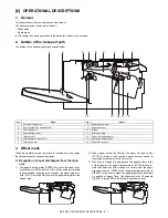
Page 6: ...ection of switch backed paper is discharged to this section and then transported to the switch back section 4 Finisher connection lock pawl This pawl locks the finisher to the machine By turning the separation lever this pawl operates to release lock of finisher 5 Staple cartridge Staples are stored in this cartridge Consumable part 6 Separation lever When replacing a staple cartridge or removing ...

Page 7: ...n during a staple job FPPD1 Paper pass detector Reflection type Detects paper entry in the finisher FPRD Paper rear edge detector Transmission type Detects that the rear edge of paper transported to the compiler reaches the rear edge of the compiler FSTPD Staple tray paper detector Transmission type Detects paper presence in the staple compiler FTPS Delivery tray position sensor Detects the interm...

Page 8: ... Signal name Name Type Function Operation FARLS Alignment roller lift solenoid Electromagnetic solenoid Controls up down movement of the rear edge take up roller FPGS Paper gate solenoid Electromagnetic solenoid Drives the select gate of the paper transport path of paper transported to the switch back section and paper transported to the paper delivery tray FPS Paddle solenoid Electromagnetic sole...

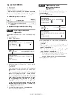
Page 9: ...r completion of the adjustment make staple copies Alignment specification Within 2 5mm ADJ 2 Paper delivery roller descending position adjustment This adjustment is executed when a paper exit jam occurs or when roller marks of the paper delivery roller are attached to paper 1 Execute Sim3 10 2 Select 2 FDRLM ADJUST 3 Enter the set value with 10 key Press C key to clear the entered values Initial v...

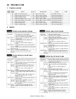
Page 10: ...o confirm that the FDRPS turns ON OFF with SIM3 2 If it does not turn ON OFF check the connection of the connector and the harness of the sensor Replace the sensor Case 3 Cause Motor lock an overcurrent to the motor intrusion of foreign material Check Remedy Select the FDRLM with SIM3 3 to check the operation of the single unit Check to confirm that there is no foreign material in the drive system...

Page 11: ...the connector properly Replace the harness Case 2 Cause Paper alignment plate home position sensor R FAPHPS R trouble Check Remedy Check to confirm that the FAPHPS R turns ON OFF with SIM3 2 If it does not turn ON OFF check the connection of the connector and the harness of the sensor Replace the sensor Case 3 Cause Motor lock an overcurrent to the motor intrusion of foreign material Check Remedy ...

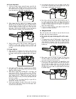
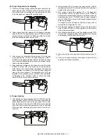
Page 12: ...gate to the finisher side 2 When paper enters the finisher the paper transport motor FPTM is driven at the machine paper delivery speed to receive paper delivery from the machine 3 When the rear edge of paper passes the paper delivery roller of the machine the paper transport motor FPTM is acceler ated to 400mm sec After a lapse of a certain time the paper alignment motor F FPAM F and the paper al...

Page 13: ...he home position The alignment roller lift solenoid FARLS is turned OFF to descend the rear edge take up roller 4 After the paper passes the paper delivery roller the delivery roller lift motor FDRLM is driven upward to lift the paper deliv ery roller to the home position 5 After lifting the paper delivery roller the paddle solenoid FPS is turned OFF to rotate the paper delivery paddler one turn a...

Page 14: ...rm stapling C Paper delivery 1 After stapling the paper alignment motor R FPAM R and the paper alignment motor F FPAM F are driven to separate the paper alignment plate 3mm away from paper At the same time the delivery roller lift motor FDRLM is driven downward by a certain level to shift the paper delivery roller to the paper delivery position discharging the paper bundle from the pro cess tray 2...

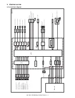
Page 15: ... Output buffer Output buffer Input buffer 3 terminal Reg Input buffer Safety switch On board writing circuit Main unit FPAPD FDRLPD FPDPD FPTPD STLK FCF LD FSL FPAM F FPAM R FDRLM FPDM FPTM FSM FSHPS FSED FSLD FTLM FPGS FPS FARLS FCF FSL 24V 24V 24VR 24VR 5V 24VR 5VR TD62003APG Paper rear edge detector Paper alignment plate home position sensor F Staple tray paper detector Paper level detector Del...

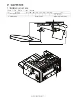
Page 16: ...e 5 Check Clean s Replace U Adjust I Lubricate No Part name 75K 150K 225K 300K 375K 450K 525K 600K Remark 1 Rear edge take up roller 5 5 5 5 5 5 5 5 Replace as needed Supply of service parts 2 Staple cartridge Replace at every 5K Replacement is made by the user 1 2 ...

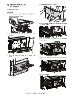
Page 17: ...he finisher 2 Open the front cover Remove the resin clip and remove the front cover 3 Remove the screw and remove the left cabinet of the machine 4 Open the front cabinet of the machine 5 Remove the screw and remove the front cabinet lower and the connection cabinet 6 Release the lock with the separation lever and slide the fin isher to the left 7 Remove the connection plate and slide the finisher...

Page 18: ...e the rear cabinet E Paper entry paper guide unit 1 Remove the screw and remove the paper entry paper guide unit F Upper paper guide 1 Remove the screw and remove the upper paper guide 2 Paper entry alignment staple A Staple cartridge 1 Open the front cover 2 Turn the separation lever to the left to separate the finisher from the machine 3 Pull the lever of the staple case to remove the staple cas...

Page 19: ...ate solenoid mounting plate unit 3 Remove the screw and remove the paper gate solenoid NOTE After fixing the paper gate solenoid the plunger must be in contact with the molt F R of the paper entry lower PG in the free state Press the plunger with your finger to check to confirm that it is in contact with the molt F R of the paper entry upper PG D Safety switch 1 Disconnect the connector remove the...

Page 20: ... the paper rear edge detector and disconnect the con nector G Paper transport motor 1 Disconnect the connector remove the screw and remove the harness holder 2 Disconnect the connector remove the screw and remove the paper transport motor H Rear edge take up roller 1 Remove the E ring the pulley the belt and the parallel pin 2 Disconnect the connector remove the screw and remove the take up soleno...

Page 21: ...n the take up roller and the rear edge regulation plate is 10 12mm J Paper alignment motor F 1 Remove the JAM release knob the one way coupling the Mylar the pulley the SP pin the E ring and the bearing and remove the paper entry roller 2 Remove the screw and remove the upper stay left 3 Remove the E ring and remove the pressure release drive gear Remove the E ring and slide the bearing and remove...

Page 22: ... nect the connector Remove the paper alignment plate home position F sensor from the mounting plate M Paper alignment plate home position sensor R 1 Remove the screw remove the mounting plate and discon nect the connector Remove the paper alignment plate home position R sensor from the mounting plate N Staple tray paper detector 1 Remove the screw and remove the sensor holder and the rear edge reg...

Page 23: ...paper deliv ery roller position sensor B Tray lift motor 1 Remove the front cabinet 2 Remove the harness holder 3 Disconnect the connector remove the screw and remove the lift drive frame 4 Remove the worm gear and the screw and remove the tray lift motor C Paddle solenoid 1 Remove the E ring the paddler drive collar the baring the gear the parallel pin the Mylar the belt and the pulley 2 Remove t...

Page 24: ... position sensor Delivery tray lower limit sensor 1 Remove the delivery tray position sensor and the delivery tray lower limit sensor E Paper delivery motor 1 Remove the compiler 2 Remove the spring the E ring the gear and remove the screw 3 Disconnect the connector remove the paper delivery motor unit 4 Remove the screw and remove the paper delivery motor F Delivery roller lift motor 1 Remove the...

Page 25: ...the tray upper cover 2 Remove the paper delivery extension tray 3 Remove the actuator Remove the paper delivery tray paper detector and disconnect the connector 4 Others A LED PWB 1 Remove the main PWB cover 2 Remove the front cabinet 3 Remove the paper entry paper guide unit 4 Disconnect the connector remove the screw and remove the LED cover Remove the screw and remove the LED PWB B Main PWB 1 R...

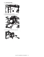
Page 26: ...MBLY AND ASSEMBLY 8 10 5 Fan disassembly 1 Remove one screw from the bottom frame 2 Disconnect the connector of the FAN 3 Remove the FAN together with the mounting plate 4 Remove two screws from the FAN mounting plate ...

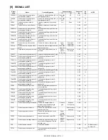
Page 27: ...trol signal phase B Controls the alignment motor F phase B CNF 1 FPAM F B Finisher paper alignment motor F control signal phase B Controls the alignment motor F phase B CNF 3 FPAM R Finisher paper alignment motor R Operates the alignment plate R side CNF 7 12 FPAM RA Finisher paper alignment motor R control signal phase A Controls the alignment motor R phase A CNF 10 FPAM R A Finisher paper alignm...

Page 28: ...osition of the stapler Ready Other than Ready CNC 9 FSM Finisher staple motor Stapling operation of paper bundle CNC 3 6 FSM Finisher staple motor control signal side Controls the staple motor side CNC 3 4 FSM Finisher staple motor control signal side Controls the staple motor side CNC 5 6 FSSW Finisher safety switch Turns OFF the power when the front door is opened to stop the motor CNE 1 2 FSTPD...

Page 29: ...D 5V RxD FIN TxD FIN RES FIN FINDET 5V S GND 24V DSR FIN DTR FIN 5 8 13 9 2 1 12 3 11 4 P GND D SUB 15pin 14 P GND 7 8 3 5 6 4 1 S GND 2 CN C LED LED B26B PHDSS B FSM FSM FSM FSHPS FSM FSLD 9 16 14 12 17 13 15 11 24VR 10 5V FSED FDRLM A FDRLMB FDRLMA FDRLM B 24VR 18 FDRPS 25 21 23 24 22 26 19 FPLD 20 5V S GND 5V S GND FDTPD S GND 5V FSL 2 1 FSL Illumination of the staple unit FSL PHR 2 4 3 1 2 FSM...

Page 30: ...free solder is about 220 C which is about 40 C higher than that of conventional lead solder and its soldering capacity is inferior to conventional one it is apt to keep the soldering iron in contact with the PWB for longer time This may cause land separation or may exceed the heat resistive temperature of components Use enough care to separate the soldering iron from the PWB when completion of sol...

Page 31: ...sfara vid felaktigt batteribyte Använd samma batterityp eller en ekvivalent typ som rekommenderas av apparattillverkaren Kassera använt batteri enligt fabrikantens instruktion German Achtung Explosionsgefahr bei Verwendung inkorrekter Batterien Als Ersatzbatterien dürfen nur Batterien vom gleichen Typ oder vom Hersteller empfohlene Batterien verwendet werden Entsorgung der gebrauchten Batterien nu...

Page 32: ...of Adobe Systems Incorporated Macintosh Mac OS AppleTalk EtherTalk Laser Writer and Safari are registered trademarks or trademarks of Apple Computer Inc IBM PC AT and Power PC are trademarks of International Business Machines Corporation Acrobat Reader Copyright 1987 2002 Adobe Systems Incorporated All rights reserved Adobe the Adobe logo Acrobat and the Acrobat logo are trademarks of Adobe System...

Reviews:

Related manuals for MX-FN23