Sharp MX-4140N Installation Manual Download Page 10

MX-5141FN  MX-4140N/4141N/5140N/5141N (MAIN UNIT)  2 – 6

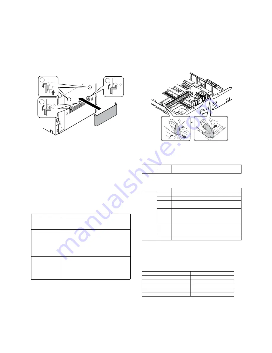
F. Installation of the operation manual pocket

1)

Install the Operation Manual storage (Packed items) cover to
the left side of the machine.

a)

First,  insert  the  pawl  on  the  lower  side  of  the  Operation
Manual pocket.

b)

Then, lift the pawl on the upper side and insert it, and slide
down to install.

* If the FINISHER is installed together with installation of the

machine,  the  Operation  Manual  storage  cover  must  be
installed to the FINISHER.

G. Tray setup

(1)

Simulation setup

Change the tray setting in the "system setting" mode. If "Disabling
of Tray Settings" has been enabled in the system settings (adminis-
trator), the tray settings (except for the bypass tray) cannot be con-
figured.

1)

Enter the SYSTEM SETTING mode.

2)

Touch the [Paper Tray Settings] key.

3)

Touch the [Paper Tray Settings] key to configure the settings.
These  settings  specify  the  paper  type,  paper  size,  and  func-
tions allowed for each paper tray. When the [Tray Settings] key
is  touched,  a  list  appears  showing  the  trays  and  the  current
settings.

4)

Touch the [Change] key in the above screen to change the set-
tings. The following settings can be configured.

(2)

Tray size setup

1)

Pull out the paper tray.

Gently pull the tray out until it stops.

If paper remains in the tray, remove it.

2)

Adjust the guide plates A and B by squeezing their lock levers
and  sliding  them  to  match  the  vertical  and  horizontal  dimen-
sions of the paper to be loaded.

The guide plates A and B are slidable. Slide each guide plate
while squeezing its lock lever.

H. Specifications setup

Used  to  set  the  specifications  with  SIM26  according  to  the  cus-
tomer's request.

To customize the following items after completion of the destination
setup, change the set values.

I.

Image quality check

(1)

Image loss, void area, image off-center check

Make  a  copy  in  the  original  table  mode  and  in  the  RSPF/DSPF
mode. Check to confirm that the image loss and the void area are
in the range shown below.

Item

Description

Type

Select the type of paper that is loaded in the tray. 
The paper types that can be selected vary by paper 
tray.

Size

Select the paper size from the list. The paper sizes 
that can be selected vary by tray. The sizes that 
can be selected may also be restricted by the paper 
type selected above. 
If the desired size does not appear in the list, select 
[Custom Size] and directly enter the size (only for 
the bypass tray).

Feeding Approved 
Job

Select the modes that can be used. If there is a 
function that you do not wish to be used with the 
selected tray, disable the function. When the "Type" 
is other than plain paper, recycled paper, colored 
paper, or a user type, [Fax] and [Internet Fax] 
cannot be selected.

1

1

2

SIM No

Content

26

6

Used to set the destination.

SIM No

Content

26

2

LCC paper size setting

3

Used to set the auditor specification mode.

5

Used to set the count mode of the total counter and 
the maintenance counter.

18

Used to set YES/NO of the toner save mode (Only 
in UK and Japan versions)
* For other destination versions, this setup is 

made by the user program.

52

Used to set YES/NO of counting when non-print 
paper is passed through each counter.

53

Used to set YES/NO of user calibration permission.

65

Used to set the limit number of sheets for stapling.

Content

Standard adjustment value

Lead edge void area

3.0

1.0mm

Rear edge void area

2.0 - 5.0mm

FRONT/REAR void area

2.0

2.0mm

Lead edge image loss adjustment

3.0

1.0mm

Side image loss adjustment

2.0

1.0mm

A

B

Summary of Contents for MX-4140N

Page 1: ...ce these parts with specified ones for maintaining the safety and performance of the set SHARP CORPORATION This document has been published to be used for after sales service only The contents are subject to change without notice MX 4140N 5140N MX 4141N 5141N MODEL DIGITAL FULL COLOR MULTIFUNCTIONAL SYSTEM ...

Page 2: ...e of a step up transformer is also available In this case the capacity must be great enough for the max power consumption of the machine 3 Power frequency waveform The frequency must be within the range of the specified frequency 2 If power waveform is deformed a trouble may occur 4 Safety Be sure to properly ground the machine Grounding earth connection must be performed before inserting the powe...

Page 3: ...ty may be adversely affected and a trouble may be caused There was a trouble in a place where silicon series gas or volatile components are generated Use great care for avoiding this 5 Vibration Avoid installation near a machine which produces vibrations If vibrations are applied to the copier machine copy images may be deflected and a trouble may be caused F Note for handling PWB and electronic p...

Page 4: ...erial on the developing unit Fusing unit Be careful not to leave fingerprints oil grease or other foreign material on the fusing roller and the external heating belt Do not leave the fusing roller in contact state for a long time If these items are neglected a trouble may be generated in the copy and print image quality 2 Transit and delivery A Implements facility and manpower It is recommendable ...

Page 5: ...T 1 Unpacking A Unpacking procedure 1 Remove the PP band 2 Remove the internal packing pads with the machine B Removal of the fixing tape and protection material C Packed items check 1 North America only DSPF model RSPF model No Name Quantity 1 Developer 1 4 2 Operation manual 1 3 Operation manual pocket 1 1 1 2 3 ...

Page 6: ...erial to the position shown in the figure for future use Close the tray which was pulled out 2 Scanner 2 3 mirror unit lock release 1 Remove the optical unit fixing screw and remove the note label B Developing each color installation Be careful not to attach fingerprints or oily dirt on the DV roller sur face 1 Open the front cabinet and remove the waste toner box 2 Check that the lock is released...

Page 7: ...er stir ring toner and developer in the bag supply it to the develop ing unit When replacing developer use an extreme care not to drop developer on the drive section marked with 8 Install the DV cover in the arrow direction A When installing the DV cover be sure to engage the pawl with the boss 9 Secure the DV cover with the two screws 10 Shake the developer unit horizontally a few times When supp...

Page 8: ...ts stores in memory the average sensor detection level as the control level for the ref erence toner density Operating times approx 3 minutes MEMO Be sure to select all of the four colors K C M Y 6 After the machine completes cycling exit the simulation mode by pressing the CA key on the main unit D Installation of individual color toner cartridges The life of each toner cartridge is as follows Bl...

Page 9: ...ositions 3 Insert the cartridge securely until it locks Push it until the click sound is heard E Cleaning of LSU s dust proof glass Dust from the transfer belt or shutter or some other adjacent part may fall onto the LSU during transport or installation Be sure to clean the dust proof glass before checking the image quality 1 Open the front cabinet and remove the waste toner box 2 Detach the LSU c...

Page 10: ...omer s request To customize the following items after completion of the destination setup change the set values I Image quality check 1 Image loss void area image off center check Make a copy in the original table mode and in the RSPF DSPF mode Check to confirm that the image loss and the void area are in the range shown below Item Description Type Select the type of paper that is loaded in the tr...

Page 11: ... is completed EXECUTE key returns to the normal display and the value of the adjustment result is displayed The current skew level for each color is displayed on the SKEW display section No Item SIM 1 Print engine image distortion adjustment Manual adjustment OPC drum phase adjustment Automatic adjustment Color registration adjustment Automatic adjustment 50 22 2 Copy color balance and density che...

Page 12: ...e section and the process sec tion Display Item Content Display Default NOTE MAIN F C Registration adjustment value main scanning direction Cyan laser writing position F side 1 0 199 0 100 M Registration adjustment value main scanning direction Magenta laser writing position F side 1 0 199 0 100 Y Registration adjustment value main scanning direction Yellow laser writing position F side 1 0 199 0 ...

Page 13: ...d paper for color b Note for checking the monochrome copy mode density To check the density use the gray test chart UKOG 0162FCZZ Set the copy density level to Manual 3 in the Text Printed Photo mode Manual In addition all the color balance adjustments in the user adjust ment mode must be set to the default center Check with the gray test chart UKOG 0162FCZZ In the copy density check with the gray...

Page 14: ...istrations one point for the main scanning and one point for the sub scanning are not shifted 3 The resolution of 5 0 5 points can be seen 4 The color difference in gray balance between the F and the R sides is not so great 5 There are no white and black streaks 6 Color texts are clearly reproduced 7 The background density is not so light ...

Page 15: ...nfirm the following 1 There are 12 void areas 2 The resolution of 4 0 5 points can be seen 3 The density difference between the F and the R sides is not so great 4 There are no white and black streaks 5 The background density is not so light 6 The black low density gradation is copied slightly ...

Page 16: ... darker level The density changing direction must not be reversed The density level of each color must be almost at the same level Method 2 When the PCL or the PS printer function is not provided GDI model use this method for check Use SIM 67 25 to print the color balance adjustment sheet and compare each process CMY black patch color balance and the black patch to check the color balance The prin...

Page 17: ...the color balance is registered with SIM63 7 as the service target if the color balance is required to be adjusted select the SERVICE target The copy color balance adjustment is automatically executed and prints the color balance check patch image If there is any streak or unclear print on the printed check pat tern check the print engine for any problems 5 Press EXECUTE key The printer color patc...

Page 18: ...nt step 1 is automatically performed and the color balance check patch image is printed out If there is any streak or unclear print on the printed check pat tern check the print engine for any problems 8 The initial setting menu of the half tone image correction is dis played Press OK key The initial setting of the half tone image correction is per formed 9 Wait until EXECUTE key is displayed When...

Page 19: ...e automatic adjustment and a satisfactory result is not obtained perform the manual color balance adjustment ADJ 10C 2 12 Check the printer color balance and density Refer to the item of the printer color balance and density check When satisfactory color balance and density are not obtained from the automatic adjustment by selecting the factory target in procedure 7 change the factory color balanc...

Reviews: