background image

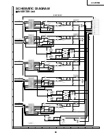
LC-20SH6U

8

7

10

11

12

13

14

15

16

17

18

19

9

6

5

4

3

2

1

A

C

D

E

F

G

H

LC-20SH6U

42

MPWEH

MPWEL

MPOE

MPCE

B0

B1

B2

B3

B4

B5

B6

B7

G0

G1

G2

G3

G4

G5

G6

G7

R0

R1

R2

R3

R4

R5

R6

R7

R7

R6

R5

R4

R3

R2

R1

R0

G7

G6

G5

G4

G3

G2

G1

G0

B7

B6

B5

B4

B3

B2

B1

B0

OFL1

IXB150WJ

20B10U/S5U:DVP-M(A170),20AV6U/SH6U13/15B10U/S5U/AV6U/SH6U:DVP-ML(A150)

1

DVDD3.3

2

PXD24

3

PXD25

4

PXD26

5

PXD27

6

VDIN

7

HDIN/FBIN

8

DVDD3.3

9

DGND

10

VRPD

11

VROD

12

VRMD

13

VIND

14

AVDDD2

15

AVSSD2

16

AVDDD1

17

AVSSD1

18

VRPC

19

VROC

20

VRMC

21

D_PR

22

AVDDC2

23

AVSSC2

24

AVDDC1

25

AVSSC1

26

DVDD

27

DVSS

28

VRPB

29

VROB

30

VRMB

31

AV_SC

32

AVDDB2

33

D_PB

34

AVSSB2

35

AVDB1

36

AVSSB1

37

VRPA

38

VROA

39

VRMA

40

AV_V

41

AVDDA2

42

AV_SY

43

AVSSA2

44

D_Y

45

AVDDA1

46

AVSSA1

47

SVSS

48

DVDD3.3

49

DGND

50

RESET

51

QOECTL

52

PC_H/SDA

53

PC_V/SCL

54

DVDD3.3

55

DGND

56

DVDD1.8

57

MPWEH

58

MOWEL

59

MPOE

60

MPCE

61

MPAH/PCXLK1

62

DVDDSD

63

MDQ15/C656IN7

64

MDQ14/C656IN6

65

MDQ13/C656IN5

66

MDQ12/C656IN4

67

MDQ11/C656IN3

68

DVDD3.3

69

DGND

70

DVDD1.8

71

MDQ10/C656IN2

72

MDQ9/C656IN1

73

MDQ8/C656IN0

74

MDQ7/C656OUT

7

75

MDQ6/C656OUT

6

76

MDQ5/C656OUT5

77

MDQ4/C656OUT4

78

MDQ3/C656OUT3

79

MDQ2/C656OUT

2

80

MDQ1/C656OUT

1

81

DVDDSD

82

DGND

83

MPSEL0

84

XIN

85

XOUT

86

MPSEL1

87

MDQ0/C656OUT0

88

QE/PXCLK0

89

QH

90

QV

91

QDRVHA/QOE

92

DVDD3.3

93

DGND

94

DVDD1.8

95

QDRVHB

96

QDRVHC

97

QDRVHD

98

QDRVHE

99

DVDD3.3

100

DGND

101

DVDDSD

102

QDRVHF

103

QDRVVA

104

QDRVVB

105

QCLKL

106

QRL0

107

DVDD1.8

108

DGND

109

DVDD3.3

110

TEST0

111

LPF1

112

TEST1

113

QRL1

114

QRL2

115

QRL3

116

QRL4

117

DVDD3.3

118

DBND

119

QRL5

120

QRL6

121

QRL7

122

QGL0

123

QGl1

124

DVDD1.8

125

DGND

126

DVDD3.3

127

QGL2

128

QGL3

129

QGL4

130

QGL5

131

QGL6

132

QGL7

133

QBL0

134

QBL1

135

QBL2

136

DVDD1.8

137

DGND

138

DVDD3.3

139

QBL3

140

QBL4

141

QBL5

142

QBL6

143

QBL7

144

QCLKR

145

FRAME_SEL/QBR0

146

QS_ON/QBR1

147

DVDD1.8

148

DGND

149

DVDD3.3

150

QBR2

151

QBR3

152

QBR4

153

QBR5

154

QBR6

155

QBR7

156

DVDD3.3

157

DGND

158

QGR0

159

QGR1

160

L_R

161

U_D

162

DVDD3.3

163

DGND

164

DVDD1.8

165

QGR4

166

QGR5

167

QGR6

168

QGR7

169

QRR0

170

DVDDSD

171

DGND

172

DVDD3.3

173

QRR1

174

QRR2

175

QRR3

176

DVDD1.8

177

DGND

178

DVDD3.3

179

QRR4

180

QRR5

181

QRR6

182

QRR7

183

TSTCLK

184

QBLCA

185

QBLCB

186

QBLCC

187

QBLCD

188

DGND

189

DVDDSD

190

PXCLK

191

PXD00

192

PXD01

193

PXD02

194

PXD03

195

PXD04

196

PXD05

197

DVDD1.8

198

DGND

199

DVDD3.3

200

PXD06

201

PXD07

202

PXD10

203

PXD11

204

PXD12

205

PXD13

206

PXD14

207

DVDDSD

208

PXD15

209

PXD16

210

PXD17

211

PXD20

212

PXD21

213

PXD22

214

PXD23

215

DVDD1.8

216

DGND

C801

33000P

10V

C802

33000P

10V

C803
0.1u

10V

K

C804

0.1u

10V

K

C805
0.1u

10V

K

C806
0.1u

10V

K

C807
0.1u

10V

K

C808
0.1u

10V

K

C809
0.1u

10V

K

C810
0.1u

10V

K

C811
0.1u

10V

K

C812
0.1u

10V

K

C813
33000P

10V

C814
0.1u

10V

K

C815

0.1u

10V

K

C816
0.1u

10V

K

C817
0.1u
B

C818
0.1u

10V

K

C819
0.1u

B

C820
0.1u

10V

K

C821
0.1u

10V

K

C822
0.1u

10V

K

C823

0.1u

10V

K

C825
0.1u

10V

K

C826
0.1u
B

C827
0.1u
B

C828
0.1u

10V

K

C829

33000P

10V

C830

33000P

10V

C831

33000P

10V

C832

0.1u

10V

C833

33000P

10V

C834
33000P

10V

C835
0.1u

10V

C836

33000P

10V

C837

33000P

10V

C838

33000P

10V

C839

33000P

10V

C840

33000P

10V

C841

33000P

10V

C842

33000P

10V

C843

33000P

10V

C844

33000P

10V

C845

33000P

10V

C846

33000P

10V

C847
33000P

10V

C848

33000P

10V

C849

33000P

10V

C850

33000P

10V

C851

0.1u

10V

C852

33000P

10V

C853

33000P

10V

C854

33000P

10V

C855

0.1u

10V

C856

33000P

10V

C857

33000P

10V

C858
0.1u

10V

C859

33000P

10V

C860
10u
10V

KZA176WJ

C861
10u
10V
KZA176WJ

C862

10u

10V

KZA176WJ

C863
0.1u
B

C864

0.1u

B

R801
0

MPCE

DDCRESET

MPWEH

MPWEL

S_Y

OFL1

TCON_OUT_CTL

MPOE

R809

0

R810

100

R811

1M

R819

0

R831

22K

C865

6P

C866

6P

C867

10u

10V

KZA176WJ

C874

0.1u

10V

R839

47

R855

1K

C875

0.01u

C876

1000P

FB803

0006TA

FB806
0006TA

R873

10K

1

2

3

4

5

6

7

8

R874

22K

R868
10K

R867

10K

R869

10K

S_C

TSTCLK

R882

47

R883

47

DVP_H_SYNC

DVP_V_SYNC

FB801

0083GE

SCL1

SDA1

R843

10K

BUS_SELECT_H

R861

22

R860

22

X801

SCA097WJ

54MHz

C887

0.01u

R814
0

R815

0

R832

10K

RS_R7

RS_R6

RS_R5

RS_R4

RS_R3

RS_R2

RS_R1

RS_R0

RS_G7

RS_G6

RS_G5

RS_G4

RS_G3

RS_G2

RS_G1

RS_G0

RS_B7

RS_B6

RS_B5

RS_B4

RS_B3

RS_B2

RS_B1

RS_B0

RS_PCLK

L_R

U_D

R833

47

1

2

3

4

5

6

7

8

9

10

11

12

13

14

15

16

R835

47

1

2

3

4

5

6

7

8

9

10

11

12

13

14

15

16

R837

47

1

2

3

4

5

6

7

8

9

10

11

12

13

14

15

16

COMP_PR

COMP_PB

COMP_Y

*R825

0

*R820

0

*R817

0

R823
1K

DVP33_CTRL

C824
0.1u
B

R826
1K

CVBS

C877
1u
10V

B5V

FB802

0006TA

R812

10K

B3.3V

R803
0

1/8W

R804

47K

Q801
FMMT718

Q802

2SC3928AR

R808

10K

R807
47K

R806

1K
1/10W

R845
820
F

R846

1K

F

PQ200WNA

1

Vin

2

Vc

3

Vo

4

Vadj

5

GND

R847
1.8K

F

C878
10u
10V

KZA176WJ

R824
0

D801

1PS184

1

2

3

R828

27

RS_REV

RS_GSP1

RS_GSP2

R813

22

RS_LS

RS_POWER

RS_GCK

RS_SPIO

R829

22

R816

22

R834

22

R838

22

R848

10

2

1

3

4

FB807

0210TA

C870

1u

10V

C871

47u

6.3V

ASX

PQ018EH1

1

VIN

2

VC

3

VOUT

4

5

GND

OFL2

TO MAIN1(MICON)

DUNTKD673WE

(QPWBXD673WJ)

TO MAIN6(INTERFACE)

TO MAIN5(LVDS)

TO MAIN6(INTERFACE)

*IC801

IC802

IC803

3.3

1.5

1.5

1.5

1.5

3.0

3.0

3.3

0

0

0

0

0

3.3

0

3.3

0

0

0

0

0

3.3

0

3.3

0

3.3

0

0

0

0

0

3.3

0.6

0

3.3

0

1.5

0.7

0.7

1.0

3.3

0

0

0.6

3.3

0

0

3.3

0

3.3

0.5

2.3

2.3

3.3

0

1.5

3.3

2.0

0

3.2

3.3

3.3

3.3

0

1.5

3.3

0

0

1.4

1.5

0

0

3.3

0

3.3

0

1.5

0

0

0

3.3

0

3.3

1.6

0

0

1.6

1.0

1.5

0

3.3

0

1.4

0

1.0

1.0

1.0

1.0

3.3

0

1.0

1.0

1.0

1.0

1.0

1.5

0

3.3

1.0

1.0

1.0

1.0

1.0

1.0

1.0

1.0

1.0

1.5

0

3.3

1.0

1.0

1.0

1.0

1.0

0

0

0

1.5

0

3.3

0

0

0

0

0

0

3.3

0

0

0

3.3

3.3

3.3

0

1.5

0

0

0

0

0

3.3

0

3.3

0

0

0

1.5

0

3.3

0

0

0

0

0

3.2

3.2

3.2

3.2

0

3.3

1.5

1.5

1.5

1.5

1.5

1.5

1.5

1.5

0

3.3

1.5

1.5

1.5

1.5

1.5

1.5

1.5

3.3

1.5

1.5

1.5

1.5

1.5

1.5

1.5

1.5

0

3.2

3.1

0

0

0.1

0.6

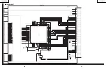
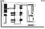
MAIN2 (DVP)

Ë

MAIN Unit-2/7

43

Summary of Contents for LC 20SH6U

Page 1: ...ut notice LCD COLOR TELEVISION CONTENTS IMPORTANT SERVICE SAFETY PRECAUTION 2 SPECIFICATIONS 5 OPERATION MANUAL 6 DIMENSIONS 8 REMOVING OF MAJOR PARTS 9 ADJUSTING PROCEDURE OF EACH SECTION 13 PUBLIC MODE SETTING PROCEDURE 23 TROUBLESHOOTING TABLE 28 MAJOR IC INFORMATIONS 32 BLOCK DIAGRAM 34 OVERALL WIRING DIAGRAM 36 DESCRIPTION OF SCHEMATIC DIAGRAM 38 SCHEMATIC DIAGRAM ËINVERTER Unit 39 ËMAIN Unit...

Page 2: ...teristics as the factory recommended replacement parts shown in this service manual may create shock fire or other hazards WARNING 1 For continued safety no modification of any circuit should be attempted 2 Disconnect AC power before servicing BEFORE RETURNING THE RECEIVER Fire Shock Hazard Before returning the receiver to the user perform the following safety checks 1 Inspect all lead dress to ma...

Page 3: ...REPARATION Ë La réparation ne peut être effectuée que par un technicien spécialisé qui s est parfaitement accoutumé à toute vérification de sécurité et aux conseils suivants AVERTISSEMENT 1 Pour la sécurité continue n entreprendre aucune modification de tout circuit 2 Débrancher l alimentation CA avant la réparation AVANT DE RENDRE LE RECEPTEUR A L UTILISATEUR Incendie et choc électrique Avant de ...

Page 4: ... is higher than the conventional lead solder by 40 C and as it has poor solder wettability you may be apt to keep the soldering bit in contact with the PWB for extended period of time However Since the land may be peeled off or the maximum heat resistance temperature of parts may be exceeded remove the bit from the PWB as soon as you confirm the steady soldering condition Lead free solder contains...

Page 5: ...anel 20 Advanced Super View BLACK TFT LCD Number of dots 921 600 dots VGA Video color systems N358 TV Standard CCIR NTSC TV function TV Tuning System PLL 181 ch STEREO MTS SAP CATV 125 ch Brightness 430 cd m2 Viewing angles H 170 V 170 Audio amplifier 1 0 W 2 Speakers 113 20 41 3 in 42 110 mm 2 pcs INPUT1 COMPONENT IN AUDIO IN INPUT2 VIDEO IN S VIDEO IN AUDIO IN Terminals INPUT3 OUTPUT VIDEO IN AU...

Page 6: ... jack ï Do not set the volume at a high level Hearing experts advise against extended listening at high volume levels Controls Remote sensor SLEEP TIMER indicator The SLEEP TIMER indicator lights up red when the SLEEP TIMER is set to ìONî POWER indicator The POWER indicator lights up green when the power is on and red when in the standby mode the indicator will not light up when the main power is ...

Page 7: ...te Control Use the remote control by pointing it towards the remote sensor window of the main unit Objects between the remote control and sensor window may prevent proper operation Cautions regarding use of the remote control Do not apply shock to the remote control In addition do not expose the remote control to liquids and do not place it in an area with high humidity Do not install or place the...

Page 8: ...LC 20SH6U 8 DIMENSIONS Unit inch mm ...

Page 9: ... the cabinet B fixing screws 9 pcs 4 Remove the cabinet B after opening from the direction of an arrow 5 Disconnect all the connectors from all the PWBs Cabinet B 2 3 1 4 3 Cabinet A Stand Stand Cover 5 5 5 5 5 5 P6705 P5005 P6703 P6702 P6701 P5001 P6700 SC4000 SC5204 SC1701 Main PWB Sub PWB Inverter PWB LED HP PWB PWB HOLDER ...

Page 10: ...crews from the sub PWB and the PWB fixing angle Detach the chassis frame together with its terminals from the sub PWB 9 Remove the inverter PWB fixing screws 3 pcs 10 Remove the LED HP PWB fixing screws 2 pcs 11 Remove the 4 lock screws each from the right and left speakers and take out both the speakers Inverter PWB Main PWB Chassis Frame Sub PWB LED HP PWB 11 10 6 11 7 8 8 9 Speaker R Speaker L ...

Page 11: ... the panel chassis Be careful not to touch the LCD panel s glass faces driver IC PWBs and other components with bare hands Otherwise defects may be caused in the produc tion line 15 Remove the diffusion sheets top lens sheet diffusion sheet bottom and diffusion plate Note Fit the diffusion plate and sheets tightly in the backlight casing If set out of position the panel may get cracked 16 Detach t...

Page 12: ...nnect the service specific extension cable QCNW E540WJQZ between the main PWB SC5203 and the sub PWB P5004 Step Part No Description 2 QCNW E540WJQZ Extension Cable 26 pin Main SC5201 Sub P5002 3 QCNW E540WJQZ Extension Cable 26 pin Main SC5202 Sub P5003 4 QCNW E540WJQZ Extension Cable 26 pin Main SC5203 Sub P5004 Step Part No Description QCNW C458WJQZ Extension Cable 80 pin Main SC1701 LCD CN1 QCN...

Page 13: ...wer For servicing Hold down the INPUT key and VOL key at once and turn on the power switch K appears at the top left of the screen to indicate the inspection process mode Press the CH ù key and VOL key at once The adjustment process mode screen shows up _ To quit turn off the power Or turn off the power switch or turn off the remote controller 3 Key operation in the adjustment process Basic operat...

Page 14: ...the model number is A635A Adjustment Process Menu Page 1 0 1 2 3 4 5 6 7 8 9 10 11 12 13 14 15 16 17 18 19 20 21 22 23 24 25 26 1 M O D E L 3 6 5 A 2 O F A 0 0 F I N C H S I Z E E R R O R N O R E S E T P U B L I C M O D E 0 1 2 3 4 O F F 1 V C H I P E X T V E R R O M 1 0 0 A G A I B U 0 0 0 0 C O N T R O L 5 6 5 5 1 Model by model sending data Separately published 5 2 ROM collection Separately pub...

Page 15: ...0 x 0 271 0 004 0 01 Radius from center point y 0 278 0 004 0 01 Radius from center point White 40 x 0 258 0 002 0 01 Radius from center point y 0 261 0 002 0 01 Radius from center point Adjusting with the bus Cut off RGB CUTOFF2 Fix the G setting at 0 Vary the R and B settings accordingly Adjustment range 40 R 50 B Gain RGB GAIN Reduce the two strong colors Adjustment range 40 R 70 B Reading with...

Page 16: ...G NONE BLOCK NONE TV PG NONE BLOCK NONE TV 14 NONE BLOCK NONE TV MA NONE BLOCK NONE BLOCK CONTENT D BLANK BLOCK BLANK UN BLOCK L BLANK BLOCK BLANK UN BLOCK S BLANK BLOCK BLANK UN BLOCK V BLANK BLOCK BLANK UN BLOCK FV BLANK BLOCK BLANK UN BLOCK CAN ENGLISH RATINGS C NONE BLOCK NONE C8 NONE BLOCK NONE G NONE BLOCK NONE PG NONE BLOCK NONE 14 NONE BLOCK NONE 18 NONE BLOCK NONE CAN FRENCH RATINGS G NON...

Page 17: ...on mentioned above it enters the adjustment process with the power LED red Entering the adjustment process turns off the error detection and turns on TV This enables the operation check to detect errors in the lamp or lamp circuit Check whether ERROR NO RESET on line 4 page 1 of the adjustment process is 1 or more If it is 1 or more it indicates the lamp error detection was executed 8 2 2 Resettin...

Page 18: ...EE THE ADJUSTMENT PROCEDURES R GAIN 0 WHITE BALANCE ADJUSTMENT 2 SEE THE ADJUSTMENT PROCEDURES G GAIN 0 WHITE BALANCE ADJUSTMENT 2 SEE THE ADJUSTMENT PROCEDURES B GAIN 0 WHITE BALANCE ADJUSTMENT 2 SEE THE ADJUSTMENT PROCEDURES RGB GAMMA 1 0 RGB γ COEFFICIENT SETTING NOT USED TABLE OF VARIOUS SETTINGS 9 I2C DATA 0 I2C BUS CONTROL IC DATA WRITE AND READ NOT USED I2C DATA WAIT WRITE AND READ EXECUTED...

Page 19: ...PUT NOT USED OTHER 675 EQUALIZER SETTING WITH OTHER INPUT THAN TV NOT USED BAND5 CNT TV 125 EQUALIZER SETTING WITH TV INPUT NOT USED OTHER 125 EQUALIZER SETTING WITH OTHER INPUT THAN TV NOT USED BAND5 MAX TV 925 EQUALIZER SETTING WITH TV INPUT NOT USED OTHER 925 EQUALIZER SETTING WITH OTHER INPUT THAN TV NOT USED Page No Item Initial Function Response precautions on servicing Value Do not change o...

Page 20: ...SHARP V 100 V PICTURE QUALITY SETTING COMPOSITE S VIDEO NOT USED SECAM AV SHARP H1 150 H PICTURE QUALITY SETTING 1 COMPOSITE S VIDEO NOT USED SECAM AV SHARP H2 150 H PICTURE QUALITY SETTING 2 COMPOSITE S VIDEO NOT USED VIDEO ADJUSTMENT DVP7 PAL60 AV CONT 128 IMAGE SETTING COMPOSITE S VIDEO NOT USED PAL60 AV BRIGHT 128 BRIGHTNESS SETTING COMPOSITE S VIDEO NOT USED PAL60 AV COLOR 37 COLOR DENSITY SE...

Page 21: ...28 TINT SETTING TV NOT USED 525I SHARP V 100 V PICTURE QUALITY SETTING TV NOT USED 525I SHARP H1 100 H PICTURE QUALITY SETTING 1 TV NOT USED 525I SHARP H2 100 H PICTURE QUALITY SETTING 2 TV NOT USED 525P CONT 120 IMAGE SETTING COMPOSITE S VIDEO NOT USED 525P BRIGHT 134 BRIGHTNESS SETTING COMPOSITE S VIDEO NOT USED 525P COLOR 60 COLOR DENSITY SETTING COMPOSITE S VIDEO NOT USED 525P TINT 128 TINT SE...

Page 22: ...C2 162 AVSYNC 1 SYNC JUDGMENT THRESHOLD EXTERNAL INPUT NOT USED COMPSYNC 3 SYNC JUDGMENT THRESHOLD COLOR DIFFERENCE INPUT NOT USED EDS TEST 10 DURATION UNTIL JUDGMENT OF NO EDS TIME DATA SECONDS NOT USED TUNER SETTINGS TUNER2 AFT FARTIME 50 CHANNEL PRESET TIME ADJUSTMENT 1 NOT USED AFT NEARTIME 30 CHANNEL PRESET TIME ADJUSTMENT 2 NOT USED AFT NEARMTIME 10 CHANNEL PRESET TIME ADJUSTMENT 3 NOT USED ...

Page 23: ...e password input screen displayed Procedure The input starts with the leftmost digit Use the numeric keys 1 thru 9 and 10 0 keys on the remote con troller The other keys are not acceptable With a numeric key input will change to The input position will move one digit to the right With all the 3 digits entered the password will be verified 3 The 3 digit password is now verified The password 0 2 7 p...

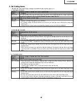
Page 24: ...c mode settings get initialized The adjustment process remains intact 4 Public Mode Menu The guidance is not displayed onscreen Setup procedure To move the cursor up and down use the cursor UP DOWN key remote controller and CH ù Ù key remote controller and set To change the settings use the cursor RIGHT LEFT key remote controller and VOL key remote controller and set To save new settings keep the ...

Page 25: ...tment process the sound volume can be set freely irrespective of this setting In line output sound volume variable the sound volume can be adjusted from 60 to 0 irrespective of pre adjusted value When the sound volume is set higher than the MAX setting by the adjusting process the sound volume control operation is prohibited for turn up and the sound volume should be turned down to MAX in this sta...

Page 26: ...respective of setting Selection Default Explanation Limit in Setting Exception Remarks Selection between Respond and No respond loop provide Respond All the operations by keys except the power key of the unit can be invalidated Inspection mode and hotel menu mode can be started irrespective of setting All the keys can be used in adjustment process inspection mode and hotel menu irrespective of set...

Page 27: ...ws the last memory All the input sources in the model are made selectable When the input output switchable input source is selected and the input source is set to output the setting of input output switching is changed to input at the execution of hotel menu In addition the input output switching by menu is prohibited In TV mode the channel to be set follows the last memory and the content of the ...

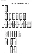
Page 28: ...ge at L state Replace F7701 Accord specified Remove F7701 and check the load side Is there any short circuit in T7702 primary side and periphery Yes Yes Are the outputs of Q5001 in the L state Yes Are the waveform of pins 2 and 4 of T6700 T6704 normal Yes Is the waveform of pin 10 of T6700 T6704 normal Yes Check the error amp circuit D6700 D6701 D6702 D6703 D6704 D6705 Yes Check IC7701 T7702 and i...

Page 29: ...IC3402 as specified Is the output of IC3402 as specified Check the line in question Check IC3402 and its peripheral circuits Check the line in question Check the tuner and its peripheral circuits Check the power line Is the input at pin 1 of IC3402 as specified Is the output of IC3402 as specified Check the line in question Check the line in question Check IC3402 and its peripheral circuits Is the...

Page 30: ...Pin 39 of IC1301 About 8V Pins 65 and 66 of IC1301 About 5V Pins 11 12 and 13 of IC1301 About 3 3V Are the following control signals fed as follows Pin 2 of IC1301 SCL1 Pin 3 of IC1301 SDA1 Check IC1301 and its peripheral circuits Check X1301 and its peripheral circuits Check the line between pin 56 of IC2001 and pin 5 of IC3301 Check the following points 8V Line check IC7004 and its peripheral ci...

Page 31: ... its peripheral circuits Make sure the microprocessor s adjustment process menu settings are as specified No Video Color No S Video Color No Component Color No Color Check the line between pin 8 of SC5202 and pin 31 of IC801 Check the line between pin 3 4 of SC5202 and pin 21 33 of IC801 ...

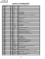
Page 32: ...erial data line 2 for I2C bus 2 system 28 P72 I O SCL2 Serial clock line 2 for I2C bus 2 system EEPROM 29 P71 I O SCL3 N C 30 P70 I O SDA3 N C 31 P67 O TxD TxD at flash write 32 P66 O RxD RxD at flash write 33 P65 O SCLK Clock input at flash write 34 P64 O BUSY Busy output at flash write 35 TxD0 O MPWEL Data signal input for DVP 4 line serial MPWEL 36 RxD0 I MPOE Data output signal for DVP 4 line ...

Page 33: ...elect 69 P23 O OPC_LED OPC LED light up 70 P22 O INV_POW Separately excited inverter power control 71 P21 O VGH Panel power control 72 P20 O POW out DC DC control output 73 P17 I ADP POW Adaptor ON OFF input 74 P16 O HPD_CONTRL N C 75 P15 O ADP_DET_SEL N C 76 P14 O HDMI_SMUTE N C 77 P13 O AD33_CTRL N C 78 P12 O WP_CONT N C 79 P11 O TEMP3 N C 80 P10 O DDC_RESET Video IC reset output Renesas DVP 3D ...

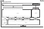
Page 34: ...Y in 40pin C in 31pin OFL SUB_PWB MAIN_PWB LCD_Panel MPWEH MPWEL MPOE MPCE TSTCLK CSYNC Component IN AUDIO IN Y IN Pb IN Pr IN AV IN AUDIO IN VIDEO IN SY IN SC IN S SW U V TUNER VIDEO S IF I2C 3 3V 5V 3V IMZ1A 2 To MAIN MICON AFT VSYNC MPCLK MPRDA MPRCS H OUT V OUT Gradation IC E2PROM VHIBR24L32F 1Y S DETECT SP 2 1 0 1 0W AUDIO_POWER_AMP IC3301 LA4635A Analog SP_MUTE SLEEP S_STBY HP Front Jack 3 5...

Page 35: ...LC 20SH6U 8 7 10 11 12 13 14 15 16 17 18 19 9 6 5 4 3 2 1 A B C D E F G H LC 20SH6U 37 36 OVERALL WIRING DIAGRAM LED HP QCNW E701WJQJ ...

Page 36: ... 8 does not use it CAUTION This circuit diagram is original one therefore there may be a slight difference from yours SAFETY NOTES 1 DISCONNECT THE AC PLUG FROM THE AC OUTLET BEFORE REPLACING PARTS 2 SEMICONDUCTOR HEAT SINKS SHOULD BE REGARDED AS POTENTIAL SHOCK HAZARDS WHEN THE CHASSIS IS OPERATING IMPORTANT SAFETY NOTICE PARTS MARKED WITH å ARE IMPORTANT FOR MAINTAINING THE SAFETY OF THE SET BE ...

Page 37: ...S226 1 2 3 F6701 ZA001WJ AC250V 1A F6700 ZA001WJ AC250V 1A F6702 ZA001WJ AC250V 1A F6703 ZA001WJ AC250V 1A F6704 ZA001WJ AC250V 1A SC6701 Z1338CE TO SUB 1 SIG GND 2 LMP ERR 3 VSH3 3V 4 OFL2 5 OFL1 6 INV GND 7 INV GND 8 INV GND 9 INV GND 10 INV B 11 INV B 12 INV B 13 INV B R6700 1 8K RA 1 4W R6704 1 8K RA 1 4W R6714 1 8K RA 1 4W R6718 1 8K RA 1 4W R6728 1 8K RA 1 4W R6744 560 1 4W R6745 560 1 4W R6...

Page 38: ..._L3 98 VREF 99 A3 3V 100 D_L2 Q2002 KRC104S R2003 22K R2005 22K LUG2001 HA006WJ R2013 100 2 1 3 4 R2054 100 R2053 100 R2050 100 R2036 100 R2030 22K 2 1 3 4 R2024 82K R2047 10K R2068 100 R2070 100 2 1 3 4 Q2019 KRC102S R2043 4 7K Q2020 2SA1037KQ R2039 10K R2059 100K R2066 100 R2063 100 R2002 1K DVP_H_SYNC TCON_OUT_CTL 3 3VA PST3229N 1 2 3 4 5 R2016 47K F R2019 82K F R2020 150K F D2007 RB491D 1 2 3 ...

Page 39: ...K C811 0 1u 10V K C812 0 1u 10V K C813 33000P 10V C814 0 1u 10V K C815 0 1u 10V K C816 0 1u 10V K C817 0 1u B C818 0 1u 10V K C819 0 1u B C820 0 1u 10V K C821 0 1u 10V K C822 0 1u 10V K C823 0 1u 10V K C825 0 1u 10V K C826 0 1u B C827 0 1u B C828 0 1u 10V K C829 33000P 10V C830 33000P 10V C831 33000P 10V C832 0 1u 10V C833 33000P 10V C834 33000P 10V C835 0 1u 10V C836 33000P 10V C837 33000P 10V C8...

Page 40: ... VH0 CS Q1217 KRC104S C1201 10u 25V KZA110WJ C1203 47u 25V ASX Q1218 2SA1530AR R1255 2 7K R1256 2 2K TQ 1 8W 10uH L1201 CNN B3 3V C1270 10u 10V KZA176WJ 3 3V_MICON R1210 68K R1209 100 2 1 3 4 C1277 0 1u 25V Z C1273 0 1u CYF C1272 0 1u 25V C1278 10u 16V KZA109WJ C1271 10u 25V KZA110WJ R1208 1K R1211 1K BUF12800 1 Vdd 2 Vdd 3 REFH 4 Dvdd 5 SCL 6 SDA 7 A0 8 nLD 9 DVss 10 REFL 11 Vss 12 Vss 13 OUT A 1...

Page 41: ...1725 10u 10V KZA176WJ C1706 0 01u C1701 0 01u C1702 0 01u C1703 0 01u C1704 10u 10V KZA176WJ C1705 0 1u SC1701 NA222WJ 1 GND 2 VH63 3 VH55 4 VH47 5 VH39 6 VH31 7 VH23 8 VH15 9 VH7 10 VHO 11 GND 12 VSH 13 VSH 14 VSH 15 GND 16 LBR_S 17 REV 18 LS 19 SPIO 20 SPOI 21 GND 22 GND 23 GND 24 B1 25 B1 26 B2 27 B2 28 B3 29 B3 30 GND 31 CK 32 CK 33 GND 34 GND 35 GND 36 G1 37 G1 38 G2 39 G2 40 G3 41 G3 42 GND ...

Page 42: ...W S _ N O M 6 1 W S W O L S _ C S 3 E N I L _ D 7 1 D N G 8 1 N C 9 1 D N G 0 2 Y B T S _ S 1 2 E T U M _ P S 2 2 2 E T U M _ L 3 2 E T U M _ L 4 2 T U O N I _ S 5 2 T U O N I _ V 6 2 L E S _ V 2 0 2 5 C S J W 6 3 0 A M E C A F R E T N I 6 B U S O T 1 D N G 2 R _ C S N I Y _ P M O C 3 G _ C S N I b P _ P M O C 4 B _ C O N I r P _ P M O C 5 D N G 6 N I S B V C 7 N I _ Y S 8 N I _ C S 9 N I V _ C S ...

Page 43: ... 9 10 11 12 13 14 R713 22K R701 33K FB703 0253TA C749 10u 16V KZA109WJ R758 560K F C743 0 1u 25V Q711 RHP020N06 S D G R757 22K R763 10K R753 33K Q709 UML2N 1 2 3 4 5 C750 10u 25V KZA110WJ R759 20K F C742 0 033u 25V R755 100K D FB706 0253TA R766 510 C748 0 022u 25V Q710 UML1N 1 2 3 5 4 C744 1000P R756 22K IXA828WJ B14V 1 2 3 4 5 6 7 8 9 10 11 12 13 14 C746 33P R764 100 L705 15uH PA154WJ R754 100K D...

Page 44: ...C 8 0 3 1 C u 1 0 V 5 2 Z 4 0 3 1 R 0 0 1 R _ P M O C L E S _ D L _ 3 V A R _ 2 V A 1 0 3 1 R M 1 4 3 3 1 C P 0 0 2 2 2 3 3 1 C u 2 2 0 0 V 5 2 1 0 3 1 D A T 7 6 2 0 X E V 2 1 L _ N O M R _ N O M L _ 2 V A 6 3 3 1 C u 1 0 V 5 2 Z 3 0 3 1 C P 5 0 2 3 1 C u 1 V 0 1 1 L C S 1 0 3 1 X E G 0 5 2 0 B S z H M 2 3 4 8 1 7 0 3 1 C P 6 5 R _ 3 V A 9 2 3 1 C u 1 0 V 5 2 Z 5 3 3 1 C u 2 2 0 0 V 5 2 2 0 3 1 C ...

Page 45: ..._ S T F A C G A E T U M _ L 1 L C S 1 A D S R P _ P M O C Y _ P M O C B P _ P M O C T U O N I _ V T U O N I _ S L E S _ V L E S _ V T S B V C Y _ S C _ S R _ C P L _ C P 4 1 4 3 R 0 5 0 4 3 J J W 2 8 0 A G N E E R G E U L B D E R 1 2 1 r P 3 4 1 b P 5 6 1 Y 4 0 4 3 J J W 2 4 0 A F E T I H W D E R Z Z J W 2 4 0 A F K A J Q 1 R _ P M O C 2 3 L _ P M O C 4 9 0 4 3 R 0 8 1 A R W 8 1 0 8 1 U 6 H S U 6 ...

Page 46: ... 10V KZA030WJ C3313 2 2u 10V KZA030WJ Q3301 DTC314TK Q3302 DTC314TK R3308 12K R3310 3 9K R3311 3 9K C3314 0 015u K C3315 0 015u K Q3304 2SC3928AR R3312 18K R3313 8 2K R3314 10K L_MUTE2 C3317 2 2u 10V KZA030WJ R3306 0 D3301 1PS184 1 2 3 SOUND_GND SP_L SP_R 100u 16V C3301 SYA 10u C3304 SYA 10u C3305 SYA D3302 EX0262TA 7 5V DACM_L DACM_R L_MUTE2 16V C3309 EZA216WJ 1000u 16V C3308 EZA216WJ 1000u 16V C...

Page 47: ...LC 20SH6U 8 7 10 11 12 13 14 15 16 17 18 19 9 6 5 4 3 2 1 A B C D E F G H LC 20SH6U 59 58 ËSUB Unit 3 6 SUB3 AC DC ...

Page 48: ...CC POW B9V B8V C7039 4 7u 16V KZA113WJ R7046 10K R7048 1 8K F C7040 1u 16V PQ200WNA Vref 2 65V 1 VIN 2 VC 3 VO 4 VADJ 5 GND R7001 3 9K F RJ7001 4001GEFW C7043 10u 16V KZA109WJ B8V TO SUB1 TUNER INPUT TO SUB3 AC DC TO SUB6 INTERFACE SUB4 DCDC CONVERTER IC7004 DUNTKD674WE QPWBFD674WJ ËSUB Unit 4 6 ...

Page 49: ...51 6 8K R4052 6 8K R4053 4 7K R4054 4 7K R4056 82K R4055 270K S4051 K0095CE CH 1 2 3 4 S4053 K0095CE CH 1 2 3 4 S4055 K0095CE INPUT 1 2 3 4 S4057 K0095CE POWER 1 2 3 4 S4052 K0095CE MENU 1 2 3 4 S4054 K0095CE VOL 1 2 3 4 S4056 K0095CE VOL 1 2 3 4 KEY2 SIG_VCC KEY1 POW2 QPWBFD674WJ DUNTKD674WE TO SUB3 AC DC TO SUB6 INTERFACE SUB5 CONTROL ËSUB Unit 5 6 ...

Page 50: ...1 W S W O L S _ C S 3 E N I L _ D 7 1 D N G 8 1 N C 9 1 D N G 0 2 Y B T S _ S 1 2 E T U M _ P S 2 2 2 E T U M _ L 3 2 E T U M _ L 4 2 T U O N I _ S 5 2 T U O N I _ V 6 2 L E S _ V 1 A D S 2 0 0 5 P J W 9 8 0 A W E C A F R E T N I 6 N I A M O T A 1 V 5 2 1 1 D N G 2 C C V _ G I S 3 C C V _ G I S 4 C C V _ G I S 5 D N G 6 V 8 1 B 7 V 8 1 B 8 V 3 3 B 9 D N G 0 1 V 5 3 B 1 1 V 5 B 2 1 V 5 B 3 1 U B V ...

Page 51: ...0 0 4 C M R Z Q J W 4 3 0 A U 3 2 1 0 0 0 4 Q S 4 0 1 C R K 3 0 0 4 C u 7 4 V 0 1 J W 9 6 0 A Z K 2 1 0 4 R 0 1 1 0 4 R 0 0 1 0 4 R 0 0 0 0 4 C S Z P J W 3 2 5 A N E C A F R E T N I 6 N I A M O T 1 M E R I 2 A V 3 3 3 D E L _ W O P 4 D N G 5 D E L _ R E M I T _ P E E L S 6 D E L _ C P O 7 C P O 8 V 3 3 B 9 D N G 0 1 R _ P H 1 1 D N G _ P H 2 1 L _ P H 3 1 T E D _ P H 0 0 0 4 J J W 4 1 0 A J K C A ...

Page 52: ...TED WIRING BOARD ASSEMBLIES C4002 C4001 D4006 IC4001 C4000 D4005 C4006 D4007 R4006 C4003 RMC4000 D4002 R4008 R4007 D4003 R4005 R4001 R4000 D4004 D4000 R4003 R4002 R4012 R4004 FB4002 D4001 R4013 FB4001 R4010 FB4003 R4011 J4000 1 LED HP Unit Side A LED HP Unit Chip Parts Side A LED HP Unit Side B ...

Page 53: ...LC 20SH6U 8 7 10 11 12 13 14 15 16 17 18 19 9 6 5 4 3 2 1 A B C D E F G H LC 20SH6U 70 71 MAIN Unit Side A ...

Page 54: ...LC 20SH6U 8 7 10 11 12 13 14 15 16 17 18 19 9 6 5 4 3 2 1 A B C D E F G H LC 20SH6U 72 73 MAIN Unit Chip Parts Side A ...

Page 55: ...LC 20SH6U 8 7 10 11 12 13 14 15 16 17 18 19 9 6 5 4 3 2 1 A B C D E F G H LC 20SH6U 75 74 MAIN Unit Side B ...

Page 56: ...LC 20SH6U 8 7 10 11 12 13 14 15 16 17 18 19 9 6 5 4 3 2 1 A B C D E F G H LC 20SH6U 77 76 MAIN Unit Chip Parts Side B ...

Page 57: ...LC 20SH6U 8 7 10 11 12 13 14 15 16 17 18 19 9 6 5 4 3 2 1 A B C D E F G H LC 20SH6U 79 78 SUB Unit Wiring Side QPWBFD674WJN1 ...

Page 58: ...L3406 C3405 C3423 R3407 R3434 R3402 R3547 R3432 TL3403 TL3412 D3413 D3401 R3410 TL3494 D3402 TL3409 TL3415 D3414 C3499 R3426 R3422 D3410 R3408 R3411 R3539 D3409 C3406 TL3408 TL3419 TL3420 TL3407 R3540 C3501 C3407 D3403 D3404 R3442 R3425 R3428 TL3414 R3443 R3492 R3452 R3435 C3414 Q3407 C3428 R3431 Q3408 Q3409 R3447 R3453 R3449 R3440 D3408 R3459 R3451 R3450 Q3410 R3415 R3465 R3448 R3467 Q3416 R3466 ...

Page 59: ...LC 20SH6U 8 7 10 11 12 13 14 15 16 17 18 19 9 6 5 4 3 2 1 A B C D E F G H LC 20SH6U 83 82 INVERTER Unit Chip Parts Side INVERTER Unit Wiring Side INVERTER Unit Component Side ...

Page 60: ...férence sur la plaquette de circuit imprimé sont rangés dans l ordre alphabétique Ref No Part No Description Code Ref No Part No Description Code PRINTED WIRING BOARD ASSEMBLYS NOT REPLACEMENT ITEM DUNTKD673FMF3 MAIN Unit BX DUNTKD674FMF3 SUB Unit BS DUNTKD675FMF3 INVERTER Unit BG DUNTKD676FMF3 LED HP Unit AR DUNTKD673FMF3 MAIN Unit CAPACITORS C701 VCKYCY1EB333KY J 0 033 25V Ceramic AA C702 VCKYCY...

Page 61: ...CKYCY1EF104ZY J 0 1 25V Ceramic AA C1273 VCKYCY1EF104ZY J 0 1 25V Ceramic AA C1274 RC KZA176WJZZY J 10 10V Ceramic AC C1277 VCKYCY1EF104ZY J 0 1 25V Ceramic AA C1278 RC KZA109WJZZY J 10 16V Ceramic AC C1301 VCEASX0JN107MY J 100 6 3V Electrolytic AC C1302 VCCCCY1HH5R0CY J 50p 50V Ceramic AA C1303 VCCCCY1HH5R0CY J 50p 50V Ceramic AA C1304 VCKYCY1AB105KY J 1 10V Ceramic AB C1305 VCCCCY1HH560JY J 56p ...

Page 62: ...0267TAZZY J Zener Diode 12V AB D1306 RH EX0267TAZZY J Zener Diode 12V AB D1307 RH EX0267TAZZY J Zener Diode 12V AB D2002 VHD1PS184 1Y J Diode AB D2007 VHDRB491D 1Y J Diode AD D5201 RH EX0267TAZZY J Zener Diode 12V AB MISCELLANEOUS PARTS FB703 RBLN 0253TAZZY J Ferrite Bead AA FB704 RBLN 0253TAZZY J Ferrite Bead AA FB705 RBLN 0209TAZZY J Ferrite Bead AB FB706 RBLN 0253TAZZY J Ferrite Bead AA FB707 R...

Page 63: ...817 VRS CY1JF000JY J 0 1 16W Metal Oxide AA R819 VRS CY1JF000JY J 0 1 16W Metal Oxide AA R820 VRS CY1JF000JY J 0 1 16W Metal Oxide AA R823 VRS CY1JF102JY J 1k 1 16W Metal Oxide AA R824 VRS CY1JF000JY J 0 1 16W Metal Oxide AA R825 VRS CY1JF000JY J 0 1 16W Metal Oxide AA R826 VRS CY1JF102JY J 1k 1 16W Metal Oxide AA R828 VRS CY1JF270JY J 27 1 16W Metal Oxide AA R829 VRS CY1JF220JY J 22 1 16W Metal O...

Page 64: ...de AA R2048 VRS CY1JF101JY J 100 1 16W Metal Oxide AA R2050 VRS CY1JF101JY J 100 1 16W Metal Oxide AA R2052 VRS CY1JF101JY J 100 1 16W Metal Oxide AA R2053 VRS CY1JF101JY J 100 1 16W Metal Oxide AA R2054 VRS CY1JF101JY J 100 1 16W Metal Oxide AA R2055 VRS TV2BDR18JY J 0 18 1 10W Metal Oxide AA R2056 VRS CJ1JF101JY J 100 1 16W Metal Oxide AA R2058 VRS CJ1JF472JY J 4 7k 1 16W Metal Oxide AA R2059 VR...

Page 65: ...p 50V Ceramic AA C7734 RC EZA485WJZZ J 1800 25V Electrolytic AF C7735 RC EZA468WJZZ J 2200 16V Electrolytic AE C7736 RC EZA485WJZZ J 1800 25V Electrolytic AF C7737 RC EZA162WJZZ J 0 068 250V Film AD C7739 RC EZA476WJZZ J 350 25V Electrolytic AC C7751 VCKYCY1HB104KY J 0 1 50V Ceramic AA å C7758 RC KZ0104GEZZ J 1500p 250V Ceramic AG å C7759 RC KZ0103GEZZ J 1000p 250V Ceramic AD DUNTKD674FMF3 SUB Uni...

Page 66: ...6W Metal Oxide AA R3412 VRS CY1JF101JY J 100 1 16W Metal Oxide AA R3413 VRS CY1JF104JY J 100k 1 16W Metal Oxide AA R3414 VRS CY1JF000JY J 0 1 16W Metal Oxide AA R3415 VRS CY1JF101JY J 100 1 16W Metal Oxide AA R3416 VRS CY1JF101JY J 100 1 16W Metal Oxide AA R3418 VRS CY1JF471JY J 470 1 16W Metal Oxide AA R3419 VRS CY1JF471JY J 470 1 16W Metal Oxide AA R3420 VRS TQ2BD750JY J 75 1 8W Metal Oxide AA R...

Page 67: ...PRDARA311WJFW Heat Sink AL RJ11 VRS TQ2BD000JY J 0 1 8W Metal Oxide AA RJ12 VRS TQ2BD000JY J 0 1 8W Metal Oxide AA RJ13 VRS TQ2BD000JY J 0 1 8W Metal Oxide AA RJ14 VRS TQ2BD000JY J 0 1 8W Metal Oxide AA RJ15 VRS TQ2BD000JY J 0 1 8W Metal Oxide AA RJ16 VRS TQ2BD000JY J 0 1 8W Metal Oxide AA RJ17 VRS TQ2BD000JY J 0 1 8W Metal Oxide AA RJ18 VRS TQ2BD000JY J 0 1 8W Metal Oxide AA RJ19 VRS TQ2BD000JY J...

Page 68: ...373WJZZ J Coil AC L6702 RCILPA373WJZZ J Coil AC L6703 RCILPA373WJZZ J Coil AC L6704 RCILPA373WJZZ J Coil AC MISCELLANEOUS PARTS P6700 QPLGNA391WJZZ J Plug 2 pin AD P6701 QPLGNA391WJZZ J Plug 2 pin AD P6702 QPLGNA391WJZZ J Plug 2 pin AD P6703 QPLGNA391WJZZ J Plug 2 pin AD P6705 QPLGNA391WJZZ J Plug 2 pin AD TRANSISTORS Q6700 VS2SC5886A 1Y J 2SC5886A AD Q6701 VS2SC5886A 1Y J 2SC5886A AD Q6702 VS2SA1...

Page 69: ...IMER Indicator AD D4002 RH EX0259TAZZY X Zener Diode 12V AB D4003 RH EX0259TAZZY X Zener Diode 12V AB MISCELLANEOUS PARTS J4000 QJAKJA014WJZZ J Headphone Jack AD TRANSISTORS Q4000 VSKRC104S 1Y J KRC104S AA Q4001 VSKRC104S 1Y J KRC104S AA Q4002 VSKRC104S 1Y J KRC104S AA Q4003 VSKRC104S 1Y J KRC104S AA RESISTORS R4000 VRS CY1JF331JY J 330 1 16W Metal Oxide AA R4001 VRS CY1JF182JY J 1 8k 1 16W Metal ...

Page 70: ...TPZA J Bezel AX 4 3 PSLDK2567TPZZ J Diffusion Sheet Top x2 AQ 4 4 POFMA0220TPZZ J Lens Sheet BC 4 5 PSLDK2554TPZZ J Diffusion Sheet Bottom AN 4 6 PSLDK2553TPZZ J Diffusion Plate AX å 4 7 RLMPC2401TPZZ J Lamp Unit x5 AX 4 8 LHLDZ3104TPZA J Backlight Case BA 4 9 PZETE3778TPZZ J Spacer x2 AC 4 10 LX HZ2070TPZS J Screw x4 1 000pcs BR 4 11 LX HZ2055TPZS J Screw x1 1 000pcs BP 5 PSLDMB019WJFW J Back Shi...

Page 71: ...3 3 3 2 3 4 3 2 2 2 6 22 24 24 28 11 10 2 2 5 2 4 2 1 C 30 30 30 30 H F Sub PWB 13 14 15 16 27 12 Main PWB Inverter PWB 1 1 1 1 6 1 5 29 17 LED HP PWB E 20 20 19 19 18 D B D 1 2 1 3 1 3 1 4 1 4 A B A F B 8 5 6 7 4 A A B 4 8 4 9 4 9 4 6 4 5 4 4 4 1 4 2 4 10 4 10 4 3 4 7 4 11 G D C A I D B H G A B E I ...

Page 72: ...J Operation Manual French AF X5 Not Available AAA size Battery x2 S1 SPAKCC532WJZZ Packing Case S2 SPAKPA582WJZZ Wrapping Paper S3 SPAKXB036WJZZ Front Pad S4 SPAKXB037WJZZ Packing AD S5 SSAKA0001SEZZ Polyethylene Bag SERVICE JIGS USE FOR SERVICING QCNW E540WJQZ J Extension Cable 26 pin x3 SC5201 P5002 SC5202 P5003 SC5203 P5004 QCNW D449WJQZ J Extension Cable 13 pin CC P5005 SC6701 QCNW C458WJQZ J ...

Page 73: ...97 LC 20H6U PACKING OF THE SET X3 X5 S2 X2 S4 S4 S3 S1 X1 X4 S5 ...

Page 74: ...ion may be reproduced stored in a retrieval system or transmitted in any form or by any means electronic mechanical photocopying recording or otherwise without prior written permission of the publisher SHARP CORPORATION RC Center NSEC 318 YaoXin Road Economic Technical Development Zone Nanjing China NE0001 S Apr 2006 Printed in China NS Design and Production Information Design NSEC Production NSEC...

Reviews: