LC-20M4U
8
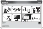
8. Remove the Main PWB fixing screws (4 pcs.).
9. Remove the Inverter PWB fixing screws (3 pcs.).
10. Remove the Jack PWB fixing screw (1 pc.) and Ground fixing screw (1 pc.),
and then remove the Reinforcement plate.
11. Remove the LCD unit fixing screws (2 pcs.).
12. Remove the Switch PWB fixing screws (3 pcs.).
Reinforcement
plate
LCD unit
Main PWB
Jack PWB Ass'y
Switch PWB
Cabinet A
Inverter PWB
12
11
8
9
10
11
P3204
P3203
10
8
Gasket
Summary of Contents for LC 20M4U
Page 5: ...5 LC 20M4U Main unit rear view OPERATION MANUAL Main unit front view Remote Control ...
Page 6: ...LC 20M4U 6 DIMENSIONS Unit inch mm ...
Page 19: ...19 LC 20M4U A B C D E F G H I J 1 2 3 4 5 6 7 8 9 10 JACK Unit INVERTER Unit SWITCH Unit ...
Page 35: ...46 LC 20M4U A B C D E F G H I J 1 2 3 4 5 6 7 8 9 10 MAIN Unit Side A ...
Page 36: ...47 LC 20M4U A B C D E F G H I J 1 2 3 4 5 6 7 8 9 10 MAIN Unit Side B ...
Page 37: ...48 LC 20M4U A B C D E F G H I J 1 2 3 4 5 6 7 8 9 10 JACK Unit Side A JACK Unit Side B ...
Page 38: ...49 LC 20M4U A B C D E F G H I J 1 2 3 4 5 6 7 8 9 10 SWITCH Unit Side B SWITCH Unit Side A ...
Page 51: ...63 LC 20M4U Ref No Part No Description Code Ref No Part No Description Code ...


