background image

03/12/19

XL-HP535E(A)1.fm

7

XL-HP535E

TINSEA042AWZZ

Genera

l Informa

tion


"

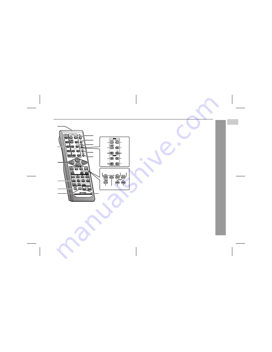
Remote control

Reference page

1. Remote Control Transmitter  . . . . . . . . . . . . . . . . . . . . . . . .  11
2. Disc Number Select Buttons . . . . . . . . . . . . . . . . . . . . . . . .  15
3. Cursor Buttons . . . . . . . . . . . . . . . . . . . . . . . . . . . . . . . . . . .  21
4. Character Input/Disc Direct Search Buttons  . . . . . . . .  17, 22
5. Equaliser Mode Select Button   . . . . . . . . . . . . . . . . . . . . . .  12
6. Extra Bass Button   . . . . . . . . . . . . . . . . . . . . . . . . . . . . . . . .  12
7. On/Stand-by Button  . . . . . . . . . . . . . . . . . . . . . . . . . . . . . . .  12
8. CD Button  . . . . . . . . . . . . . . . . . . . . . . . . . . . . . . . . . . . . . . .  15
9. Tuner (Band) Button   . . . . . . . . . . . . . . . . . . . . . . . . . . . . . .  24

10. Tape Button   . . . . . . . . . . . . . . . . . . . . . . . . . . . . . . . . . . . . .  26
11. Video/Auxiliary Button   . . . . . . . . . . . . . . . . . . . . . . . . . . . .  34
12. Volume Up and Down Buttons  . . . . . . . . . . . . . . . . . . . . . .  12
13. Disc Random Button  . . . . . . . . . . . . . . . . . . . . . . . . . . . . . .  18
14. Disc Clear/Dimmer Button   . . . . . . . . . . . . . . . . . . . . . .  12, 19
15. Disc Stop Button   . . . . . . . . . . . . . . . . . . . . . . . . . . . . . . . . .  16
16. Tape Reverse Play Button . . . . . . . . . . . . . . . . . . . . . . . . . .  26
17. Tape Stop Button  . . . . . . . . . . . . . . . . . . . . . . . . . . . . . . . . .  27
18. Memory/Set Button   . . . . . . . . . . . . . . . .  13, 19, 23, 25, 30, 33
19. Disc Pause Button  . . . . . . . . . . . . . . . . . . . . . . . . . . . . . . . .  16
20. Disc Play or Repeat Button  . . . . . . . . . . . . . . . . . . . . . .  15, 18
21. Tape Forward Play Button   . . . . . . . . . . . . . . . . . . . . . . . . .  26
22. Tape Record Pause Button  . . . . . . . . . . . . . . . . . . . . . .  28, 29
23. MP3 Disc Navigation Mode Select Button  . . . . . . . . . . . . .  21
24. MP3 Disc Display Button . . . . . . . . . . . . . . . . . . . . . . . . . . .  16
25. Enter Button  . . . . . . . . . . . . . . . . . . . . . . . . . . . . . . . . . . . . .  21
26. Clock/Timer Button   . . . . . . . . . . . . . . . . . . . . . . . . .  13, 30, 33
27. Character Button  . . . . . . . . . . . . . . . . . . . . . . . . . . . . . . . . .  22
28. Disc Track Down or Fast Reverse, Tape Fast Wind, 

Tuner Preset Down, Time Down Button   . . . . .  13, 16, 25, 27

29. Disc Track Up or Fast Forward, Tape Fast Wind, 

Tuner Preset Up, Time Up Button   . . . . . . . . . .  13, 16, 25, 27

1

2

10

11

12

8

9

7

4

3

5

6

13

18

19

21

22

14

15

16

17

20

23

26 27 28 29

24 25

1

Summary of Contents for Illustration XL-HP535E

Page 1: ...ide you in operating your SHARP product MICRO COMPONENT SYSTEM XL HP535E Micro Component System consisting of XL HP535E main unit and CP HP535E speaker system Accessories Please confirm that the following accessories are included Remote control 1 AM loop aerial 1 FM aerial 1 XL HP535E A TINSEA042AWZZ 1 MODEL OPERATION MANUAL XL HP535E Note Only the above accessories are included ...

Page 2: ...g of copy right materials and nothing in this OPERATION MANUAL should be implied as giving that authority For other countries Audio visual material may consist of copyrighted works which must not be recorded without the authority of the owner of the copyright Please refer to the relevant laws in your country CAUTION This product is classified as a CLASS 1 LASER product This product contains a low ...

Page 3: ...ult in a fire or other type of acci dent causing damage SHARP will not be held responsible for any damage resulting from use of this unit with a voltage other than that which is specified Volume control The sound level at a given volume setting depends on speaker effi ciency location and various other factors It is advisable to avoid exposure to high volume levels Do not turn the volume on to full...

Page 4: ...utton 15 11 Disc Number Select Buttons 15 12 Disc Direct Play Button 17 13 Illumination Light 12 14 Volume Control 12 15 Disc Track Up or Fast Forward Tape Fast Wind Tuner Preset Up Time Up Button 13 16 25 27 16 Memory Set Button 13 19 23 25 30 33 17 Equaliser Mode Select Button 12 18 Extra Bass Demo Mode Button 10 12 19 Disc Play or Repeat Tape Forward Play Button 15 18 26 20 Disc or Tape Stop Bu...

Page 5: ...or 31 8 Tape Record Indicator 28 9 Daily Timer Indicator 31 10 FM Stereo Mode Indicator 24 11 FM Stereo Receiving Indicator 24 12 Memory Indicator 19 23 13 Tape Reverse Play Indicator 26 14 Tape Forward Play Indicator 26 15 Tape Reverse Mode Indicator 26 16 MP3 Disc Indicator 15 17 Extra Bass Indicator 12 18 Disc Repeat Play Indicator 18 19 Disc Pause Indicator 16 20 Disc Play Indicator 15 4 5 3 2...

Page 6: ...ear panel Reference page 1 Cooling Fan 10 2 Speaker Terminals 9 3 AC Power Lead 10 4 FM 75 Ohms Aerial Socket 9 5 AM Loop Aerial Socket 9 6 Video Auxiliary Audio Signal Input Sockets 34 7 Subwoofer Pre output Socket 35 Speaker system 1 Tweeter 2 Woofer 3 Bass Reflex Duct 4 Speaker Wire 1 3 4 2 1 7 3 2 4 6 5 ...

Page 7: ...Dimmer Button 12 19 15 Disc Stop Button 16 16 Tape Reverse Play Button 26 17 Tape Stop Button 27 18 Memory Set Button 13 19 23 25 30 33 19 Disc Pause Button 16 20 Disc Play or Repeat Button 15 18 21 Tape Forward Play Button 26 22 Tape Record Pause Button 28 29 23 MP3 Disc Navigation Mode Select Button 21 24 MP3 Disc Display Button 16 25 Enter Button 21 26 Clock Timer Button 13 30 33 27 Character B...

Page 8: ...n for Use System connections Left speaker Right speaker Speaker connection see page 9 AM loop aerial FM aerial Aerial connection see page 9 AC power connection see page 10 Wall socket AC 230 240 V 50 Hz Make sure to unplug the AC power lead before any connections ...

Page 9: ...rom the unit for better recep tion Installing the AM loop aerial Speaker connection Connect the black wire to the minus terminal and the red wire to the plus terminal Caution Speaker grilles are removable Assembling Attaching to the wall Wall Screws not supplied Use speakers with an impedance of 6 ohms or more as lower im pedance speakers can damage the unit Do not mistake the right and the left c...

Page 10: ... time Demonstration mode External FM aerial Use an external FM aerial if you require better reception Consult your dealer Cooling fan This product is equipped with a cooling fan inside which begins to run at a specified volume level for better heat radiation Wall socket AC 230 240 V 50 Hz The first time the unit is plugged in the unit will enter the demonstration mode You will see words scroll To ...

Page 11: ...rol and the sensor on the unit with a soft cloth Exposing the sensor on the unit to strong light may interfere with operation Change the lighting or the direction of the unit Keep the remote control away from moisture heat shock and vibrations Test of the remote control Check the remote control after checking all the connections see pages 8 10 Point the remote control directly at the remote sensor...

Page 12: ...ease or decrease the vol ume Bass control X BASS When the power is first turned on the unit will enter the extra bass mode which emphasises the bass frequencies and X BASS will appear To cancel the extra bass mode press the X BASS DEMO X BASS button Equaliser When the EQUALIZER EQUALIZER MODE button is pressed the current mode setting will be displayed To change to a different mode press the EQUAL...

Page 13: ...our or 12 hour display Note The clock can also be set with the remote control 1 Press the ON STAND BY button to turn the power on 2 Press the CLOCK TIMER button 3 Within 10 seconds press the or button to se lect CLOCK and press the MEMORY SET button 4 Press the or button to select 24 hour or 12 hour display and then press the MEMORY SET button 0 00 The 24 hour display will appear 0 00 23 59 AM 12 ...

Page 14: ...al audio source with very little loss in sound quality Notes indicator will light up after the unit reads information on an MP3 disc This system supports MPEG 1 Layer 3 MPEG 2 Layer 3 and VBR files During VBR file playback time counter in the display may differ from its actual playback time Auto power on function When you press any of the following buttons the unit turns on CD button main unit and...

Page 15: ...ith force ER CD20 will appear on the display for 3 seconds and the unit will not function If this occurs press the ON STAND BY button to enter the power stand by mode and then turn the power on again If TV or radio interference occurs during CD operation move the unit away from the TV or radio If a disc is damaged dirty or loaded upside down the disc will skip 1 Press the ON STAND BY button to tur...

Page 16: ...e control Operation Play Press in the stop mode Stop Press in the playback mode Pause Press in the playback mode Press the button to resume play back from the paused point Track up Track down Press in the playback or stop mode If you press the button in the stop mode press the button to start the desired track Fast for ward Fast reverse Press and hold down in the playback mode Release the button t...

Page 17: ... are pressed whilst the disc is stopped press the button to start the desired track on the current disc Notes A track number higher than the number of tracks on the disc can not be selected During random play direct search is not possible 1 Press one of the 1 5 buttons to select the desired disc Selected disc number 2 Within 5 seconds press the CD DIRECT PLAY button on the main unit Use the direct...

Page 18: ...n does not allow you to move to the previous track The beginning of the track being played will be located In random play the unit will select and play tracks automatically You cannot select the order of the tracks Caution After performing repeat or random play be sure to press the CD button Otherwise the disc s will play continuously To repeat all tracks on up to 5 discs Press the button twice To...

Page 19: ...nge the function from CD to another the pro grammed selections will not be cleared During the programme operation random play is not possible During programmed play the CD DIRECT PLAY button will not work 1 Whilst in the stop mode press the MEMORY SET MEMORY button to enter the programming save mode 2 Press one of the 1 5 buttons to select the desired disc Selected disc number 3 Press the direct s...

Page 20: ...n you enter file names on your PC connect words with hyphens This product recognises the first word as title 1 second one as title 2 and third one as title 3 Up to three words can be rec ognised Notes MP3 files must have the extension mp3 Up to 100 folders or 300 files can be read on the unit If either limit is exceeded no more folders files are displayed This unit recognises and displays up to 48...

Page 21: ...he CD button to stop playback NAVI READ appears and the display shows the total number of folders and files on the selected disc 4 Press the MP3 NAVIGATION button 5 Press the or button to se lect FOL T 1 T 2 or T 3 To search files by folder name se lect FOL will flash The following steps describe file search by folder 6 Press the ENTER button The total number of folders or titles appears for 2 sec...

Page 22: ...o go to the next page of character display 6 Press the CHARACTER button and the active character will be entered in the 2nd row of the display To delete an entered character move the cursor to the charac ter with the or button and press the CLEAR DIMMER but ton on the remote control 7 Repeat steps 5 and 6 to enter characters In the folder or title name search you do not have to enter the full name...

Page 23: ...LAY button on the main unit will not work If you press the RANDOM button in the stop mode the MP3 nav igation mode will be cancelled If tracks are programmed using track numbers see Pro grammed play on page 19 In the MP3 navigation mode only programmes by folder or title name are played When you exit the mode the programmes by folder or title name are cleared Even when you exit the MP3 navigation ...

Page 24: ...auto tuning press the TUNING button again To receive an FM stereo transmission Press the TUNER BAND button to display the ST indicator will appear when an FM broadcast is in stereo If the FM reception is weak press the TUNER BAND button to extinguish the ST indicator The reception changes to monau ral and the sound becomes clearer 1 Press the ON STAND BY button to turn the power on 2 Press the TUN...

Page 25: ...ns in memory in order starting with preset channel 1 4 Within 30 seconds press the MEMORY SET MEMORY button to store that station in memory If the MEMORY and preset number indicators go out before the station is memorised repeat the operation from step 2 5 Repeat steps 1 4 to set other stations or to change a pre set station When a new station is stored in memory the station previously memorised w...

Page 26: ... for the best sound Metal or CrO tapes are not rec ommended Do not use C 120 tapes or poor quality tapes as they may cause malfunctions Before loading a tape into the cassette compartment tighten the slack with a pen or a pencil 1 Press the ON STAND BY button to turn the power on 2 Press the TAPE button 3 Open the cassette door by push ing the area marked PUSH EJECT 4 Load a cassette into the cas ...

Page 27: ... playback or stop mode Before recording When recording important selections make a preliminary test to ensure that the desired material is properly recorded SHARP is not liable for damage or loss of your recording arising from malfunction of this unit The volume and sound controls can be adjusted with no effect on the recorded signal Variable Sound Monitor For recording use only normal tapes Do no...

Page 28: ...ast the leader of the tape on which recording cannot be performed 4 Press the button to choose one side or both sides To record on both sides To record on only one side 5 Press the button Recording will be paused 6 Press one of the 1 5 buttons to select the desired disc 7 Within 5 seconds press the CD DIRECT PLAY button to start recording Recording starts from side A Recording is started from the ...

Page 29: ...button Note If you hear a whistling noise whilst recording an AM station move the AM loop aerial Erasing recorded tapes 1 Press the TAPE button 2 Follow steps 2 5 in Recording from the radio 1 Perform steps 1 6 in Recording from a CD or MP3 disc on page 28 2 Within 5 seconds press the button to record on side A or the button for side B 1 Programme discs and tracks see pages 19 23 2 Press the butto...

Page 30: ...or once timer recording works for one time only at a preset time For example if you are away but want to record a programme on a radio station Daily timer Daily timer play or daily timer recording works at the same preset time every day For example set the timer as a wake up call every morning 1 Set the daily timer pages 30 32 2 Set the once timer pages 30 32 Start Daily timer Once timer 1 minute ...

Page 31: ...ress the MEMORY SET button 8 Set the time to finish as in steps 6 and 7 above White Red 9 Switch input with the or button and then press the MEMORY SET button To select the timer playback source CD TUNER or TAPE To select the timer recording source TUNER When you select the tuner select a station by pressing the or button and then press the MEMORY SET button If a station has not been programmed NO...

Page 32: ...g another unit con nected to the VIDEO AUX IN sockets select VIDEO in step 9 This unit will turn on or enter the power stand by mode automatically however the connected unit will not turn on or off 1 Press the CLOCK TIMER button 2 Within 10 seconds press the or button to select ONCE or DAILY and press the MEMORY SET button 3 Within 10 seconds press the or button to select ONCE CALL or DAILY CALL a...

Page 33: ...in 10 seconds press the or button to select SLEEP and press the MEMO RY SET button 4 Press the or button to select the time Maximum 3 hours Minimum 1 minute 3 hours 5 minutes 5 minute intervals 5 minutes 1 minute 1 minute intervals 5 Press the MEMORY SET but ton SLEEP will appear 6 The unit will enter the power stand by mode automatically after the preset time has elapsed The volume will be turned...

Page 34: ...Before plugging in or unplugging the headphones reduce the volume Be sure your headphones have a 3 5 mm 1 8 diameter plug and are between 16 ohms and 50 ohms impedance The recom mended impedance is 32 ohms Plugging in the headphones disconnects the speakers automati cally Adjust the volume using the VOLUME control VCR DVD etc To the line output sockets RCA lead not supplied Red White Red White 1 U...

Page 35: ...t in amplifier Symptom Possible cause The clock is not set to the correct time Did a power failure occur Reset the clock Refer to page 13 When a button is pressed the unit does not respond Set the unit to the power stand by mode and then turn it back on If the unit still malfunctions reset it Refer to page 36 No sound is heard Is the volume level set to 0 Are the headphones connected Are the speak...

Page 36: ... operation will erase all data stored in memory including clock timer settings tuner preset and CD programme Symptom Possible cause Cannot record Is the erase prevention tab re moved Cannot record tracks with proper sound quality Is it a normal tape You cannot record on a metal or CrO tape Cannot erase completely Sound skipping Is there any slack Is the tape stretched Cannot hear treble Are the ca...

Page 37: ...not mark this surface Keep your discs away from direct sunlight heat and excessive moisture Always hold the CDs by the edges Fingerprints dirt or water on the CDs can cause noise or mistracking If a CD is dirty or does not play properly clean it with a soft dry cloth wiping straight out from the centre along the radius Maintenance Cleaning the tape handling parts Dirty heads capstans or pinch roll...

Page 38: ... W 10 T H D RMS 150 W 75 W 75 W 10 T H D Output terminals Speakers 6 ohms Headphones 16 50 ohms recommended 32 ohms Subwoofer pre output audio signal 200 mV 10 k ohms at 70 Hz Input terminals Video Auxiliary audio signal 500 mV 47 k ohms Type 5 disc multi play compact disc player Signal readout Non contact 3 beam semiconductor laser pickup D A converter 1 bit D A converter Frequency response 20 20...

Page 39: ...osts if the product has to be returned for repair This warranty does not extend to accessories defects or injuries caused by or resulting from causes not attributable to faulty parts or the manufacture of the product including but not limited to defect or injury caused by or resulting from misuse abuse neglect accidental damage improper voltage liquid spillage vermin infestation software or any al...

Page 40: ...WITHIN AUSTRALIA REGARDING YOUR LOCAL SHARP APPROVED SERVICE CENTRE VISIT OUR WEBSITE AT www sharp net au OR CALL SHARP LOCAL CALL 1 300 135 022 SHARP CORPORATION OF AUSTRALIA PTY LIMITED A B N 40 003 039 405 1 Huntingwood Drive Blacktown NSW 2148 FOR PRODUCTS PURCHASED IN NEW ZEALAND CONTACT YOUR SELLING DEALER RETAILER OR CALL SHARP CUSTOMER SERVICES TELEPHONE 09 573 0111 FACSIMILE 09 573 0113 W...

Reviews: